Page 9 of 27

Battery Information
The Altima Hybrid utilizes two batteries in order to supply both high and low voltage.
Low Voltage Battery
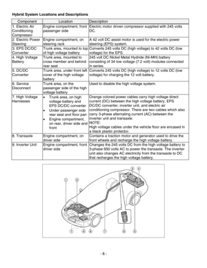
The Altima Hybrid contains a lead-acid 12 volt DC low voltage battery.
The low voltage battery is located in the passenger rear quarter panel
well of the trunk and is concealed by a trim cover. The negative (-) 12
volt battery cable can be accessed through an access panel in the
trim cover.
The 12 volt battery powers the vehicle’s 12 volt electrical system,
similar to a conventional vehicle. As with conventional vehicles, the 12
volt battery is grounded to the metal chassis of the vehicle. However,
the 12 volt battery is charged by the high voltage battery through the
DC/DC converter.
High Voltage Battery
- 9 -
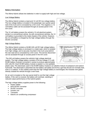
The Altima Hybrid contains a Ni-MH 245 volt DC high voltage battery.
The high voltage battery is enclosed in a metal case, which is isolated
from high voltage, and is securely mounted in the trunk area behind
the rear seat and is concealed by a trim cover. The service disconnect
can be accessed through an access panel in the trim cover.
The 245 volt battery powers the vehicle’s high voltage electrical
system. The high voltage battery consists of 34 low voltage (7.2 volt)
Ni-MH battery modules connected in series to produce approximately
245 volts DC. Each Ni-MH battery module is sealed in a non-spillable
plastic case. The electrolyte used in the Ni-MH battery module is an alkaline mixture of potassium and sodium
hydroxide. The electrolyte is absorbed into the battery ce ll plates and forms a gel that should not normally leak,
even in a collision. In the unlikely event that the high voltage battery is overcharged, the modules vent gases
directly outside the vehicle through a vent hose.
An air vent is located on the rear parcel shelf to cool the high voltage
battery. If the vent is covered, the battery will overheat, resulting in
reduced output performance of the hybrid system.
The high voltage battery supplies power to the following:
• Power cables
• EPS DC/DC converter
• DC/DC converter
• Inverter unit
• Transaxle
• Electric air conditioning compressor
Page 10 of 27
- 10 -
High Voltage Battery Specifications
High Voltage Battery Specifications
High voltage battery voltage 245 V
Number of Ni-MH battery modules in the pack34
Ni-MH battery module voltage 7.2 V
Ni-MH battery module dimensions 5 x 1 x 11 in. (125.5 x 25.1 x 276.1 mm)
Ni-MH module weight 2.2 lbs (1.0 kg)
Ni-MH high voltage battery dimensions 8 x 34 x 19 in. (200.8 x 853.4 x 476.9 mm)
Ni-MH high voltage battery weight 114.6 lbs (52 kg)
High Voltage Battery Recycling
The high voltage battery is recyclable. For information regarding recycling of the high voltage battery, contact
the nearest Nissan dealer or Nissan customer assist ance at: United States: 1-800-NISSAN-1 (1-800-647-7261)
or in Canada: 1-800-387-0122.
Page 11 of 27
High Voltage Safety
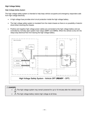
High Voltage Safety System
The high voltage safety system is intended to help keep vehicle occupants and emergency responders safe
from high voltage electricity.
• A high voltage fuse provides short circuit protection inside the high voltage battery.
• The high voltage safety system is insulated from the metal chassis so there is no possibility of electric
shock when touching the chassis.
• Positive and negative high voltage power cables are connected to the high voltage battery and are
controlled by normally open system main relays (SMR1 and SMR2). When the vehicle is shut off, the
relays stop electrical flow from leaving the high voltage battery.
DANGER:
•
The high voltage system may remain powered for up to 10 minutes after the vehicle is shut
off.
•
The high voltage battery retains high voltage at all times.
- 11 -
Page 12 of 27
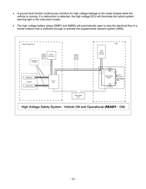
• A ground fault monitor continuously monitors for high voltage leakage to the metal chassis while the
vehicle is running. If a malfunction is detected, the high voltage ECU will illuminate the hybrid system
warning light in the instrument cluster.
• The high voltage battery relays (SMR1 and SMR2) will automatically open to stop the electrical flow in a
frontal collision that is sufficient enough to activate the supplemental restraint system (SRS).
- 12 -
Page 13 of 27
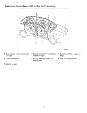
Supplemental Restraint System (SRS) and Seat Belt Pre-tensioners
1. Supplemental curtain side-impact air bags 2. Supplemental seat-mounted side-
impact air bags 3. Supplemental front-impact air
bags
4. Crash zone sensor 5. Air bag diagnosis sensor unit
(control unit) 6. Seat belt pre-tensioners
7. Satellite sensors
- 13 -
Page 14 of 27

Emergency Response
On arrival, first responders should follow their standard operating procedures for vehicle incidents.
Emergencies involving the Altima Hybrid may be handled like other automobiles, except as noted in these
guidelines for Extrication, Fire, Recovery, Spills, First Aid, and Submersion.
DANGER:
•
Failure to disable the high voltage electrical system before emergency response procedures are
performed may result in serious injury or death from electrical shock.
• Failure to disable the low and high voltage electrical systems before emergency response
procedures are performed may result in serious injury or death from the unintentional deployment of
the SRS.
WARNING:
• Never assume that the Altima Hybrid is shut off simply because it is quiet.
• Always observe the instrument cluster for the READY operation indicator light (green) status to
verify whether the vehicle is on or shut off. The vehicle is shut off when the READY operation
indicator light (green) is off.
• The use of personal protective equipment (PPE) su ch as insulated rubber gloves, insulated rubber
boots, and insulated rubber mats must be used when disabling the high voltage electrical system.
- 14 -
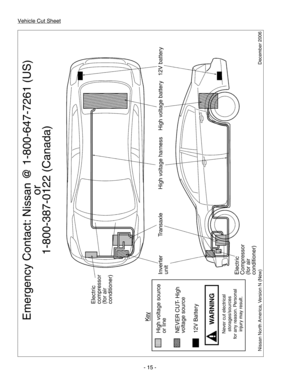
Page 15 of 27
Page 16 of 27

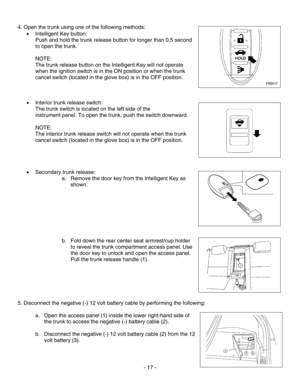
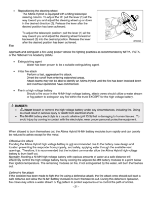
NOTE:
Repositioning the power seats, operating the power door locks and operating the power trunk release must be
done prior to 12 volt battery disconnection.
Automatic Door Locks (Not Applicable to 2007 or 2008 Model Years)
This vehicle is equipped with an automatic door lock system. All door
locks will unlock automatically when the ignition switch is placed in the
OFF position or when the power door lock switch (located on the front LH
or RH door trim panel) is manually operated as shown.
Extrication
1. Immobilize the vehicle
a. Move the shift lever to the P (Park) position.
b. Shut the vehicle OFF by pressing the push-button ignition
switch.
c. Chock the wheels.
d. Set the parking brake.
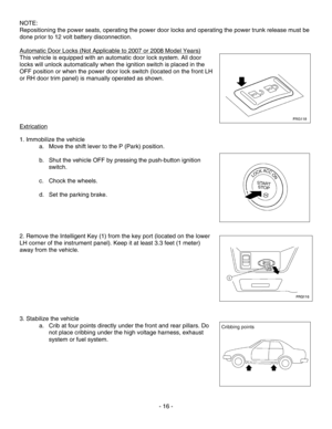
2. Remove the Intelligent Key (1) from the key port (located on the lower
LH corner of the instrument panel). Keep it at least 3.3 feet (1 meter)
away from the vehicle.
3. Stabilize the vehicle a. Crib at four points directly under the front and rear pillars. Do
not place cribbing under the high voltage harness, exhaust
system or fuel system.
- 16 -


 and Seat Belt Pre-tensioners
1. Supplemental curtain side-impact air bags 2. Supplemental seat-mounted side-
impact air bags 3. Supplemental front-impact a")
