Page 17 of 23
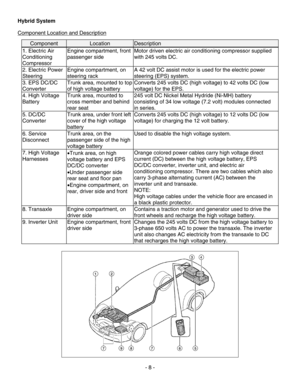
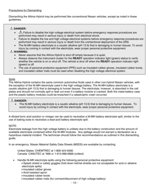
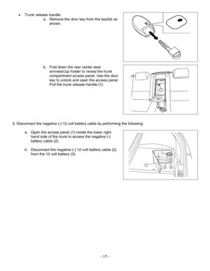
• Trunk release handle:
a. Remove the door key from the keyfob as
shown.
b. Fold down the rear center seat
armrest/cup holder to reveal the trunk
compartment access panel. Use the door
key to unlock and open the access panel.
Pull the trunk release handle (1).
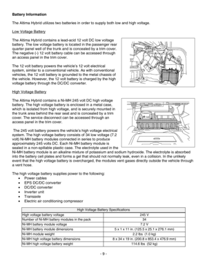
3. Disconnect the negative (-) 12 volt battery cable by performing the following:
a. Open the access panel (1) inside the lower right-
hand side of the trunk to access the negative (-)
battery cable (2).
b. Disconnect the negative (-) 12 volt battery cable (2)
from the 12 volt battery (3).
- 17 -
Page 18 of 23
 on the service disconnect ha")
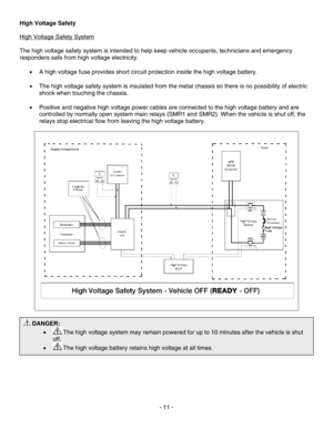
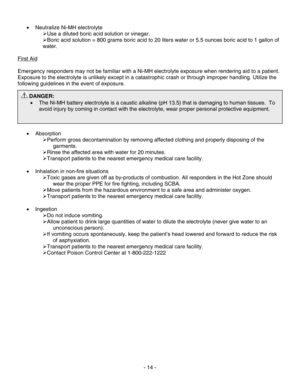
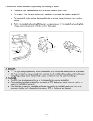
4. Remove the service disconnect by performing the following as shown:
a. Open the access panel inside the trunk to access the service disconnect.
b. Pull upward (1) on the service disconnect handle and then rotate the handle downward (2).
c. Pull outward (3) on the service disconnect handle to remove the service disconnect from the
battery.
d. Wait 3 minutes before handling SRS system components and 10 minutes before handling high
voltage system components while the system discharges
DANGER:
•
The high voltage system may remain powered for up to 10 minutes after the vehicle is disabled.
•
To prevent serious injury or death from electrical shock avoid touching, cutting, or breaching any
orange high voltage power cable or high voltage component while the system discharges.
WARNING:
• The SRS may remain powered for up to 3 minutes after the vehicle is disabled.
• To prevent serious injury or death from unintentional SRS deployment, avoid crushing, cutting, or
breaching the SRS components.
• If the disabling procedures cannot be performed completely, proceed with caution as there is no
assurance that the high voltage electrical system, SRS, or fuel pump are disabled.
- 18 -
Page 19 of 23

Alternative High Voltage System Shut Down Procedure
NOTE:
If the service disconnect procedure cannot be performed, the following alternative shut down procedure is
acceptable.
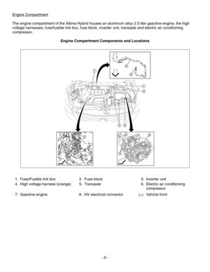
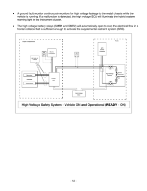
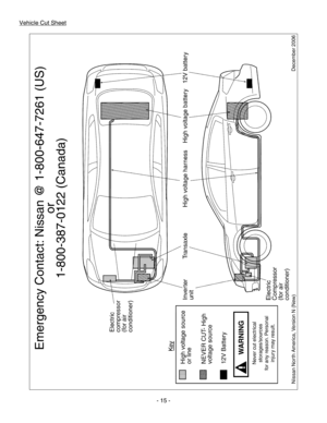
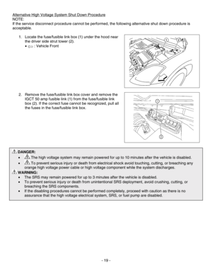
1. Locate the fuse/fusible link box (1) under the hood near
the driver side strut tower (2).
• : Vehicle Front
- 19 -
DANGER:
•
The high voltage system may remain powered for up to 10 minutes after the vehicle is disabled.
•
To prevent serious injury or death from electrical shock avoid touching, cutting, or breaching any
orange high voltage power cable or high voltage component while the system discharges.
WARNING:
• The SRS may remain powered for up to 3 minutes after the vehicle is disabled.
• To prevent serious injury or death from unintentional SRS deployment, avoid crushing, cutting, or
breaching the SRS components.
• If the disabling procedures cannot be performed completely, proceed with caution as there is no
assurance that the high voltage electrical system, SRS, or fuel pump are disabled.
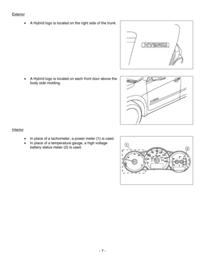
2. Remove the fuse/fusible link box cover and remove the
IGCT 50 amp fusible link (1) from the fuse/fusible link
box (2). If the correct fuse cannot be recognized, pull all
the fuses in the fuse/fusible link box.
Page 20 of 23
 at the front bottom of the seat
cushion forward (one for each side), and pull the s")
Removal of HV Battery
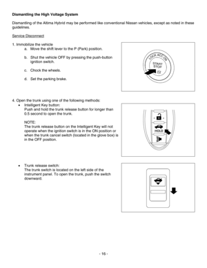
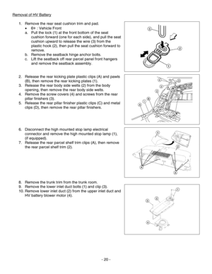
1. Remove the rear seat cushion trim and pad.
• : Vehicle Front
a. Pull the lock (1) at the front bottom of the seat
cushion forward (one for each side), and pull the seat
cushion upward to release the wire (3) from the
plastic hook (2), then pull the seat cushion forward to
remove.
b. Remove the seatback hinge anchor bolts.
c. Lift the seatback off rear parcel panel front hangers
and remove the seatback assembly.
2. Release the rear kicking plate plastic clips (A) and pawls
(B), then remove the rear kicking plates (1).
3. Release the rear body side welts (2) from the body
opening, then remove the rear body side welts.
4. Remove the screw covers (4) and screws from the rear
pillar finishers (3).
5. Release the rear pillar finisher plastic clips (C) and metal
clips (D), then remove the rear pillar finishers.
6. Disconnect the high mounted stop lamp electrical
connector and remove the high mounted stop lamp (1),
(if equipped).
7. Release the rear parcel shelf trim clips (A), then remove
the rear parcel shelf trim (2).
8. Remove the trunk trim from the trunk room.
9. Remove the lower inlet duct bolts (1) and clip (3).
10. Remove lower inlet duct (2) from the upper inlet duct and
HV battery blower motor (4).
- 20 -
Page 21 of 23
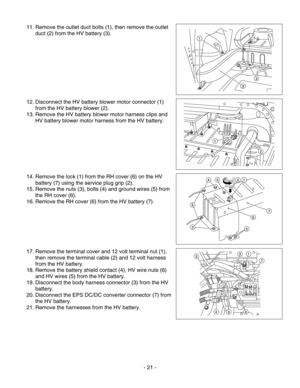
11. Remove the outlet duct bolts (1), then remove the outlet
duct (2) from the HV battery (3).
12. Disconnect the HV battery blower motor connector (1)
from the HV battery blower (2).
13. Remove the HV battery blower motor harness clips and
HV battery blower motor harness from the HV battery.
14. Remove the lock (1) from the RH cover (6) on the HV
battery (7) using the service plug grip (2).
15. Remove the nuts (3), bolts (4) and ground wires (5) from
the RH cover (6).
16. Remove the RH cover (6) from the HV battery (7).
17. Remove the terminal cover and 12 volt terminal nut (1),
then remove the terminal cable (2) and 12 volt harness
from the HV battery.
18. Remove the battery shield contact (4), HV wire nuts (6)
and HV wires (5) from the HV battery.
- 21 - rom
19.
Disconnect the body harness connector (3) from the HV
battery.
20. Disconnect the EPS DC/DC converter connector (7) f
the HV battery.
21. Remove the harnesses from the HV battery.
Page 22 of 23
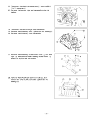
22. Disconnect the electrical connectors (1) from the EPS
DC/DC converter (2).
23. Remove the harness clips and harness from the HV
battery.
24. Disconnect the vent hose (3) from the vehicle.
25. Remove the HV battery bolts (1) from the HV battery (2).
26. Remove the HV battery from the vehicle.
27. Remove the HV battery blower motor bolts (1) and duct
clips (2), then remove the HV battery blower motor (3)
and ducts (4) from the HV battery.
28. Remove the EPS DC/DC converter nuts (1), then
remove the EPS DC/DC converter (2) from the HV
battery (3).
- 22 -
Page 23 of 23
- 23 -
Removal of HV Components
Dismantling the remainder of the Nissan Altima Hybrid may be performed l\
ike conventional Nissan vehicles
once the HV system is disabled.
Page:
< prev 1-8 9-16 17-24


, then remove the outlet
duct (2) from the HV battery (3).
12. Disconnect the HV battery blower motor connector (1)
from the HV battery blow")
 from the EPS
DC/DC converter (2).
23. Remove the harness clips and harness from the HV
battery.
24. Disconnect the vent hose (3) from")
