2010 NISSAN 370Z COUPE battery replacement
[x] Cancel search: battery replacementPage 79 of 409
Black plate (77,1)
Model "Z34-D" EDITED: 2009/ 9/ 10
If this indicator appears, push the push-button
ignition switch while lightly turning the steering
wheel right and left.3. Key insertion indicatorThis indicator appears when the key needs to be
inserted into the key port. (For example, the
Intelligent Key battery is discharged.)
If this indicator appears, insert the key into the
key port in the correct direction. (See “PUSH-
BUTTON IGNITION SWITCH” in the “5. Start-
ing and driving” section.)4. Intelligent Key removal indicatorThis indicator appears when the driver’s door is
opened with the ignition switch in the OFF or
LOCK position and the Intelligent Key placed in
the key port. A key reminder chime also sounds.
If this indicator appears, remove the Intelligent
Key from the key port and take it with you when
leaving the vehicle.5. NO KEY warningThis warning appears in either of the following
conditions.
No Intelligent Key inside the vehicle:
The warning appears when the door is closed
with the Intelligent Key left outside the vehicle
and the ignition switch in the ACC or ON
position. Make sure that the Intelligent Key isinside the vehicle.
Unregistered Intelligent Key:
The warning appears when the ignition switch is
pushed from the LOCK position and the
Intelligent Key cannot be recognized by the
system. You cannot start the engine with an
unregistered key. Use the registered Intelligent
Key.
See “INTELLIGENT KEY SYSTEM” in the “3.
Pre-driving checks and adjustments” section for
more details.
6. SHIFT “P” warning (Automatic Trans-
mission models)This warning appears when the ignition switch is
pushed to stop the engine with the selector lever
in any position except the P (Park) position.
If this warning appears, move the selector lever
to the P (Park) position or push the ignition
switch to the ON position.
An inside warning chime will also sound. (See
“INTELLIGENT KEY SYSTEM” in the “3. Pre-
driving checks and adjustments” section.)7. “PUSH” warning (Automatic Trans-
mission models)This warning appears when the selector lever is
moved to the P (Park) position with the ignition
switch in the ACC position after the SHIFT “P”
warning appears.
To push the ignition switch to the OFF position,
perform the following procedure:
SHIFT “P” warning
?(Move the selector
lever to “P”) ?PUSH warning ?(Push the
ignition switch ?ignition switch position is
turned to ON) ?PUSH warning ?(Push the
ignition switch ?ignition switch position is
turned to OFF)
8. Intelligent Key battery discharge in-
dicatorThis indicator appears when the Intelligent Key
battery is running out of power.
If this indicator appears, replace the battery with
a new one. (See “INTELLIGENT KEY BATTERY
REPLACEMENT” in the “8. Maintenance and
do-it-yourself” section.)9. Engine start operation indicator
(Manual Transmission models)This indicator means that the engine will start by
pushing the ignition switch with the clutch pedal
depressed.
Instruments and controls
2-17
Page 119 of 409

Black plate (119,1)
Model "Z34-D" EDITED: 2009/ 9/ 10
computer.
. When the vehicle is parked near a parking
meter.
In such cases, correct the operating conditions
before using the Intelligent Key function or use
the mechanical key.
Although the life of the battery varies depending
on the operating conditions, the battery’s life is
approximately 2 years. If the battery is dis-
charged, replace it with a new one.
When the Intelligent Key battery is almost
discharged, insert the Intelligent Key into the
Intelligent Key port to start the engine. Replace
the discharged battery with a new one as soon
as possible. For more details, see “PUSH-
BUTTON IGNITION SWITCH” in the “5. Start-
ing and driving” section.
Since the Intelligent Key is continuously receiv-
ing radio waves, if the key is left near equipment
which transmits strong radio waves, such as
signals from a TV and personal computer, the
battery life may become shorter.
For information regarding replacement of a
battery, see “INTELLIGENT KEY BATTERY
REPLACEMENT” in the “8. Maintenance and
do-it-yourself” section.
Because the steering wheel is locked electri-
cally, unlocking the steering wheel with the ignition switch in the LOCK position is impos-
sible when the vehicle battery is completely
discharged. Pay special attention that the
vehicle battery is not completely discharged.
As many as 4 Intelligent Keys can be registered
and used with one vehicle. For information about
the purchase and use of additional Intelligent
Keys, contact a NISSAN dealer.
CAUTION
.
Do not allow the Intelligent Key,
which contains electrical compo-
nents, to come into contact with
water or salt water. This could affect
the system function.
. Do not drop the Intelligent Key.
. Do not strike the Intelligent Key
sharply against another object.
. Do not change or modify the Intel-
ligent Key.
. Wetting may damage the Intelligent
Key. If the Intelligent Key gets wet,
immediately wipe until it is comple-
tely dry.
. Do not place the Intelligent Key for
an extended period in an area where
temperatures exceed 140 8F (60 8C) . .
Do not attach the Intelligent Key
with a key holder that contains a
magnet.
. Do not place the Intelligent Key near
equipment that produces a mag-
netic field, such as a TV, audio
equipment, personal computer or
cellular phone.
If an Intelligent Key is lost or stolen, NISSAN
recommends erasing the ID code of that
Intelligent Key from the vehicle. This may prevent
the unauthorized use of the Intelligent Key to
operate the vehicle. For information regarding
the erasing procedure, contact a NISSAN deal-
er.
The Intelligent Key function can be disabled. For
information about disabling the Intelligent Key
function, contact a NISSAN dealer.
Pre-driving checks and adjustments
3-7
Page 284 of 409
Black plate (284,1)
Model "Z34-D" EDITED: 2009/ 9/ 10
SSD0826
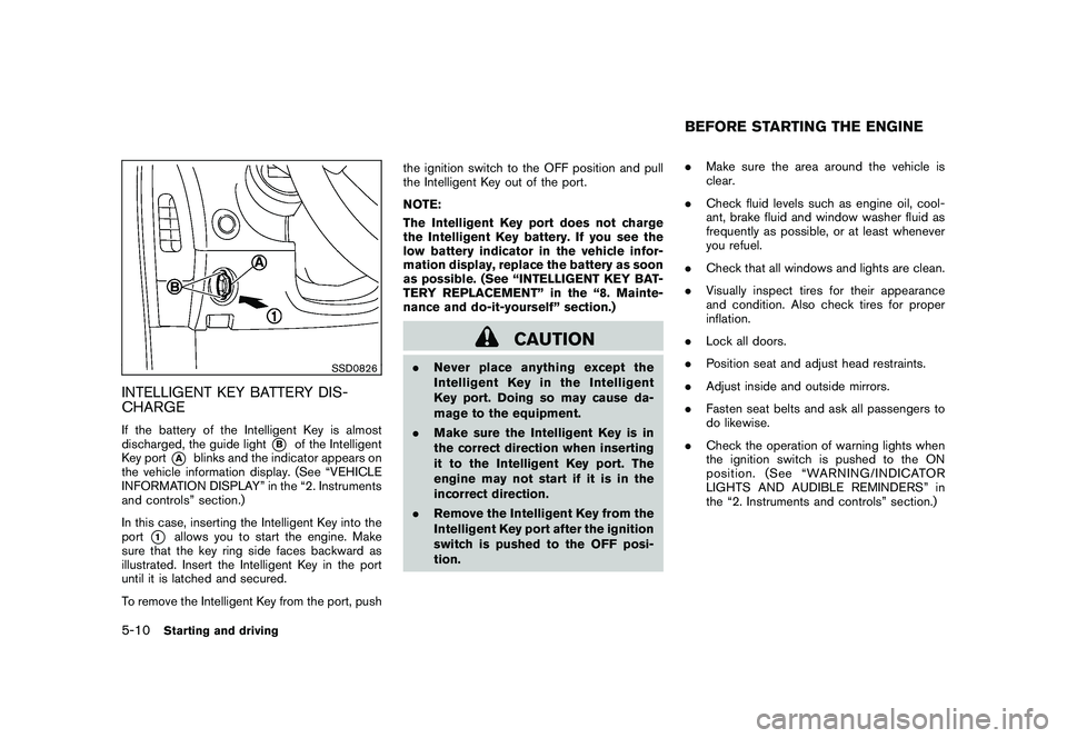
INTELLIGENT KEY BATTERY DIS-
CHARGEIf the battery of the Intelligent Key is almost
discharged, the guide light
*B
of the Intelligent
Key port
*A
blinks and the indicator appears on
the vehicle information display. (See “VEHICLE
INFORMATION DISPLAY” in the “2. Instruments
and controls” section.)
In this case, inserting the Intelligent Key into the
port
*1
allows you to start the engine. Make
sure that the key ring side faces backward as
illustrated. Insert the Intelligent Key in the port
until it is latched and secured.
To remove the Intelligent Key from the port, push the ignition switch to the OFF position and pull
the Intelligent Key out of the port.
NOTE:
The Intelligent Key port does not charge
the Intelligent Key battery. If you see the
low battery indicator in the vehicle infor-
mation display, replace the battery as soon
as possible. (See “INTELLIGENT KEY BAT-
TERY REPLACEMENT” in the “8. Mainte-
nance and do-it-yourself” section.)
CAUTION
.
Never place anything except the
Intelligent Key in the Intelligent
Key port. Doing so may cause da-
mage to the equipment.
. Make sure the Intelligent Key is in
the correct direction when inserting
it to the Intelligent Key port. The
engine may not start if it is in the
incorrect direction.
. Remove the Intelligent Key from the
Intelligent Key port after the ignition
switch is pushed to the OFF posi-
tion. .
Make sure the area around the vehicle is
clear.
. Check fluid levels such as engine oil, cool-
ant, brake fluid and window washer fluid as
frequently as possible, or at least whenever
you refuel.
. Check that all windows and lights are clean.
. Visually inspect tires for their appearance
and condition. Also check tires for proper
inflation.
. Lock all doors.
. Position seat and adjust head restraints.
. Adjust inside and outside mirrors.
. Fasten seat belts and ask all passengers to
do likewise.
. Check the operation of warning lights when
the ignition switch is pushed to the ON
position. (See “WARNING/INDICATOR
LIGHTS AND AUDIBLE REMINDERS” in
the “2. Instruments and controls” section.)
BEFORE STARTING THE ENGINE
5-10
Starting and driving
Page 321 of 409
Black plate (321,1)
Model "Z34-D" EDITED: 2009/ 9/ 10
screw the hose securely onto the tire valve.
Check the tire pressure with the pressure
gauge. The temporary repair is completed if
the tire pressure does not drop.
Make sure the pressure is adjusted to the
pressure that is specified on the tire and
loading information label before driving.
10. If the tire pressure drops, repeat the steps from 5 to 9. If the pressure drops again or
under 130 kPa (19 psi), the tire cannot be
repaired with this tire repair kit. Contact
a NISSAN dealer.
The sealant bottle and hose can not be
reused to repair another punctured tire.
Contact a NISSAN dealer to purchase
replacements.
After repairing tireSee a NISSAN dealer for tire repair/replacement
as soon as possible.
WARNING
. After using Emergency Tire Sealant
to repair a minor tire puncture, do
not drive the vehicle at speeds
faster than 50 MPH (80 km/h) .
. Immediately after using Emergency
Tire Sealant to repair a minor tire puncture, take your vehicle to a
NISSAN dealer to inspect, and re-
pair or replace the tire. The Emer-
gency Tire Sealant cannot
permanently seal a punctured tire.
Continuing operation of the vehicle
without a permanent tire repair can
lead to a crash.
. If you used Emergency Tire Sealant
to repair a minor tire puncture, your
NISSAN dealer will also need to
replace the TPMS sensor in addition
to repairing or replacing the tire.
. NISSAN recommends using only
NISSAN Genuine Emergency Tire
Sealant provided with your vehicle.
Other tire sealants may damage the
valve stem seal which can cause the
tire to lose air pressure. To start your engine with a booster battery, the
instructions and precautions below must be
followed.
WARNING
.
If done incorrectly, jump starting
can lead to a battery explosion,
resulting in severe injury or death.
It could also damage your vehicle.
. Explosive hydrogen gas is always
present in the vicinity of the battery.
Keep all sparks and flames away
from the battery.
. Do not allow battery fluid to come
into contact with eyes, skin, clothing
or painted surfaces. Battery fluid is
a corrosive sulphuric acid solution
which can cause severe burns. If the
fluid should come into contact with
anything, immediately flush the con-
tacted area with water.
. Keep the battery out of the reach of
children.
. The booster battery must be rated at
12 volts. Use of an improperly rated
battery can damage your vehicle.
. Whenever working on or near a
battery, always wear suitable eyeJUMP STARTING
In case of emergency
6-15
Page 339 of 409
Black plate (25,1)
8 Maintenance and do-it-yourself
Model "Z34-D" EDITED: 2009/ 9/ 10
Maintenance requirement..................................... 8-2
Scheduled maintenance ................................... 8-2
General maintenance ...................................... 8-2
Where to go for service ................................... 8-2
General maintenance .......................................... 8-2
Explanation of maintenance items ....................... 8-2
Maintenance precautions ..................................... 8-5
Engine compartment check locations ...................... 8-7
VQ37VHR engine model. ................................. 8-7
Engine cooling system ......................................... 8-8
Checking engine coolant level ........................... 8-8
Changing engine coolant ................................. 8-9
Engine oil ......................................................... 8-9
Checking engine oil level ................................. 8-9
Changing engine oil and filter ............................ 8-9
Automatic transmission fluid ................................ 8-11
Power steering fluid .......................................... 8-12
Brake and clutch fluid ....................................... 8-12
Brake fluid .................................................. 8-13
Clutch fluid ................................................. 8-13
Window washer fluid ........................................ 8-13
Battery .......................................................... 8-14
Jump starting .............................................. 8-16
Variable voltage control system ............................ 8-16
Drive belts ...................................................... 8-16 Spark plugs
.................................................... 8-17
Replacing spark plugs ................................... 8-17
Air cleaner ...................................................... 8-18
Windshield wiper blades .................................... 8-18
Cleaning .................................................... 8-18
Replacing ................................................... 8-19
Brakes ........................................................... 8-20
Self-adjusting brakes .................................... 8-20
Brake pad wear warning ................................ 8-20
Fuses ............................................................ 8-20
Engine compartment ..................................... 8-20
Passenger compartment ................................ 8-22
Intelligent Key battery replacement ....................... 8-22
Lights ............................................................ 8-24
Coupe ....................................................... 8-24
Roadster .................................................... 8-25
Headlights .................................................. 8-26
Exterior and interior lights ............................... 8-26
Wheels and tires .............................................. 8-28
Tire pressure ............................................... 8-28
Tire labeling ................................................ 8-31
Types of tires .............................................. 8-33
Tire chains .................................................. 8-34
Changing wheels and tires ............................. 8-35
Emergency tire puncture repair kit
(if so equipped) ........................................... 8-37
Page 343 of 409
Black plate (345,1)
Model "Z34-D" EDITED: 2009/ 9/ 10
When performing any inspection or mainte-
nance work on your vehicle, always take care
to prevent serious accidental injury to yourself or
damage to the vehicle. The following are general
precautions which should be closely observed.
WARNING
.Park the vehicle on a level surface,
apply the parking brake securely
and block the wheels to prevent
the vehicle from moving. For man-
ual transmission models, move the
shift lever to N (Neutral) . For auto-
matic transmission models, move
the selector lever to P (Park) .
. Be sure the ignition switch is in the
OFF or LOCK position when per-
forming any parts replacement or
repairs.
. Never connect or disconnect the
battery or any transistorized com-
ponent while the ignition switch is
in the ON position.
. Never leave the engine or automatic
transmission related component
harnesses disconnected while the
ignition switch is in the ON position.
. If you must work with the engine running, keep your hands, clothing,
hair and tools away from moving
fans, belts and any other moving
parts.
. It is advisable to secure or remove
any loose clothing and remove any
jewelry, such as rings, watches, etc.
before working on your vehicle.
. Always wear eye protection when-
ever you work on your vehicle.
. If you must run the engine in an
enclosed space such as a garage, be
sure there is proper ventilation for
exhaust gases to escape.
. Never get under the vehicle while it
is supported only by a jack. If it is
necessary to work under the vehicle,
support it with safety stands.
. Keep smoking materials, flame and
sparks away from fuel tank and the
battery.
. Your vehicle is equipped with an
automatic engine cooling fan. It may
come on at any time without warn-
ing, even if the ignition key is in the
OFF position and the engine is not
running. To avoid injury, always
disconnect the negative battery cable before working near the fan.
. The fuel filter or fuel lines should be
serviced by a NISSAN dealer be-
cause the fuel lines are under high
pressure even when the engine is
off.
CAUTION
.Do not work under the hood while
the engine is hot. Turn the engine
off and wait until it cools down.
. Avoid direct contact with used en-
gine oil and coolant. Improperly
disposed engine oil, coolant, and/
or other vehicle fluids can damage
the environment. Always conform to
local regulations for disposal of
vehicle fluid.
This “8. Maintenance and do-it-yourself” section
gives instructions regarding only those items
which are relatively easy for an owner to perform.
A genuine NISSAN Service Manual is also
available. (See “OWNER’S MANUAL/SERVICE
MANUAL ORDER INFORMATION” in the “9.
Technical and consumer information” section.)
Youshouldbeawarethatincompleteor
MAINTENANCE PRECAUTIONS
Maintenance and do-it-yourself
8-5
Page 360 of 409
Black plate (362,1)
Model "Z34-D" EDITED: 2009/ 9/ 10
SDI2361
PASSENGER COMPARTMENT
CAUTION
Never use a fuse of a higher or lower
amperage rating than that specified on
the fuse box cover. This could damage
the electrical system or cause a fire.
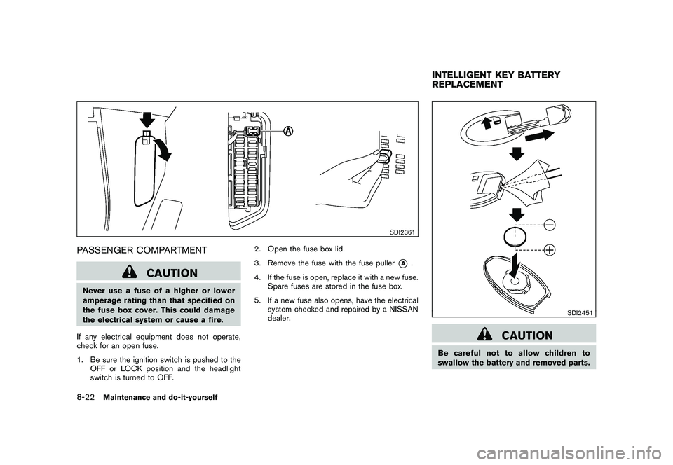
If any electrical equipment does not operate,
check for an open fuse.
1. Be sure the ignition switch is pushed to the OFF or LOCK position and the headlight
switch is turned to OFF. 2. Open the fuse box lid.
3. Remove the fuse with the fuse puller
*A
.
4. If the fuse is open, replace it with a new fuse. Spare fuses are stored in the fuse box.
5. If a new fuse also opens, have the electrical system checked and repaired by a NISSAN
dealer.
SDI2451
CAUTION
Be careful not to allow children to
swallow the battery and removed parts.INTELLIGENT KEY BATTERY
REPLACEMENT
8-22
Maintenance and do-it-yourself
Page 361 of 409
Black plate (363,1)
Model "Z34-D" EDITED: 2009/ 9/ 10
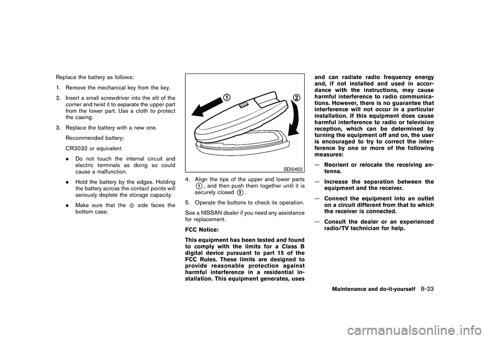
Replace the battery as follows:
1. Remove the mechanical key from the key.
2. Insert a small screwdriver into the slit of thecorner and twist it to separate the upper part
from the lower part. Use a cloth to protect
the casing.
3. Replace the battery with a new one. Recommended battery:
CR2032 or equivalent
.Do not touch the internal circuit and
electric terminals as doing so could
cause a malfunction.
. Hold the battery by the edges. Holding
the battery across the contact points will
seriously deplete the storage capacity.
. Make sure that the +side faces the
bottom case.
SDI2452
4. Align the tips of the upper and lower parts
*1, and then push them together until it is
securely closed
*2.
5. Operate the buttons to check its operation.
See a NISSAN dealer if you need any assistance
for replacement.
FCC Notice:
This equipment has been tested and found
to comply with the limits for a Class B
digital device pursuant to part 15 of the
FCC Rules. These limits are designed to
provide reasonable protection against
harmful interference in a residential in-
stallation. This equipment generates, uses and can radiate radio frequency energy
and, if not installed and used in accor-
dance with the instructions, may cause
harmful interference to radio communica-
tions. However, there is no guarantee that
interference will not occur in a particular
installation. If this equipment does cause
harmful interference to radio or television
reception, which can be determined by
turning the equipment off and on, the user
is encouraged to try to correct the inter-
ference by one or more of the following
measures:
—
Reorient or relocate the receiving an-
tenna.
— Increase the separation between the
equipment and the receiver.
— Connect the equipment into an outlet
on a circuit different from that to which
the receiver is connected.
— Consult the dealer or an experienced
radio/TV technician for help.
Maintenance and do-it-yourself
8-23