2010 MERCEDES-BENZ SLK55AMG ESP
[x] Cancel search: ESPPage 268 of 312
i
This procedure does not arm the anti-
theft alarm system, nor does it lock the fuel
filler flap and the storage compartments. Manually unlocking the gear selector
lever
If the vehicle’s electrical system is
malfunctioning, the gear selector lever could
remain locked in park position P. In this case
the gear selector lever can be unlocked
manually, e.g. to tow the vehicle.
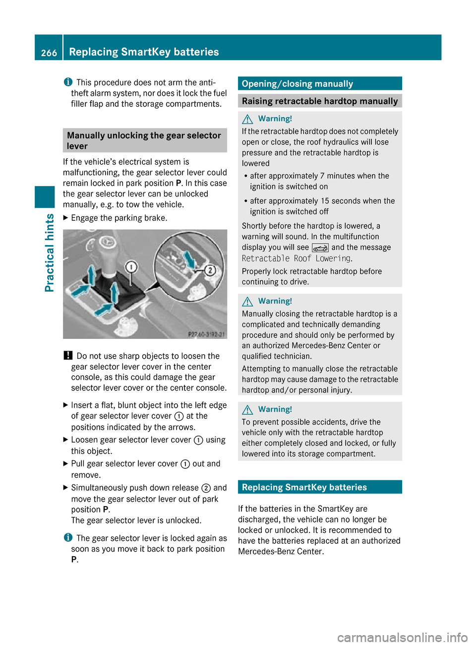
X Engage the parking brake. !
Do not use sharp objects to loosen the
gear selector lever cover in the center
console, as this could damage the gear
selector lever cover or the center console.
X Insert a flat, blunt object into the left edge
of gear selector lever cover : at the
positions indicated by the arrows.
X Loosen gear selector lever cover : using
this object.
X Pull gear selector lever cover : out and
remove.
X Simultaneously push down release ; and
move the gear selector lever out of park
position P.
The gear selector lever is unlocked.
i The gear selector lever is locked again as
soon as you move it back to park position
P. Opening/closing manually
Raising retractable hardtop manually
G
Warning!
If the retractable hardtop does not completely
open or close, the roof hydraulics will lose
pressure and the retractable hardtop is
lowered
R after approximately 7 minutes when the
ignition is switched on
R after approximately 15 seconds when the
ignition is switched off
Shortly before the hardtop is lowered, a
warning will sound. In the multifunction
display you will see K and the message
Retractable Roof Lowering.
Properly lock retractable hardtop before
continuing to drive. G
Warning!
Manually closing the retractable hardtop is a
complicated and technically demanding
procedure and should only be performed by
an authorized Mercedes-Benz Center or
qualified technician.
Attempting to manually close the retractable
hardtop may cause damage to the retractable
hardtop and/or personal injury. G
Warning!
To prevent possible accidents, drive the
vehicle only with the retractable hardtop
either completely closed and locked, or fully
lowered into its storage compartment. Replacing SmartKey batteries
If the batteries in the SmartKey are
discharged, the vehicle can no longer be
locked or unlocked. It is recommended to
have the batteries replaced at an authorized
Mercedes-Benz Center. 266
Replacing SmartKey batteriesPractical hints
171_AKB; 3; 60, en-US
d2ureepe,
Version: 2.11.8.1 2009-05-11T16:00:23+02:00 - Seite 266
Page 274 of 312
!
To avoid damage to the hood, the wiper
arms should only be folded forward when
in the vertical position.
! Never open the hood when a wiper arm is
folded forward.
Hold on to the wiper when folding a wiper
arm back. If released, the force of the
impact from the tensioning spring could
crack the windshield.
Do not allow a wiper arm to contact the
windshield glass without a wiper blade
inserted.
Mercedes-Benz recommends that you have
this work carried out at an authorized
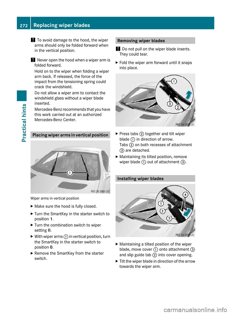
Mercedes-Benz Center. Placing wiper arms in vertical position
Wiper arms in vertical position
X
Make sure the hood is fully closed.
X Turn the SmartKey in the starter switch to
position 1.
X Turn the combination switch to wiper
setting II.
X With wiper arms : in vertical position, turn
the SmartKey in the starter switch to
position 0.
X Remove the SmartKey from the starter
switch. Removing wiper blades
! Do not pull on the wiper blade inserts.
They could tear.
X Fold the wiper arm forward until it snaps
into place. X
Press tabs ; together and tilt wiper
blade : in direction of arrow.
Tabs ; on both recesses of attachment
= are detached.
X Maintaining its tilted position, remove
wiper blade : out of attachment =. Installing wiper blades
X
Maintaining a tilted position of the wiper
blade, move cover : onto attachment =
and slip guide tab ; into cover opening.
X Tilt the wiper blade in direction of the arrow
towards the wiper arm. 272
Replacing wiper bladesPractical hints
171_AKB; 3; 60, en-US
d2ureepe,
Version: 2.11.8.1 2009-05-11T16:00:23+02:00 - Seite 272
Page 275 of 312
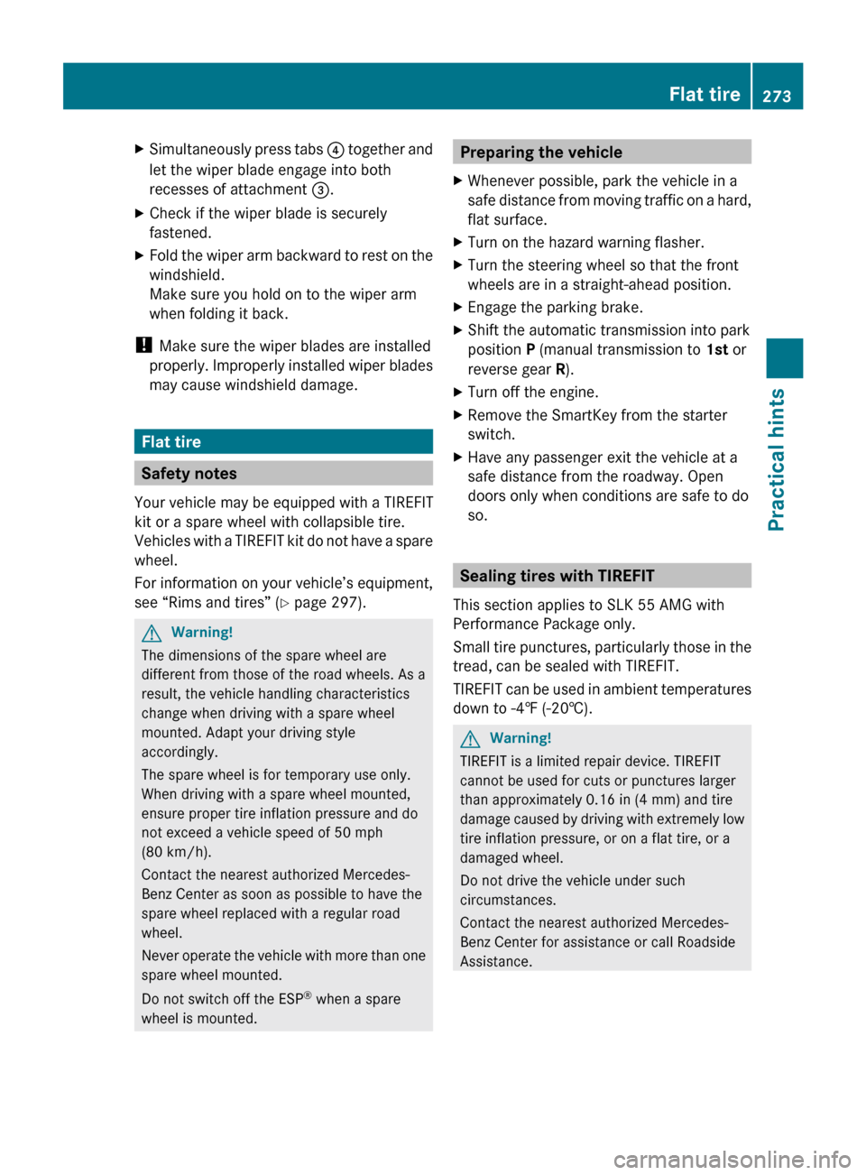
X
Simultaneously press tabs ? together and
let the wiper blade engage into both
recesses of attachment =.
X Check if the wiper blade is securely
fastened.
X Fold the wiper arm backward to rest on the
windshield.
Make sure you hold on to the wiper arm
when folding it back.
! Make sure the wiper blades are installed
properly.
Improperly installed wiper blades
may cause windshield damage. Flat tire
Safety notes
Your vehicle may be equipped with a TIREFIT
kit or a spare wheel with collapsible tire.
Vehicles
with a TIREFIT kit do not have a spare
wheel.
For information on your vehicle’s equipment,
see “Rims and tires” ( Y page 297).G
Warning!
The dimensions of the spare wheel are
different from those of the road wheels. As a
result, the vehicle handling characteristics
change when driving with a spare wheel
mounted. Adapt your driving style
accordingly.
The spare wheel is for temporary use only.
When driving with a spare wheel mounted,
ensure proper tire inflation pressure and do
not exceed a vehicle speed of 50 mph
(80 km/h).
Contact the nearest authorized Mercedes-
Benz Center as soon as possible to have the
spare wheel replaced with a regular road
wheel.
Never
operate the vehicle with more than one
spare wheel mounted.
Do not switch off the ESP ®
when a spare
wheel is mounted. Preparing the vehicle
X Whenever possible, park the vehicle in a
safe
distance from moving traffic on a hard,
flat surface.
X Turn on the hazard warning flasher.
X Turn the steering wheel so that the front
wheels are in a straight-ahead position.
X Engage the parking brake.
X Shift the automatic transmission into park
position P (manual transmission to 1st or
reverse gear R).
X Turn off the engine.
X Remove the SmartKey from the starter
switch.
X Have any passenger exit the vehicle at a
safe distance from the roadway. Open
doors only when conditions are safe to do
so. Sealing tires with TIREFIT
This section applies to SLK 55 AMG with
Performance Package only.
Small
tire punctures, particularly those in the
tread, can be sealed with TIREFIT.
TIREFIT can be used in ambient temperatures
down to -4‡ (-20†). G
Warning!
TIREFIT is a limited repair device. TIREFIT
cannot be used for cuts or punctures larger
than approximately 0.16 in (4 mm) and tire
damage
caused by driving with extremely low
tire inflation pressure, or on a flat tire, or a
damaged wheel.
Do not drive the vehicle under such
circumstances.
Contact the nearest authorized Mercedes-
Benz Center for assistance or call Roadside
Assistance. Flat tire
273
Practical hints
171_AKB; 3; 60, en-US
d2ureepe, Version: 2.11.8.1 2009-05-11T16:00:23+02:00 - Seite 273 Z
Page 276 of 312
X
Foreign objects (e.g. screws or nails)
should not be removed from the tire.
X Take the TIREFIT kit, the sticker, and the
electric air pump out of the
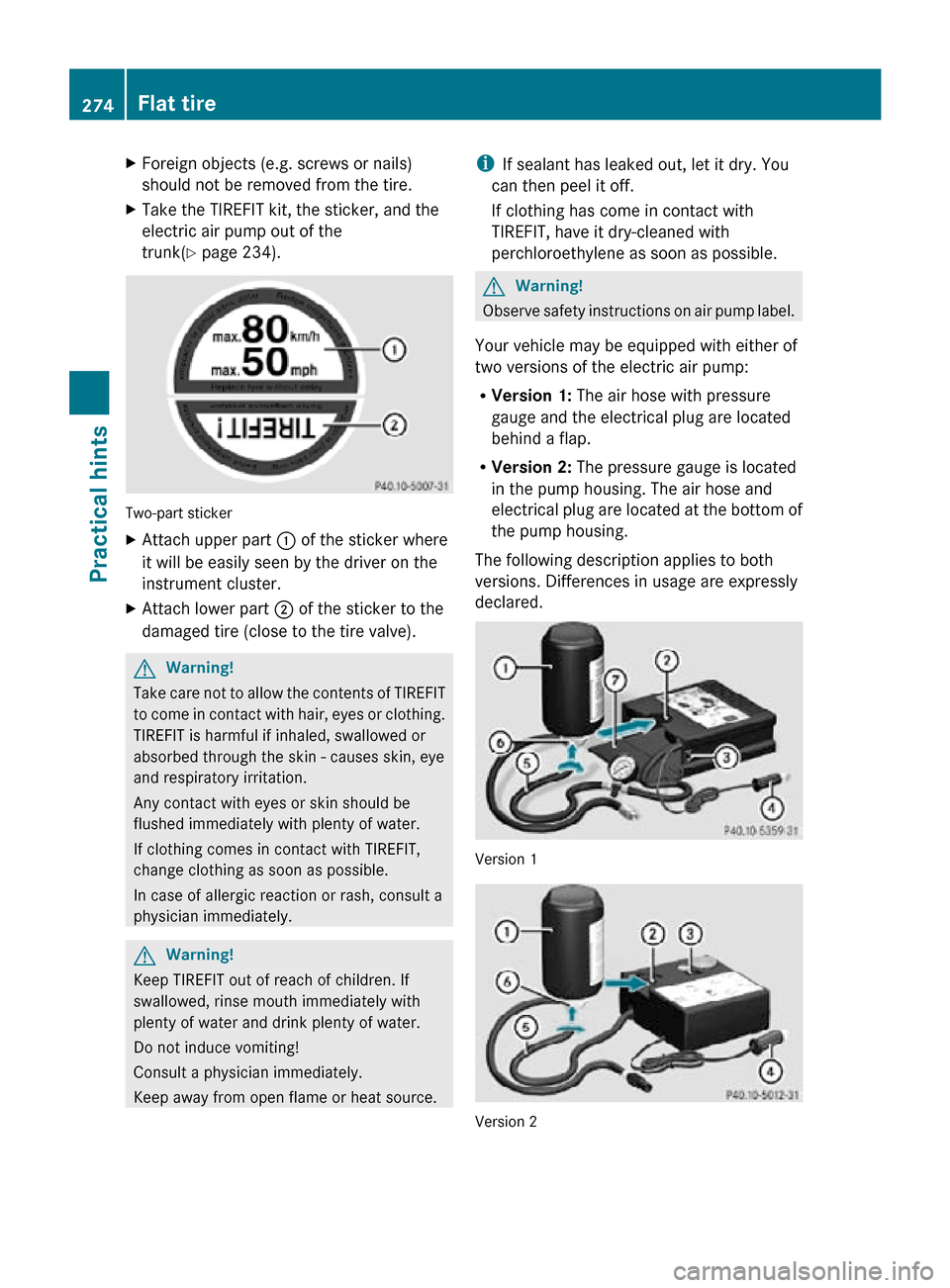
trunk(Y page 234). Two-part sticker
X
Attach upper part : of the sticker where
it will be easily seen by the driver on the
instrument cluster.
X Attach lower part ; of the sticker to the
damaged tire (close to the tire valve). G
Warning!
Take care not to allow the contents of TIREFIT
to come in contact with hair, eyes or clothing.
TIREFIT is harmful if inhaled, swallowed or
absorbed through the skin - causes skin, eye
and respiratory irritation.
Any contact with eyes or skin should be
flushed immediately with plenty of water.
If clothing comes in contact with TIREFIT,
change clothing as soon as possible.
In case of allergic reaction or rash, consult a
physician immediately. G
Warning!
Keep TIREFIT out of reach of children. If
swallowed, rinse mouth immediately with
plenty of water and drink plenty of water.
Do not induce vomiting!
Consult a physician immediately.
Keep away from open flame or heat source. i
If sealant has leaked out, let it dry. You
can then peel it off.
If clothing has come in contact with
TIREFIT, have it dry-cleaned with
perchloroethylene as soon as possible. G
Warning!
Observe safety instructions on air pump label.
Your vehicle may be equipped with either of
two versions of the electric air pump:
R Version 1: The air hose with pressure
gauge and the electrical plug are located
behind a flap.
R Version 2: The pressure gauge is located
in the pump housing. The air hose and
electrical plug are located at the bottom of
the pump housing.
The following description applies to both
versions. Differences in usage are expressly
declared. Version 1
Version 2274
Flat tirePractical hints
171_AKB; 3; 60, en-US
d2ureepe,
Version: 2.11.8.1 2009-05-11T16:00:23+02:00 - Seite 274
Page 279 of 312
Mounting the spare wheel
Introduction X
Prepare the vehicle as described
(Y page 273).
X Take the following out of the vehicle:
R
spare wheel
R jack
R wheel wrench
R collapsible wheel chock
R wheel bolts for spare wheel
R alignment bolt
R electric air pump
For information on where to find the
respective items, see “Where will I find ...?”
(Y page 234) and ( Y page 235).
i Vehicles without spare wheel are not
factory-equipped
with the tools required for
a wheel change such as a jack or a wheel
wrench. Some tools required for a wheel
change are specific to your vehicle.
Contact an authorized Mercedes-Benz
Center to obtain the tools approved for
your vehicle. This section describes the
wheel change using the tools approved and
recommended for your vehicle.
Lifting the vehicle G
Warning!
When jacking up the vehicle, only use the jack
which has been specifically approved by
Mercedes-Benz for your vehicle.
The
jack is designed exclusively for jacking up
the vehicle at the jack take-up brackets built
into both sides of the vehicle. Make sure the
jack arm is fully seated in the jack take-up
bracket. The jack must always be vertical
when in use, especially on inclines or
declines.
The jack is intended only for lifting the vehicle
briefly for wheel changes. It is not suited for
performing maintenance work under the vehicle. To help avoid personal injury, use the
jack only to lift the vehicle during a wheel
change.
Never get beneath the vehicle while it is
supported by the jack. Keep hands and feet
away from the area under the lifted vehicle.
Always lower the vehicle onto sufficient
capacity
jackstands before working under the
vehicle.
Always engage the parking brake firmly and
block the wheels with wheel chocks or other
sizeable objects before raising the vehicle
with the jack. Do not disengage the parking
brake while the vehicle is raised.
Make sure that the ground on which the
vehicle is standing and where you place the
jack is solid, level and not slippery. If
necessary, use a large underlay. On slippery
surfaces, such as tiled floors, you should use
a non-slip underlay, for example a rubber mat.
Do not use wooden blocks or similar objects
to support the jack. Otherwise the jack may
not be able to achieve its load-bearing
capacity if it is not at its full height.
Never start the engine when the vehicle is
raised.
Also observe the notes on the jack.
X Prevent the vehicle from rolling away by
blocking
wheels with wheel chocks or other
sizeable objects.
When your vehicle is equipped with a wheel
chock, it is included with the vehicle tool kit
(Y page 234). For information on setting up
the collapsible wheel chock, see
(Y page 234).
When changing a wheel on a level surface:
X Place a wheel chock or other sizeable
object
in front of and another wheel chock
or other sizeable object behind the wheel
that is diagonally opposite to the wheel
being changed. Flat tire
277
Practical hints
171_AKB; 3; 60, en-US
d2ureepe, Version: 2.11.8.1 2009-05-11T16:00:23+02:00 - Seite 277 Z
Page 284 of 312

loose if they are not tightened to a torque of
80 lb-ft (110 Nm).
X Fully collapse the jack, with handle folded
in (storage position), see ( Y page 235).
X Store the jack and the other vehicle tools
in the designated storage space.
X If so equipped, wrap the damaged wheel in
the protective wrap provided with the
vehicle tool kit and put the wheel in the
trunk.
The retractable hardtop must be closed.
For information on storing the spare wheel
after it has been replaced by a regular road
wheel, see ( Y page 235). Battery
Safety notes
A battery should always be sufficiently
charged in order to achieve its rated service
life. Refer to Maintenance Booklet for battery
maintenance intervals.
If you use your vehicle mostly for short-
distance trips, you will need to have the
battery charge checked more frequently.
When replacing a battery, always use a
battery approved by Mercedes-Benz.
If you do not intend to operate your vehicle
for an extended period of time, contact an
authorized Mercedes-Benz Center about
steps you need to observe. G
Warning!
Observe all safety instructions and
precautions when handling automotive
batteries.Risk of explosion.
Fire, open flames and
smoking are prohibited
when handling batteries.
Avoid creating sparks.
Battery acid is caustic. Do
not allow it to come into
contact with skin, eyes or
clothing.
Wear suitable protective
clothing, especially gloves,
apron and faceguard.
Wear eye protection.
Rinse any acid spills
immediately with clear
water. Contact a physician
if necessary.
Keep children away.
Follow the instructions in
this Operator’s Manual.
A battery contains materials that can harm
the environment if disposed of improperly. A
large 12 V storage battery contains lead.
Recycling of the battery is the preferred
method of disposal. Many states (USA only)
or provinces (Canada only) require sellers of
batteries to accept the old battery for
recycling.
G Warning!
Failure to follow these instructions can result
in severe injury or death.
Never lean over batteries while connecting.
You might get injured.
Battery fluid contains sulfuric acid. Do not
allow this fluid to come in contact with eyes,
skin or clothing. In case it does, immediately
flush affected area with water and seek
medical help if necessary.
A battery will also produce hydrogen gas,
which is flammable and explosive. Keep
flames or sparks away from battery, avoid
improper connection of jumper cables,
smoking etc.
282 Battery
Practical hints
171_AKB; 3; 60, en-US
d2ureepe,
Version: 2.11.8.1 2009-05-11T16:00:23+02:00 - Seite 282
Page 289 of 312
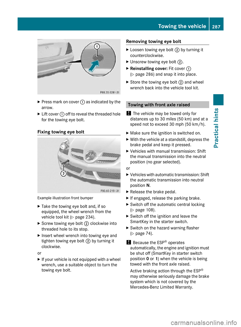
X
Press mark on cover : as indicated by the
arrow.
X Lift cover : off to reveal the threaded hole
for the towing eye bolt.
Fixing towing eye bolt Example illustration front bumper
X
Take the towing eye bolt and, if so
equipped, the wheel wrench from the
vehicle tool kit (Y page 234).
X Screw towing eye bolt ; clockwise into
threaded hole to its stop.
X Insert wheel wrench into towing eye and
tighten towing eye bolt ; by turning it
clockwise.
or
X If your vehicle is not equipped with a wheel
wrench, use a suitable object to turn the
towing eye bolt. Removing towing eye bolt X
Loosen towing eye bolt ; by turning it
counterclockwise.
X Unscrew towing eye bolt ;.
X Reinstalling cover: Fit cover :
(Y page 286) and snap it into place.
X Store the towing eye bolt ; and wheel
wrench back into the vehicle tool kit. Towing with front axle raised
! The vehicle may be towed only for
distances up to 30 miles (50 km) and at a
speed not to exceed 30 mph (50 km/h).
X Make sure the ignition is switched on.
X With the vehicle at a standstill, depress the
brake pedal and keep it pressed.
X Vehicles with manual transmission: Shift
the manual transmission into the neutral
position (no gear selected).
or
X Vehicles with automatic transmission: Shift
the automatic transmission into neutral
position N.
X Release the brake pedal.
X If engaged, release the parking brake.
X Switch off the automatic central locking
(Y page 108).
X Switch off the ignition and leave the
SmartKey in the starter switch.
X Switch on the hazard warning flasher
(Y page 74).
! Because the ESP ®
operates
automatically, the engine and ignition must
be shut off (SmartKey in starter switch
position 0 or 1) when the vehicle is being
towed with the front axle raised.
Active braking action through the ESP ®
may otherwise seriously damage the brake
system which is not covered by the
Mercedes-Benz Limited Warranty. Towing the vehicle
287Practical hints
171_AKB; 3; 60, en-US
d2ureepe, Version: 2.11.8.1 2009-05-11T16:00:23+02:00 - Seite 287 Z
Page 296 of 312
Vehicle specification SLK 300
(171.454)
The quoted data apply only to the standard
vehicle. Contact an authorized Mercedes-
Benz
Center for the corresponding data of all
special bodies and special equipment. Engine SLK 300
Engine, type
272
Mode of operation
4-stroke engine,
gasoline injection No. of cylinders
6
Bore
3.46 in (88.00 mm)
Stroke
3.23 in (82.10 mm)
Total piston
displacement
182.8 cu in
(2 996 cm 3
) Compression
ratio
11.3:1
Output acc. to
SAE J 1349
17 228 hp/6
100 rpm
(170 kW/6 100 rpm) Maximum torque
acc.
to SAE J 1349 221 lb-ft/
2 500 - 5 000 rpm
(300 Nm/
2 500 - 5 000 rpm) Maximum engine
speed
6 500 rpm
Firing order
1-4-3-6-2-5
Poly-V-belt
2 401 mm
Electrical system SLK 300
Alternator
14 V/150 A
Starter motor
12 V/1.4 kW
Battery
12 V/74 Ah Electrical system SLK 300
Spark plugs, type
Bosch Y 7 MPP33
Spark plugs,
electrode gap
0.031 in (0.8 mm)
Spark plugs,
tightening torque
15 - 18 lb-ft
(20 - 25 Nm) Main dimensions SLK 300
Overall vehicle
length
161.7 in (4
107 mm) Overall vehicle
width
18 79.2 in (2
012 mm) Overall vehicle
height
51.0 in (1
296 mm) 60.8 in (1
545 mm) 19 Wheelbase
95.7 in (2
430 mm) Track, front
60.2 in (1
530 mm) Track, rear
61.0 in (1
549 mm) Turning circle
34.5 ft (10.5 m)
Weights SLK 300
Roof load
max. 110 lb (50 kg)
Trunk load
max. 220 lb (100 kg)
!
This
vehicle is not designed to carry items
on its roof. Roof rails and any roof-mounted
devices, unless expressly approved by
Mercedes-Benz for use on this vehicle
model, must not be used as they will
damage the vehicle and retractable
hardtop.
At time of printing, Mercedes-Benz does
not offer any roof racks or any other roof-
mounted devices for use on this vehicle.
17 Premium fuel required. Performance may vary with fuel octane rating.
18 Exterior rear view mirrors folded out.
19 When opening/closing hardtop. 294
Vehicle specification SLK 300 (171.454)
Technical data
171_AKB; 3; 60, en-US
d2ureepe,
Version: 2.11.8.1 2009-05-11T16:00:23+02:00 - Seite 294