2010 MERCEDES-BENZ SLK300 tow
[x] Cancel search: towPage 89 of 312
Transmission positions
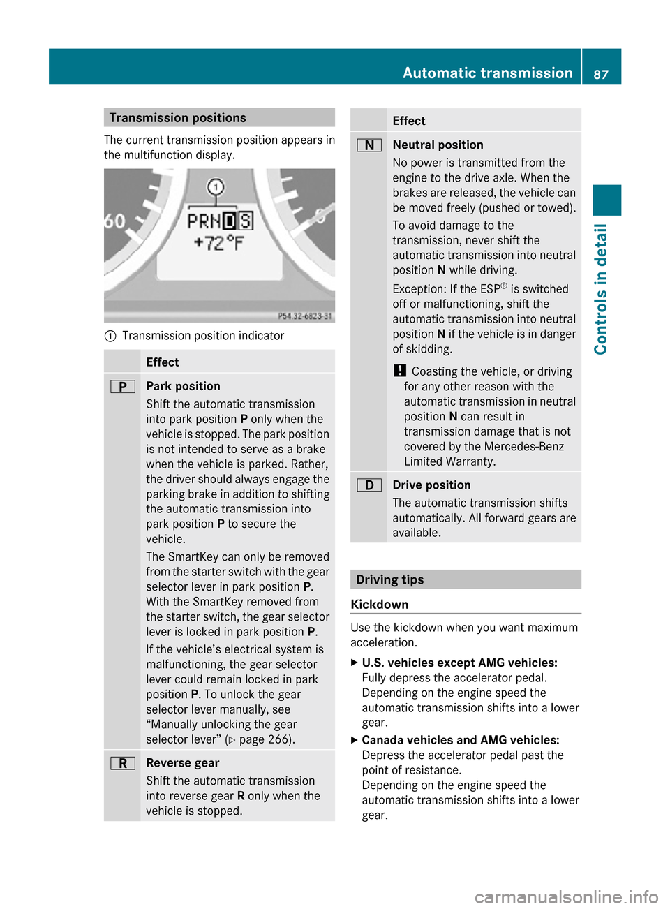
The current transmission position appears in
the multifunction display. :
Transmission position indicator Effect
B
Park position
Shift the automatic transmission
into park position P only when the
vehicle is stopped. The park position
is not intended to serve as a brake
when the vehicle is parked. Rather,
the driver should always engage the
parking brake in addition to shifting
the automatic transmission into
park position P to secure the
vehicle.
The SmartKey can only be removed
from the starter switch with the gear
selector lever in park position P.
With the SmartKey removed from
the starter switch, the gear selector
lever is locked in park position
P.
If the vehicle’s electrical system is
malfunctioning, the gear selector
lever could remain locked in park
position P. To unlock the gear
selector lever manually, see
“Manually unlocking the gear
selector lever” ( Y page 266). C
Reverse gear
Shift the automatic transmission
into reverse gear R only when the
vehicle is stopped. Effect
A
Neutral position
No power is transmitted from the
engine to the drive axle. When the
brakes are released, the vehicle can
be moved freely (pushed or towed).
To avoid damage to the
transmission, never shift the
automatic transmission into neutral
position N while driving.
Exception: If the ESP ®
is switched
off or malfunctioning, shift the
automatic transmission into neutral
position N if the vehicle is in danger
of skidding.
! Coasting the vehicle, or driving
for any other reason with the
automatic transmission in neutral
position N can result in
transmission damage that is not
covered by the Mercedes-Benz
Limited Warranty. 7
Drive position
The automatic transmission shifts
automatically. All forward gears are
available.
Driving tips
Kickdown Use the kickdown when you want maximum
acceleration.
X
U.S. vehicles except AMG vehicles:
Fully depress the accelerator pedal.
Depending on the engine speed the
automatic transmission shifts into a lower
gear.
X Canada vehicles and AMG vehicles:
Depress the accelerator pedal past the
point of resistance.
Depending on the engine speed the
automatic transmission shifts into a lower
gear. Automatic transmission
87Controls in detail
171_AKB; 3; 60, en-US
d2ureepe, Version: 2.11.8.1 2009-05-11T16:00:23+02:00 - Seite 87 Z
Page 120 of 312
X
Adjusting: Turn rotary control :.
The volume will increase or decrease
depending on the direction turned.
Adjusting volume for telephone calls
In hands-free mode, you can adjust the
volume of a telephone call while the call is
currently active.
During a telephone call:
X Turn rotary control :.
The volume will increase or decrease
depending on the direction turned.
i The volume of the audio system or a
telephone call can also be adjusted by
pressing the button W or X on the
multifunction steering wheel ( Y page 94).
Sound X
Switching on/off: Press button 8 on
the audio control unit (Y page 113).
The sound of the current audio source is
switched on or off.
i When the sound is switched off, the
symbol 8 appears in the status line.
If you change the audio source, or alter the
volume, the sound is automatically
switched on again.
In CD and MP3 mode, button 8
switches the pause function on or off.
Selecting sound settings You can select different bass and treble
settings for each individual audio source. The
particular
Sound menu can be opened from
the basic menu for the desired operating
mode, or by pressing the button J on the
audio control unit.
Example:
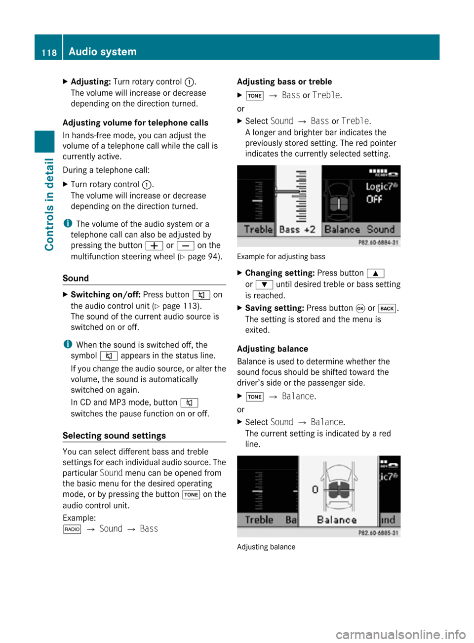
$ Q Sound Q Bass Adjusting bass or treble
X
J Q Bass or Treble.
or
X Select Sound Q Bass or Treble.
A longer and brighter bar indicates the
previously stored setting. The red pointer
indicates the currently selected setting. Example for adjusting bass
X
Changing setting: Press button 9
or : until desired treble or bass setting
is reached.
X Saving setting: Press button 9 or k.
The setting is stored and the menu is
exited.
Adjusting balance
Balance is used to determine whether the
sound focus should be shifted toward the
driver’s side or the passenger side.
X J Q Balance.
or
X Select Sound Q Balance.
The current setting is indicated by a red
line. Adjusting balance118
Audio systemControls in detail
171_AKB; 3; 60, en-US
d2ureepe,
Version: 2.11.8.1 2009-05-11T16:00:23+02:00 - Seite 118
Page 183 of 312
system. Spoken commands are not
available.
A voice connection between the Roadside
Assistance dispatcher and the occupants of
the vehicle will be established.
X Describe the nature of the need for
assistance.
The Mercedes-Benz Roadside Assistance
dispatcher will either dispatch a qualified
Mercedes-Benz technician or arrange to tow
your vehicle to the nearest authorized
Mercedes-Benz Center. For services such as
labor and/or towing, charges may apply.
Refer to the Roadside Assistance manual for
more information.
Sign and Drive services (USA only):
Services such as a jump start, a few gallons
of fuel or the replacement of a flat tire with
the vehicle spare wheel are obtainable at no
charge.
i If the indicator lamp in Roadside
Assistance button : is flashing
continuously and there was no voice
connection to the Customer Assistance
Center established, then the Tele Aid
system could not initiate a Roadside
Assistance call (e.g. the relevant cellular
phone network is not available). The
message Call Failed appears in the
multifunction display.
X Terminating calls: Press button ~ on
the multifunction steering wheel.
or
X Press the respective button for ending a
telephone call on the audio system or the
COMAND system.
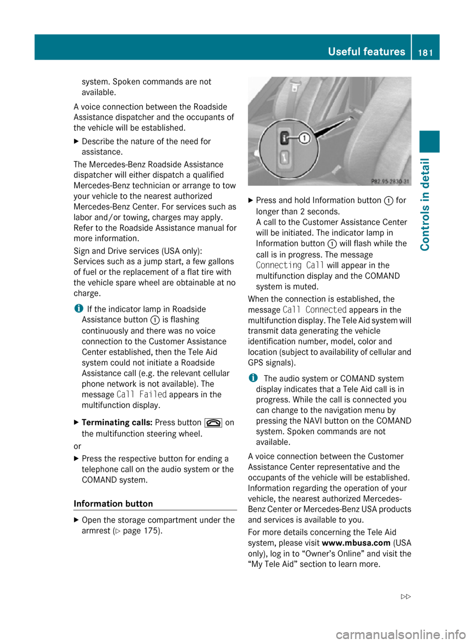
Information button X
Open the storage compartment under the
armrest (Y page 175). X
Press and hold Information button : for
longer than 2 seconds.
A call to the Customer Assistance Center
will be initiated. The indicator lamp in
Information button : will flash while the
call is in progress. The message
Connecting Call will appear in the
multifunction display and the COMAND
system is muted.
When the connection is established, the
message Call Connected appears in the
multifunction display. The Tele Aid system will
transmit data generating the vehicle
identification number, model, color and
location (subject to availability of cellular and
GPS signals).
i The audio system or COMAND system
display indicates that a Tele Aid call is in
progress. While the call is connected you
can change to the navigation menu by
pressing the NAVI button on the COMAND
system. Spoken commands are not
available.
A voice connection between the Customer
Assistance Center representative and the
occupants of the vehicle will be established.
Information regarding the operation of your
vehicle, the nearest authorized Mercedes-
Benz Center or Mercedes-Benz USA products
and services is available to you.
For more details concerning the Tele Aid
system, please visit www.mbusa.com (USA
only), log in to “Owner’s Online” and visit the
“My Tele Aid” section to learn more. Useful features
181Controls in detail
171_AKB; 3; 60, en-US
d2ureepe, Version: 2.11.8.1 2009-05-11T16:00:23+02:00 - Seite 181 Z
Page 185 of 312
(1-800-367-6372) (USA only) or
1-888-923-8367
(Canada only).
You will be asked to provide your password.
X Then return to your vehicle at the time
arranged with the Customer Assistance
Center and pull the trunk recessed handle
for a minimum of 20 seconds until the
indicator
lamp in the SOS button is flashing.
The message Connecting Call appears in
the multifunction display.
As an alternative, you may unlock the vehicle
via Internet in the “My Tele Aid” section of
“Owner’s
Online”, using your ID and password
(USA only).
i The remote door unlock feature is
available if the relevant cellular phone
network is available.
The SOS button will flash and the message
Connecting Call will appear in the
multifunction display to indicate receipt of
the door unlock command.
If the trunk recessed handle was pulled for
more than 20 seconds before door unlock
authorization was received by the
Customer Assistance Center, you must
wait 15 minutes before pulling the trunk
recessed handle again.
Stolen Vehicle Recovery Services In the event your vehicle was stolen:
X
Report the incident to the police.
The police will issue a numbered incident
report.
X Pass this number on to the Customer
Assistance Center along with your
password.
The Customer Assistance Center will then
attempt to covertly contact the vehicle’s
Tele Aid system. Once the vehicle is
located, the Customer Assistance Center
will contact the local law enforcement and
you. The vehicle’s location will only be
provided to law enforcement.
i If the anti-theft alarm or the tow-away
alarm stays on for more than 30 seconds, a call to the Customer Assistance Center is
initiated automatically by the Tele Aid
system provided Tele Aid service was
subscribed to and properly activated, and
that necessary cellular service and GPS
coverage are available. See “Anti-theft
alarm system”
(Y page 51) and “Tow-away
alarm” ( Y page 52). Garage door opener
The
integrated remote control can operate up
to three separately controlled devices
compatible with HomeLink ®
or some other
systems. G
Warning!
Before programming the integrated remote
control to a garage door opener or gate
operator, make sure people and objects are
out of the way of the device to prevent
potential harm or damage. When
programming
a garage door opener, the door
moves up or down. When programming a gate
operator, the gate opens or closes.
Do not use the integrated remote control with
any garage door opener that lacks safety stop
and reverse features as required by U.S.
federal safety standards (this includes any
garage door opener model manufactured
before April 1, 1982). A garage door that
cannot detect an object - signaling the door
to stop and reverse - does not meet current
U.S. federal safety standards.
When programming a garage door opener,
park vehicle outside the garage.
Do not run the engine while programming the
integrated remote control. Inhalation of
exhaust gas is hazardous to your health. All
exhaust gas contains carbon monoxide (CO),
and inhaling it can cause unconsciousness
and possible death. Useful features
183
Controls in detail
171_AKB; 3; 60, en-US
d2ureepe, Version: 2.11.8.1 2009-05-11T16:00:23+02:00 - Seite 183 Z
Page 193 of 312

fuel is not covered by the Mercedes-Benz
Limited Warranty.
! If you have accidentally filled the tank
with incorrect or non-approved fuel, do not
switch on the ignition. Otherwise the
incorrect or non-approved fuel will get into
the fuel lines. The fuel system must be
drained completely. Contact an authorized
Mercedes-Benz Center to have the fuel
system drained completely.
! To prevent damage to the catalytic
converters, only use premium unleaded
gasoline in this vehicle.
Any noticeable irregularities in engine
operation should be repaired promptly.
Otherwise, excessive unburned fuel may
reach the catalytic converter, causing it to
overheat and potentially start a fire.
i Only use premium unleaded gasoline with
a minimum Posted Octane Rating of 91
(average of 96 RON/86 MON).
Information on gasoline quality can
normally be found on the fuel pump. Please
contact gas station personnel in case
labels on the pump cannot be found.
For more information on gasoline, see
“Premium unleaded gasoline”
(Y page 303), see “Fuel requirements”
(Y page 303), or contact an authorized
Mercedes-Benz Center, or visit
www.mbusa.com (USA only).
Locking/unlocking the vehicle with the
SmartKey automatically locks/unlocks the
fuel filler flap.
i In case the central locking system does
not release the fuel filler flap, or the
opening mechanism is clamping, contact
Roadside Assistance or an authorized
Mercedes-Benz Center.
The fuel filler flap is located on the right-hand
side of the vehicle towards the rear. X
Turn off the engine.
i Leaving the engine running and the fuel
filler cap open can cause the yellow fuel
tank reserve warning lamp to flash and the
malfunction indicator lamp ! (USA
only) or ; (Canada only) to illuminate.
For more information, see also “Practical
hints” (Y page 262).
X Remove the SmartKey from the starter
switch.
X Opening: Press fuel filler flap : at the
point indicated by the arrow.
X Turn fuel filler cap ; counterclockwise.
X Take off fuel filler cap ;.
X Place fuel filler cap ; in direction of arrow
into holder =.
X Fully insert filler nozzle unit and refuel.
X Only fill your tank until the filler nozzle unit
cuts out – do not top off or overfill .
X Closing: Turn fuel filler cap ; clockwise
until it audibly engages.
i Close the fuel filler flap before locking the
vehicle. Otherwise the flap locking pin will
prevent closing the fuel filler flap.
X Close fuel filler flap :. Check regularly and before a long trip
For information on quantities and
requirements of operating agents, see “Fuels,
coolants, lubricants, etc.” (Y page 300). At the gas station
191Operation
171_AKB; 3; 60, en-US
d2ureepe, Version: 2.11.8.1 2009-05-11T16:00:23+02:00 - Seite 191 Z
Page 200 of 312
the tires have sustained damage, replace
them.
When replacing rims, only use genuine
Mercedes-Benz wheel bolts specified for the
particular
rim type. Failure to do so can result
in the bolts loosening and possibly an
accident.
Retreaded tires are not tested or
recommended by Mercedes-Benz, since
previous damage cannot always be
recognized on retreads. The operating safety
of the vehicle cannot be assured when such
tires are used. G
Warning!
If you feel a sudden significant vibration or
ride
disturbance, or you suspect that possible
damage to your vehicle has occurred, you
should turn on the hazard warning flashers,
carefully slow down, and drive with caution to
an area which is a safe distance from the road.
Inspect the tires and the vehicle underbody
for possible damage. If the vehicle or tires
appear unsafe, have the vehicle towed to the
nearest authorized Mercedes-Benz Center or
tire dealer for repairs. G
Warning!
Do not drive with a flat tire. A flat tire affects
the ability to steer or brake the vehicle. You
could lose control of the vehicle. Continued
driving
with a flat tire or driving at high speed
with a flat tire will cause excessive heat build-
up and possibly a fire. Important guidelines
R Only
use sets of tires and rims of the same
type and make.
R Tires must be of the correct size for the rim.
R Break in new tires for approximately
60 miles (100 km) at moderate speeds.
R Regularly check the tires and rims for
damage. Dented or bent rims can cause tire inflation pressure loss and damage to the
tire beads.
R If the vehicle is heavily loaded, check tire
inflation pressure and correct as required.
R Do not allow your tires to wear down too
far. Adhesion properties on wet roads are
sharply reduced at tread depths of less
than 1
/ 8 in (3 mm).
R When
replacing individual tires, you should
mount new tires on the front wheels first
(on vehicles with same-sized wheels all
around). Recommended tire inflation pressure
G
Warning!
Follow recommended tire inflation pressures.
Do not underinflate tires. Underinflated tires
wear excessively and/or unevenly, adversely
affect handling and fuel economy, and are
more likely to fail from being overheated.
Do
not overinflate tires. Overinflated tires can
adversely affect handling and ride comfort,
wear unevenly, increase stopping distance,
and result in sudden deflation (blowout)
because they are more likely to become
punctured or damaged by road debris,
potholes etc.
Do not overload the tires by exceeding the
specified load limit as indicated on the Tire
and Loading Information placard on the
driver’s door B-pillar. Overloading the tires
can overheat them, possibly causing a
blowout. Overloading the tires can also result
in handling or steering problems, or brake
failure.
Your vehicle is equipped with the Tire and
Loading Information placard located on the
driver’s door B-pillar ( Y page 205).
The tire inflation pressure should be checked
regularly. Only adjust the tire inflation
pressure on cold tires. The tires can be
considered cold if the vehicle has been
parked for at least 3 hours or driven less than 198
Tires and wheels
Operation
171_AKB; 3; 60, en-US
d2ureepe,
Version: 2.11.8.1 2009-05-11T16:00:23+02:00 - Seite 198
Page 208 of 312
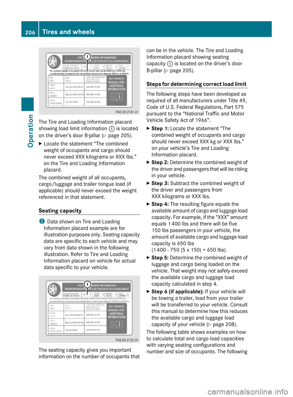
The Tire and Loading Information placard
showing load limit information
: is located
on the driver’s door B-pillar ( Y page 205).
X Locate the statement “The combined
weight of occupants and cargo should
never exceed XXX kilograms or XXX lbs.”
on the Tire and Loading Information
placard.
The combined weight of all occupants,
cargo/luggage and trailer tongue load (if
applicable) should never exceed the weight
referenced in that statement.
Seating capacity i
Data shown on Tire and Loading
Information placard example are for
illustration purposes only. Seating capacity
data are specific to each vehicle and may
vary from data shown in the following
illustration. Refer to Tire and Loading
Information placard on vehicle for actual
data specific to your vehicle. The seating capacity gives you important
information on the number of occupants that can be in the vehicle. The Tire and Loading
Information placard showing seating
capacity
: is located on the driver’s door
B-pillar ( Y page 205).
Steps for determining correct load limit The following steps have been developed as
required of all manufacturers under Title 49,
Code of U.S. Federal Regulations, Part 575
pursuant to the “National Traffic and Motor
Vehicle Safety Act of 1966”.
X
Step 1: Locate the statement “The
combined weight of occupants and cargo
should never exceed XXX kg or XXX lbs.”
on your vehicle’s Tire and Loading
Information placard.
X Step 2: Determine the combined weight of
the driver and passengers that will be riding
in your vehicle.
X Step 3: Subtract the combined weight of
the driver and passengers from
XXX kilograms or XXX lbs.
X Step 4: The resulting figure equals the
available amount of cargo and luggage load
capacity. For example, if the “XXX” amount
equals 1 400 lbs and there will be five
150 lbs passengers in your vehicle, the
amount of available cargo and luggage load
capacity is 650 lbs
(1 400 - 750 (5 x 150) = 650 lbs).
X Step 5: Determine the combined weight of
luggage and cargo being loaded on the
vehicle. That weight may not safely exceed
the available cargo and luggage load
capacity calculated in step 4.
X Step 6 (if applicable): If your vehicle will
be towing a trailer, load from your trailer
will be transferred to your vehicle. Consult
this manual to determine how this reduces
the available cargo and luggage load
capacity of your vehicle ( Y page 208).
The following table shows examples on how
to calculate total and cargo load capacities
with varying seating configurations and
number and size of occupants. The following 206
Tires and wheelsOperation
171_AKB; 3; 60, en-US
d2ureepe,
Version: 2.11.8.1 2009-05-11T16:00:23+02:00 - Seite 206
Page 210 of 312
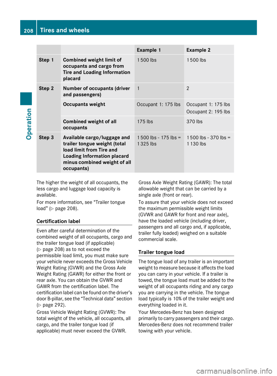
Example 1 Example 2
Step 1 Combined weight limit of
occupants and cargo from
Tire and Loading Information
placard
1 500 lbs 1 500 lbs
Step 2 Number of occupants (driver
and passengers)
1 2
Occupants weight
Occupant 1: 175 lbs Occupant 1: 175 lbs
Occupant 2: 195 lbs
Combined weight of all
occupants
175 lbs 370 lbs
Step 3 Available cargo/luggage and
trailer tongue weight (total
load limit from Tire and
Loading Information placard
minus
combined weight of all
occupants) 1 500 lbs - 175 lbs =
1 325 lbs 1 500 lbs - 370 lbs =
1 130 lbs
The higher the weight of all occupants, the
less cargo and luggage load capacity is
available.
For more information, see “Trailer tongue
load”
(Y page 208).
Certification label Even after careful determination of the
combined
weight of all occupants, cargo and
the trailer tongue load (if applicable)
(Y page 208) as to not exceed the
permissible load limit, you must make sure
your vehicle never exceeds the Gross Vehicle
Weight Rating (GVWR) and the Gross Axle
Weight Rating (GAWR) for either the front or
rear axle. You can obtain the GVWR and
GAWR from the certification label. The
certification label can be found on the driver’s
door B-pillar, see the “Technical data” section
(Y page 292).
Gross Vehicle Weight Rating (GVWR): The
total weight of the vehicle, all occupants, all
cargo, and the trailer tongue load (if
applicable) must never exceed the GVWR. Gross Axle Weight Rating (GAWR): The total
allowable weight that can be carried by a
single axle (front or rear).
To assure that your vehicle does not exceed
the maximum permissible weight limits
(GVWR and GAWR for front and rear axle),
have the loaded vehicle (including driver,
passengers and all cargo and, if applicable,
trailer fully loaded) weighed on a suitable
commercial scale.
Trailer tongue load
The tongue load of any trailer is an important
weight
to measure because it affects the load
you can carry in your vehicle. If a trailer is
towed, the tongue load must be added to the
weight of all occupants riding and any cargo
you are carrying in the vehicle. The tongue
load typically is 10% of the trailer weight and
everything loaded in it.
Your Mercedes-Benz has been designed
primarily to carry passengers and their cargo.
Mercedes-Benz does not recommend trailer
towing with your vehicle. 208
Tires and wheels
Operation
171_AKB; 3; 60, en-US
d2ureepe,
Version: 2.11.8.1 2009-05-11T16:00:23+02:00 - Seite 208