2010 MERCEDES-BENZ S65AMG wheel size
[x] Cancel search: wheel sizePage 429 of 548
Letter “T” preceding the size designation:
Temporary spare tires which are high
pressure compact spares designed for
temporary emergency use only.
Tire width
Tire width : indicates the nominal tire width
in millimeters.
Aspect ratio
Aspect ratio ; is the dimensional
relationship between tire section height and
section width and is expressed in percentage.
The aspect ratio is arrived at by dividing
section height by section width.
Tire code
Tire code = indicates the tire construction
type. The “R” stands for radial tire type. Letter
“D” means diagonal or bias ply construction;
letter “B” means belted-bias ply construction.
At the tire manufacturer’s option, any tire
with a speed capability above 149 mph
(240 km/h) can include a “ZR” in the size
designation (for example: 245/40 ZR 18). For
additional information, see “Tire speed
rating” ( Y page 427).
Rim diameter
Rim diameter ? is the diameter of the bead
seat, not the diameter of the rim edge. The
rim diameter is indicated in inches (in).
Load indexGWarning!
The tire load rating must always be at least
half of the GAWR of your vehicle. Otherwise,
tire failure may be the result which may cause
an accident and/or serious injury to you or
others.
Always replace rims and tires with the same
designation, manufacturer and type as shown
on the original part.
GWarning!
Do not overload the tires by exceeding the
specified load limit as indicated on the Tire
and Loading Information placard on the
driver’s door B-pillar. Overloading the tires
can overheat them, possibly causing a
blowout. Overloading the tires can also result
in handling or steering problems, or brake
failure.
Load index A is a numerical code associated
with the maximum load a tire can support.
For example, a load rating of 91 corresponds
to a maximum load of 1356 lb (615 kg) the
tire is designed to support. See also
“Maximum tire load” (Y page 422) where the
maximum load associated with the load index
is indicated in kilograms and lbs.
For additional information on the load index,
see “Load identification” ( Y page 429).
Speed symbol GWarning!
Even when permitted by law, never operate a
vehicle at speeds greater than the maximum
speed rating of the tires.
Exceeding the maximum speed for which tires
are rated can lead to sudden tire failure,
causing loss of vehicle control and possibly
resulting in an accident and/or serious
personal injury and possible death, for you
and for others.
Regardless of the tire speed rating, local
speed limits should be obeyed. Use prudent
driving speeds appropriate to prevailing
conditions.
Speed symbol B indicates the approved
maximum speed (tire speed rating) for the
tire.
Summer tires
IndexSpeed ratingQup to 100 mph (160 km/h)Rup to 106 mph (170 km/h)Sup to 112 mph (180 km/h)Tup to 118 mph (190 km/h)Tires and wheels427Operation221_AKB; 6; 20, en-USd2ugruen,Version: 2.11.8.12009-09-24T13:28:17+02:00 - Seite 427Z
Page 430 of 548
IndexSpeed ratingHup to 130 mph (210 km/h)Vup to 149 mph (240 km/h)Wup to 168 mph (270 km/h)Yup to 186 mph (300 km/h)ZR...Yup to 186 mph (300 km/h)ZR...(..Y)above 186 mph (300 km/h)ZRabove 149 mph (240 km/h)
RAt the tire manufacturer’s option, any tire
with a speed capability above 149 mph
(240 km/h) can include a “ZR” in the size
designation (for example: 245/40 ZR18).
To determine the maximum speed
capability of the tire, the service
description for the tire must be referred to.
The service description is comprised of
load index A and speed symbol B.
If your tire includes “ZR” in the size
designation and no service description is
given, the tire manufacturer must be
consulted for the maximum speed
capability.
If a service description is given, the speed
capability is limited by the speed symbol in
the service description. Example:
245/40 ZR18 97Y. In this example, “97Y”
is the service description. The letter “Y”
designates the speed rating and the speed
capability of the tire is limited to 186 mph
(300 km/h).
R Any tire with a speed capability above
186 mph (300 km/h) must include a “ZR”
in the size designation AND the service
description must be placed in parenthesis.
Example: 275/40 ZR 18 (99Y). The “(Y)”
speed symbol in parenthesis designates
the maximum speed capability of the tire
as being above 186 mph (300 km/h).
Consult the tire manufacturer for the actual
maximum permissible speed of the tire.
All-season and winter tiresIndexSpeed ratingQ M+S 42up to 100 mph (160 km/h)T M+S42up to 118 mph (190 km/h)H M+S 42up to 130 mph (210 km/h)V M+S42up to 149 mph (240 km/h)
i
Not all M+S rated tires provide special
winter performance. Make sure the tires
you use show M+S and the mountain/
snowflake imarking on the tire
sidewall. These tires meet specific snow
traction performance requirements of the
Rubber Manufacturers Association (RMA)
and the Rubber Association of Canada
(RAC) and have been designed specifically
for use in snow conditions.
An electronic speed limiter prevents your
vehicle from exceeding a speed of:
R 130 mph (210 km/h):
- All models except AMG vehicles
R 155 mph (250 km/h):
- S 63 AMG
- S 65 AMG
R 186 mph (300 km/h):
- S 63 AMG (Performance Package)
- S 63 AMG with increased top speed
- S 65 AMG with increased top speed
The factory equipped tires on your vehicle
may have a tire speed rating above the
maximum speed permitted by the electronic
speed limiter.
Make sure your tires have the required tire
speed rating as specified for your vehicle in
42 or M+S ifor winter tires428Tires and wheelsOperation
221_AKB; 6; 20, en-USd2ugruen,Version: 2.11.8.12009-09-24T13:28:17+02:00 - Seite 428
Page 431 of 548
the “Technical data” section (Y page 532),
for example when purchasing new tires.
If you are uncertain about the correct reading
of the information given on a tire’s sidewall,
any authorized Mercedes-Benz Center will be
glad to assist you.
Load identification
iFor illustration purposes only. Actual data
on tires are specific to each vehicle and
may vary from data shown in above
illustration.
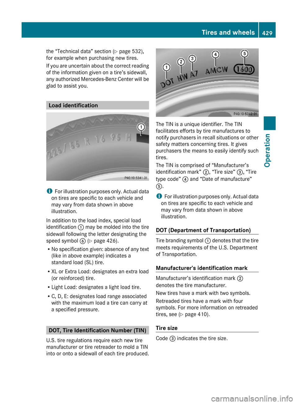
In addition to the load index, special load
identification : may be molded into the tire
sidewall following the letter designating the
speed symbol B (Y page 426).
RNo specification given: absence of any text
(like in above example) indicates a
standard load (SL) tire.
RXL or Extra Load: designates an extra load
(or reinforced) tire.
RLight Load: designates a light load tire.
RC, D, E: designates load range associated
with the maximum load a tire can carry at
a specified pressure.
DOT, Tire Identification Number (TIN)
U.S. tire regulations require each new tire
manufacturer or tire retreader to mold a TIN
into or onto a sidewall of each tire produced.
The TIN is a unique identifier. The TIN
facilitates efforts by tire manufactures to
notify purchasers in recall situations or other
safety matters concerning tires. It gives
purchasers the means to easily identify such
tires.
The TIN is comprised of “Manufacturer’s
identification mark” ;, “Tire size” =, “Tire
type code” ? and “Date of manufacture”
A.
iFor illustration purposes only. Actual data
on tires are specific to each vehicle and
may vary from data shown in above
illustration.
DOT (Department of Transportation)
Tire branding symbol : denotes that the tire
meets requirements of the U.S. Department
of Transportation.
Manufacturer’s identification mark
Manufacturer’s identification mark ;
denotes the tire manufacturer.
New tires have a mark with two symbols.
Retreaded tires have a mark with four
symbols. For more information on retreaded
tires, see (Y page 410).
Tire size
Code = indicates the tire size.
Tires and wheels429Operation221_AKB; 6; 20, en-USd2ugruen,Version: 2.11.8.12009-09-24T13:28:17+02:00 - Seite 429Z
Page 434 of 548
Sidewall
The portion of a tire between the tread and
the bead.
TIN (Tire Identification Number)
Unique identifier which facilitates efforts by
tire manufacturers to notify purchasers in
recall situations or other safety matters
concerning tires and gives purchasers the
means to easily identify such tires. The TIN is
comprised of “Manufacturer’s identification
mark”, “Tire size”, “Tire type code” and “Date
of manufacture”.
Tire ply composition and material used
This indicates the number of plies or the
number of layers of rubber-coated fabric in
the tire tread and sidewall. Tire
manufacturers also must indicate the ply
materials in the tire and sidewall, which
include steel, nylon, polyester, and others.
Tire speed rating
Part of tire designation (speed symbol);
indicates the speed range for which a tire is
approved.
Total load limit
Rated cargo and luggage load plus
68 kilograms (150 lb) times the vehicle’s
designated seating capacity.
Traction
The adhesive friction of a tire on a surface on
which it moves. The amount of grip provided.
Tread
The portion of a tire that comes into contact
with the road.
Treadwear indicators
Narrow bands, sometimes called “wear bars”
that show across the tread of a tire when only
1 / 16 in (1.6 mm) of tread remains.
Uniform Tire Quality Grading Standards
A tire information system that provides
consumers with ratings for a tire’s traction,
temperature and treadwear. Ratings are
determined by tire manufacturers using U.S.
government testing procedures. The ratings
are molded into the sidewall of the tire.
Vehicle maximum load on the tire
Load on an individual tire that is determined
by distributing to each axle its share of the
maximum loaded vehicle weight and dividing
it by two.
Winter driving
General information
Have your vehicle winterized at an authorized
Mercedes-Benz Center.
Winter tires
GWarning!
Winter tires with a tread depth of less than
1 / 6 in (4 mm) must be replaced. They are no
longer suitable for winter operation.
GWarning!
If you use your spare wheel when winter tires
are fitted on the other wheels, be aware that
the difference in tire characteristics may very
well impair turning stability and that overall
driving stability may be reduced. Adapt your
driving style accordingly.
Have the spare wheel replaced by a regular
road wheel with a winter tire at the nearest
authorized Mercedes-Benz Center.
432Winter drivingOperation
221_AKB; 6; 20, en-USd2ugruen,Version: 2.11.8.12009-09-24T13:28:17+02:00 - Seite 432
Page 435 of 548

Always use winter tires at temperatures
below 45‡ (7†) and whenever wintry road
conditions prevail. Not all M+S rated tires
provide special winter performance. Make
sure the tires you use show the mountain/
snowflake imarking on the tire sidewall.
These tires meet specific snow traction
performance requirements of the Rubber
Manufacturers Association (RMA) and the
Rubber Association of Canada (RAC) and
have been designed specifically for use in
snow conditions. Use of winter tires is the
only way to achieve the maximum
effectiveness of your vehicle’s driving safety
systems such as the ABS and the ESC in
winter operation.
For safe handling, make sure all mounted
winter tires are of the same make and have
the same tread design.
For information on winter tires for your
vehicle model, see the “Technical data”
section ( Y page 532).
Always observe the speed rating of the winter
tires installed on your vehicle.
After installing winter tires:XCheck the tire inflation pressure and adjust
it if necessary ( Y page 413).XRestart the Advanced Tire Pressure
Monitoring System ( Y page 414).
Snow chains
! When driving with snow chains, always
select the raised level of the vehicle level
control. Other settings may result in
damage to your vehicle.
! Some tire sizes do not leave adequate
clearance for snow chains. To help avoid
serious damage to your vehicle or tires,
make sure the use of snow chains is
permissible as specified in the “Technical
data” section of this Operator’s Manual.
Snow chains should only be driven on snow-
covered roads at speeds not to exceed
30 mph (50 km/h). Remove chains as soon
as possible when driving on roads without
snow.
Observe the following guidelines when using
snow chains:
R Use of snow chains is not permissible with
all wheel/tire combinations ( Y page 532).
R Use snow chains in pairs and on rear
wheels only. Follow the manufacturer’s
mounting instructions.
! If snow chains are mounted to the front
wheels, they may scrape against the body
or axle components. The tires or the vehicle
could be damaged as a result.
R Only use snow chains that are approved by
Mercedes-Benz. Any authorized Mercedes-
Benz Center will be glad to advise you on
this subject.
R Use of snow chains may be prohibited
depending on location. Always check local
and state laws before installing snow
chains.
R Do not use snow chains on the spare wheel.
i When driving with snow chains, you may
wish to switch off the ESC ( Y page 232)
before setting the vehicle in motion. This
will improve the vehicle’s traction.
Winter driving instructions
GWarning!
If the vehicle becomes stuck in snow, make
sure snow is kept clear of the exhaust pipe
and from around the vehicle with the engine
running. Otherwise, deadly carbon monoxide
(CO) gases may enter vehicle interior
resulting in unconsciousness and death.
To assure sufficient fresh air ventilation, open
a window slightly on the side of the vehicle
not facing the wind.
Winter driving433Operation221_AKB; 6; 20, en-USd2ugruen,Version: 2.11.8.12009-09-24T13:28:17+02:00 - Seite 433Z
Page 511 of 548
Open doors only when conditions are safe
to do so.XVehicles with KEYLESS-GO: Remove the
KEYLESS-GO start/stop button from the
starter switch.XHave any passenger exit the vehicle at a
safe distance from the roadway. Open
doors only when conditions are safe to do
so.
Mounting the spare wheel
Introduction
XPrepare the vehicle as described
( Y page 508).XTake the following out of the vehicle:
R spare wheel
R jack
R vehicle tool kit
For information on where to find the
respective items, see “Where will I find ...?”
( Y page 450) and ( Y page 451).
i Vehicles without spare wheel are not
factory-equipped with the tools required for
a wheel change such as a jack or a wheel
wrench. Some tools required for a wheel
change are specific to your vehicle.
Contact an authorized Mercedes-Benz
Center to obtain the tools approved for
your vehicle. This section describes the
wheel change using the tools approved and
recommended for your vehicle.
Lifting the vehicle
GWarning!
When jacking up the vehicle, only use the jack
which has been specifically approved by
Mercedes-Benz for your vehicle.
The jack is designed exclusively for jacking up
the vehicle at the jack take-up brackets built
into both sides of the vehicle. Make sure the
jack arm is fully seated in the jack take-up
bracket. The jack must always be vertical
when in use, especially on inclines or
declines.
The jack is intended only for lifting the vehicle
briefly for wheel changes. It is not suited for
performing maintenance work under the
vehicle. To help avoid personal injury, use the
jack only to lift the vehicle during a wheel
change.
Never get beneath the vehicle while it is
supported by the jack. Keep hands and feet
away from the area under the lifted vehicle.
Always lower the vehicle onto sufficient
capacity jackstands before working under the
vehicle.
Always make sure the electronic parking
brake is engaged. In addition, block the
wheels with wheel chocks or other sizeable
objects before raising the vehicle with the
jack. Do not disengage the electronic parking
brake while the vehicle is raised.
Make sure that the ground on which the
vehicle is standing and where you place the
jack is solid, level and not slippery. If
necessary, use a large underlay. On slippery
surfaces, such as tiled floors, you should use
a non-slip underlay, for example a rubber mat.
Do not use wooden blocks or similar objects
to support the jack. Otherwise the jack may
not be able to achieve its load-bearing
capacity if it is not at its full height.
Never start the engine when the vehicle is
raised.
Also observe the notes on the jack.XPrevent the vehicle from rolling away by
blocking wheels with wheel chocks or other
sizeable objects.
When your vehicle is equipped with a wheel
chock, it is included with the vehicle tool kit
( Y page 450). For information on setting up
the collapsible wheel chock, see
( Y page 450).Flat tire509Practical hints221_AKB; 6; 20, en-USd2ugruen,Version: 2.11.8.12009-09-24T13:28:17+02:00 - Seite 509Z
Page 512 of 548
When changing a wheel on a level surface:XPlace a wheel chock or other sizeable
object in front of and another wheel chock
or other sizeable object behind the wheel
that is diagonally opposite to the wheel
being changed.
Always try lifting the vehicle using the jack on
a level surface. However, should
circumstances require you to do so on a hill:
XPlace wheel chocks or other sizeable
objects on the downhill side in front of both
wheels on the side opposite to the side on
which the wheel is to be changed.
GWarning!
Only jack up the vehicle on level ground or on
slight inclines/declines. Otherwise, the
vehicle could fall off the jack and injure you or
others.
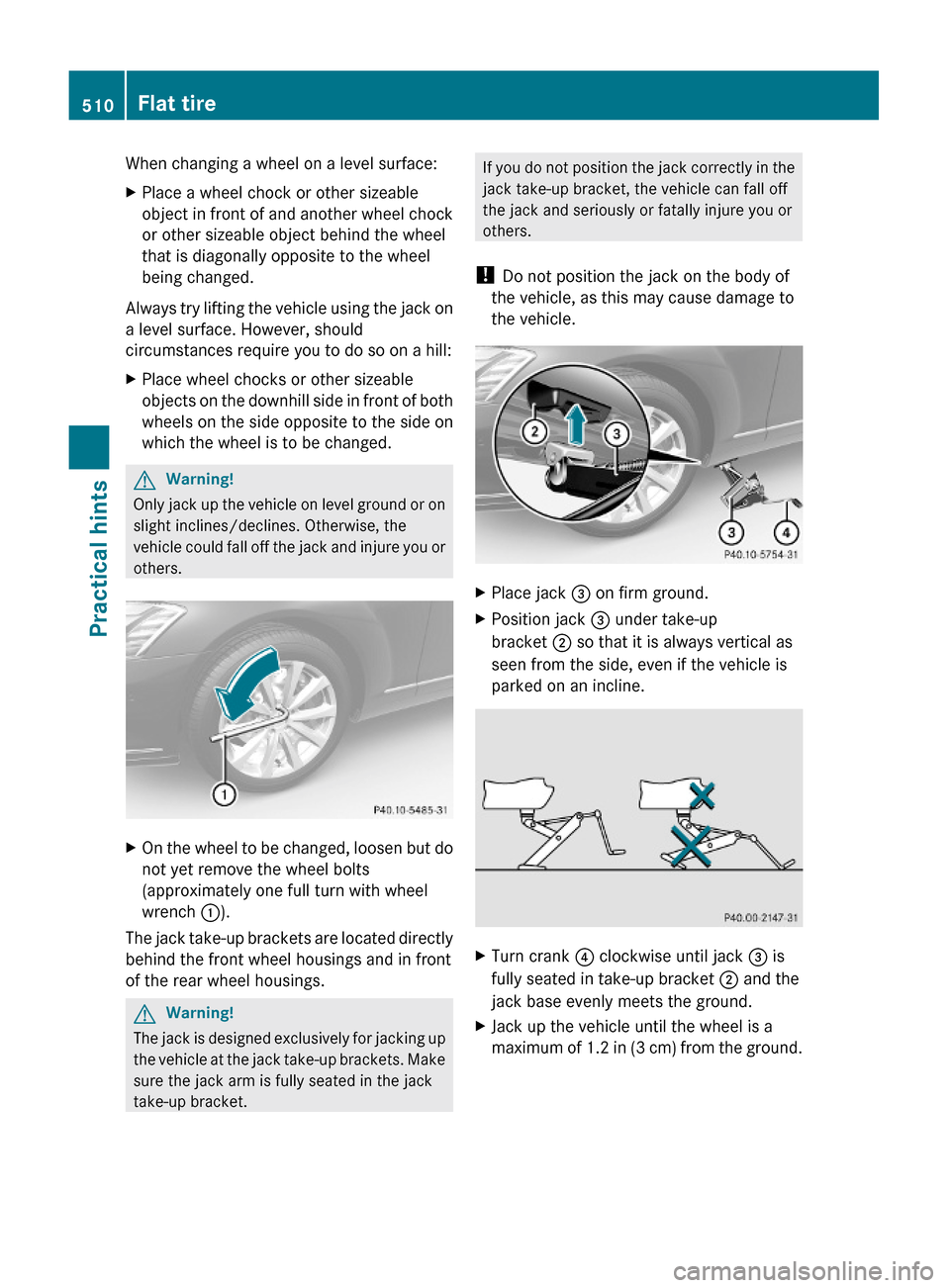
XOn the wheel to be changed, loosen but do
not yet remove the wheel bolts
(approximately one full turn with wheel
wrench :).
The jack take-up brackets are located directly
behind the front wheel housings and in front
of the rear wheel housings.
GWarning!
The jack is designed exclusively for jacking up
the vehicle at the jack take-up brackets. Make
sure the jack arm is fully seated in the jack
take-up bracket.
If you do not position the jack correctly in the
jack take-up bracket, the vehicle can fall off
the jack and seriously or fatally injure you or
others.
! Do not position the jack on the body of
the vehicle, as this may cause damage to
the vehicle.
XPlace jack = on firm ground.XPosition jack = under take-up
bracket ; so that it is always vertical as
seen from the side, even if the vehicle is
parked on an incline.
XTurn crank ? clockwise until jack = is
fully seated in take-up bracket ; and the
jack base evenly meets the ground.
XJack up the vehicle until the wheel is a
maximum of 1.2 in (3 cm) from the ground.
510Flat tirePractical hints
221_AKB; 6; 20, en-USd2ugruen,Version: 2.11.8.12009-09-24T13:28:17+02:00 - Seite 510
Page 514 of 548
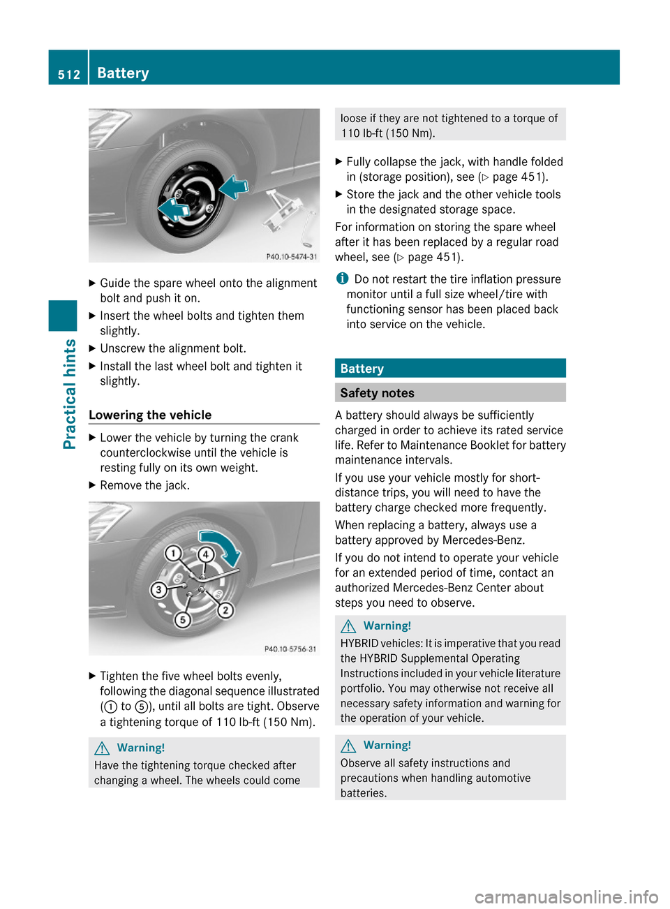
XGuide the spare wheel onto the alignment
bolt and push it on.
XInsert the wheel bolts and tighten them
slightly.
XUnscrew the alignment bolt.XInstall the last wheel bolt and tighten it
slightly.
Lowering the vehicle
XLower the vehicle by turning the crank
counterclockwise until the vehicle is
resting fully on its own weight.
XRemove the jack.XTighten the five wheel bolts evenly,
following the diagonal sequence illustrated
(: to A), until all bolts are tight. Observe
a tightening torque of 110 lb-ft (150 Nm).
GWarning!
Have the tightening torque checked after
changing a wheel. The wheels could come
loose if they are not tightened to a torque of
110 lb-ft (150 Nm).
XFully collapse the jack, with handle folded
in (storage position), see (Y page 451).
XStore the jack and the other vehicle tools
in the designated storage space.
For information on storing the spare wheel
after it has been replaced by a regular road
wheel, see (Y page 451).
iDo not restart the tire inflation pressure
monitor until a full size wheel/tire with
functioning sensor has been placed back
into service on the vehicle.
Battery
Safety notes
A battery should always be sufficiently
charged in order to achieve its rated service
life. Refer to Maintenance Booklet for battery
maintenance intervals.
If you use your vehicle mostly for short-
distance trips, you will need to have the
battery charge checked more frequently.
When replacing a battery, always use a
battery approved by Mercedes-Benz.
If you do not intend to operate your vehicle
for an extended period of time, contact an
authorized Mercedes-Benz Center about
steps you need to observe.
GWarning!
HYBRID vehicles: It is imperative that you read
the HYBRID Supplemental Operating
Instructions included in your vehicle literature
portfolio. You may otherwise not receive all
necessary safety information and warning for
the operation of your vehicle.
GWarning!
Observe all safety instructions and
precautions when handling automotive
batteries.
512BatteryPractical hints
221_AKB; 6; 20, en-USd2ugruen,Version: 2.11.8.12009-09-24T13:28:17+02:00 - Seite 512