2010 MERCEDES-BENZ S65AMG width
[x] Cancel search: widthPage 53 of 548
around a person and another person or
other objects at the same time.
RSeat belts should not be worn twisted. In a
crash, you would not have the full width of
the seat belt to distribute impact forces.
The twisted seat belt against your body
could cause injuries.
RPregnant women should also always use a
lap/shoulder belt. The lap belt portion
should be positioned as low as possible on
the hips to avoid any possible pressure on
the abdomen.
RPlace the seat backrest in a position that is
as upright as possible.
RCheck your seat belt during travel to make
sure it is properly positioned.
RNever place your feet on the instrument
panel, dashboard, or on the seat. Always
keep both feet on the floor in front of the
seat.
RWhen using a seat belt to secure infant
restraints, toddler restraints, or children in
booster seats, always follow the child seat
manufacturer’s instructions.
GWarning!
Do not pass seat belts over sharp edges. They
could tear.
Do not allow the seat belt to get caught in the
door or in the seat adjustment mechanism.
This could damage the seat belt.
Never attempt to make modifications to seat
belts. This could impair the effectiveness of
the seat belts.
Fastening the seat belts
GWarning!
According to accident statistics, children are
safer when properly restrained in the rear
seating positions than in the front seating
position. Thus, we strongly recommend that
children be placed in the rear seats whenever
possible. Regardless of seating position,
children 12 years old and under must be
seated and properly secured in an
appropriately sized infant restraint, toddler
restraint, or booster seat recommended for
the size and weight of the child. For additional
information, see “Children in the vehicle”.
A child’s risk of serious or fatal injuries is
significantly increased if the child restraints
are not properly secured in the vehicle and/
or the child is not properly secured in the child
restraint.
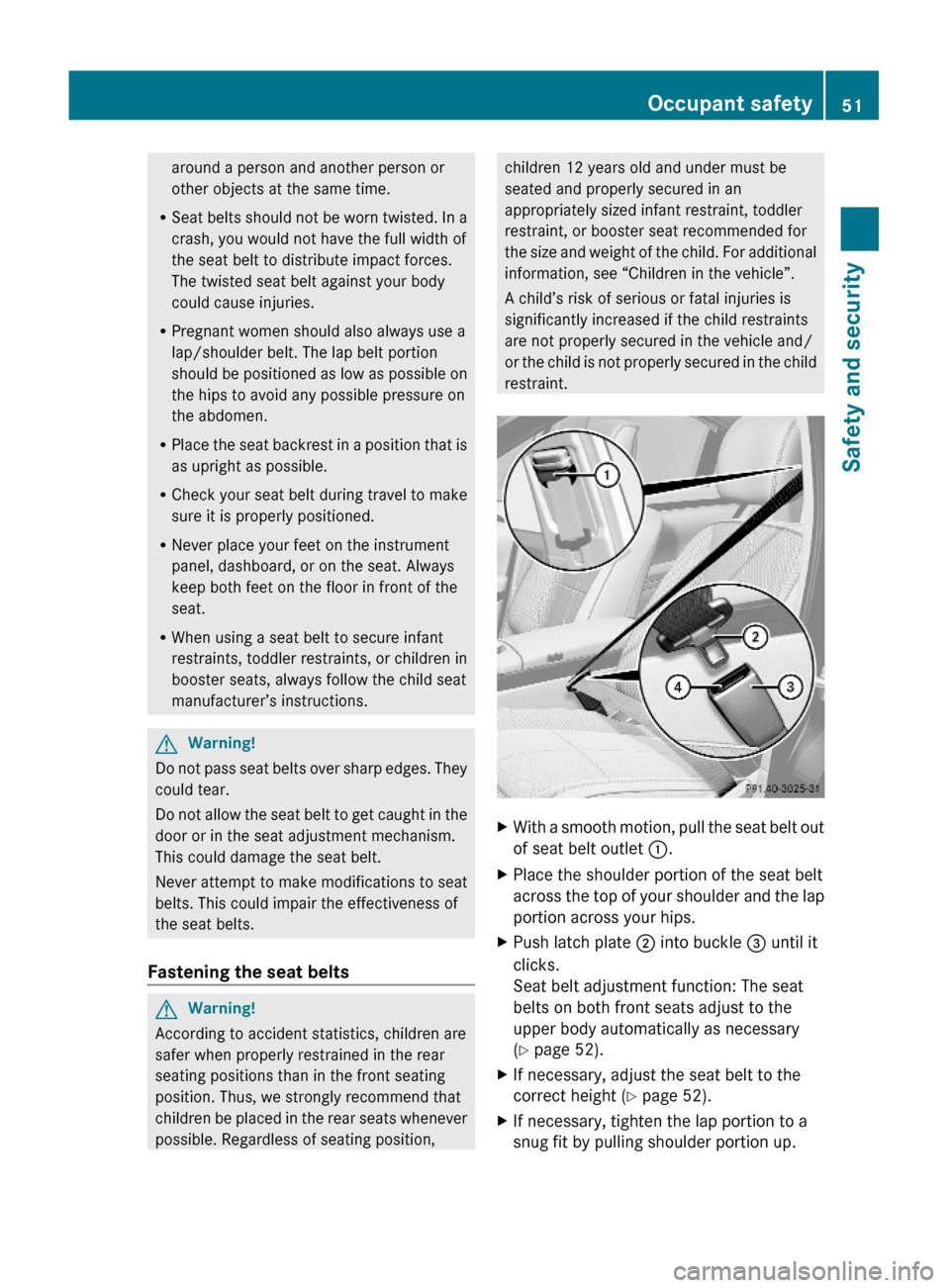
XWith a smooth motion, pull the seat belt out
of seat belt outlet :.
XPlace the shoulder portion of the seat belt
across the top of your shoulder and the lap
portion across your hips.
XPush latch plate ; into buckle = until it
clicks.
Seat belt adjustment function: The seat
belts on both front seats adjust to the
upper body automatically as necessary
(Y page 52).
XIf necessary, adjust the seat belt to the
correct height (Y page 52).
XIf necessary, tighten the lap portion to a
snug fit by pulling shoulder portion up.
Occupant safety51Safety and security221_AKB; 6; 20, en-USd2ugruen,Version: 2.11.8.12009-09-24T13:28:17+02:00 - Seite 51Z
Page 295 of 548
Multicontour seats, rear
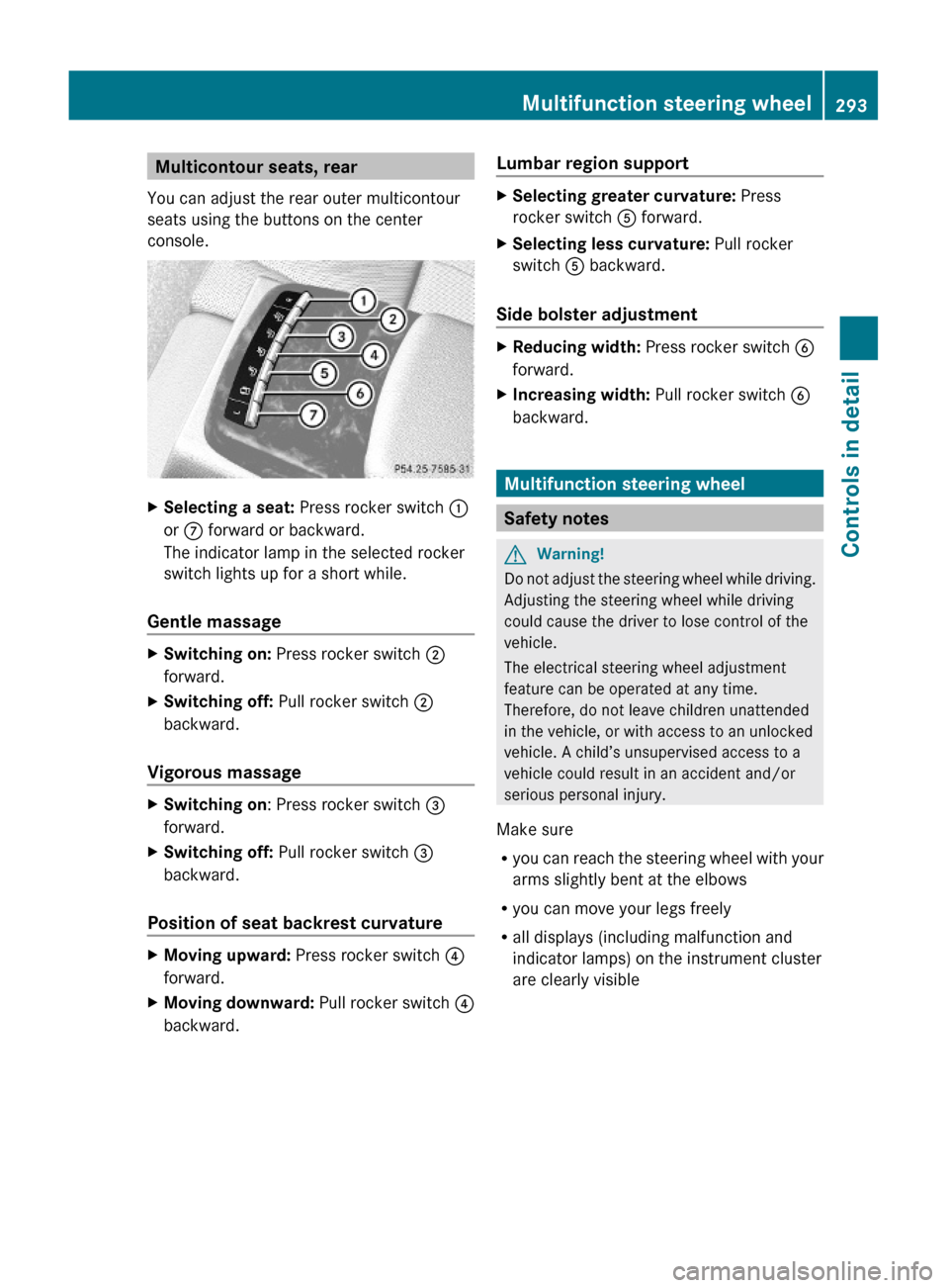
You can adjust the rear outer multicontour
seats using the buttons on the center
console.
XSelecting a seat: Press rocker switch :
or C forward or backward.
The indicator lamp in the selected rocker
switch lights up for a short while.
Gentle massage
XSwitching on: Press rocker switch ;
forward.
XSwitching off: Pull rocker switch ;
backward.
Vigorous massage
XSwitching on: Press rocker switch =
forward.
XSwitching off: Pull rocker switch =
backward.
Position of seat backrest curvature
XMoving upward: Press rocker switch ?
forward.
XMoving downward: Pull rocker switch ?
backward.
Lumbar region supportXSelecting greater curvature: Press
rocker switch A forward.
XSelecting less curvature: Pull rocker
switch A backward.
Side bolster adjustment
XReducing width: Press rocker switch B
forward.
XIncreasing width: Pull rocker switch B
backward.
Multifunction steering wheel
Safety notes
GWarning!
Do not adjust the steering wheel while driving.
Adjusting the steering wheel while driving
could cause the driver to lose control of the
vehicle.
The electrical steering wheel adjustment
feature can be operated at any time.
Therefore, do not leave children unattended
in the vehicle, or with access to an unlocked
vehicle. A child’s unsupervised access to a
vehicle could result in an accident and/or
serious personal injury.
Make sure
Ryou can reach the steering wheel with your
arms slightly bent at the elbows
Ryou can move your legs freely
Rall displays (including malfunction and
indicator lamps) on the instrument cluster
are clearly visible
Multifunction steering wheel293Controls in detail221_AKB; 6; 20, en-USd2ugruen,Version: 2.11.8.12009-09-24T13:28:17+02:00 - Seite 293Z
Page 357 of 548
GWarning!
Use of rear view camera can be dangerous if
you are color-blind or have impaired color
vision.
Only use rear view camera if you can see and
distinguish all colored guidelines shown by
rear view camera on the COMAND system
display.
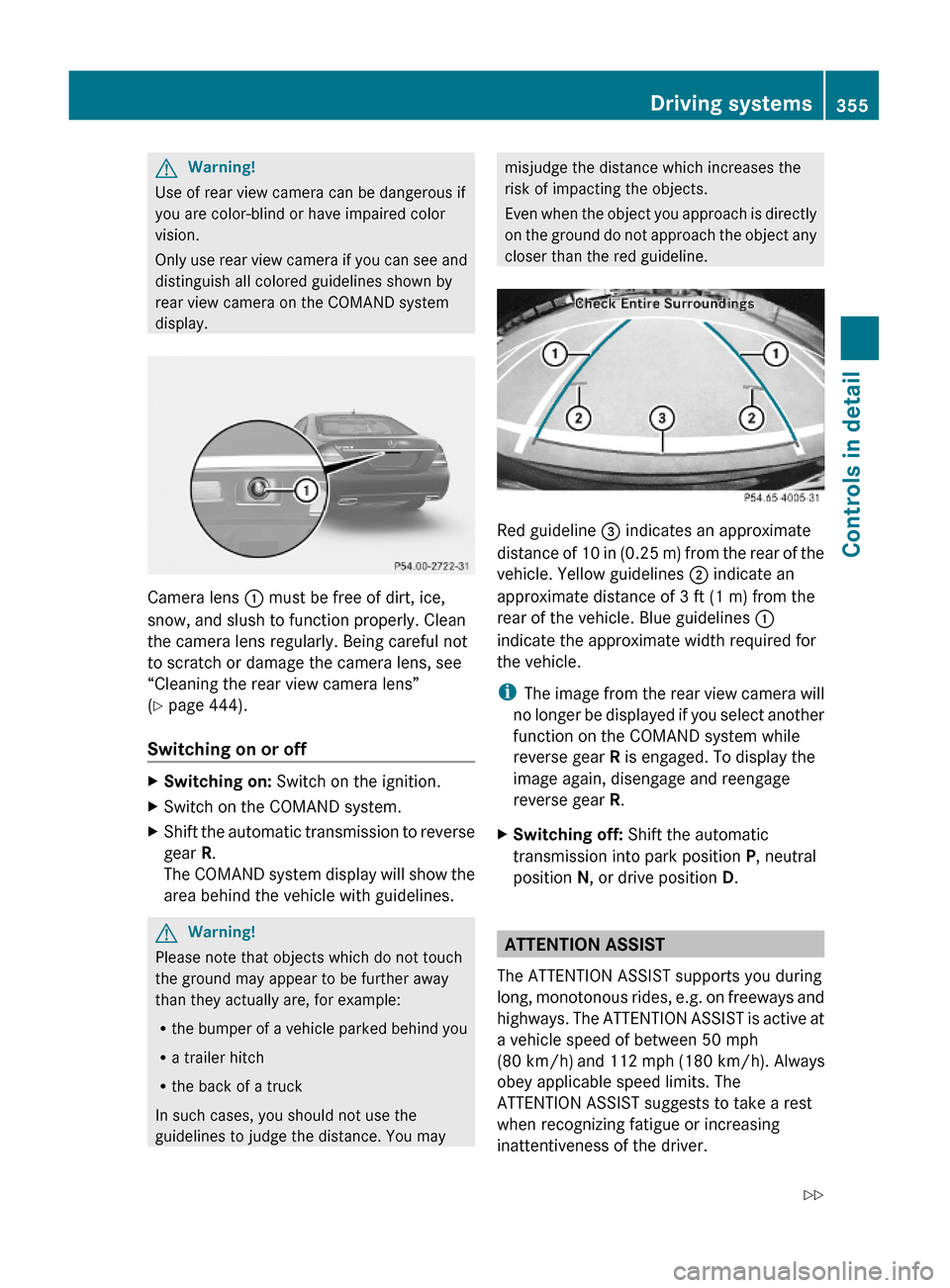
Camera lens : must be free of dirt, ice,
snow, and slush to function properly. Clean
the camera lens regularly. Being careful not
to scratch or damage the camera lens, see
“Cleaning the rear view camera lens”
(Y page 444).
Switching on or off
XSwitching on: Switch on the ignition.XSwitch on the COMAND system.XShift the automatic transmission to reverse
gear R.
The COMAND system display will show the
area behind the vehicle with guidelines.
GWarning!
Please note that objects which do not touch
the ground may appear to be further away
than they actually are, for example:
Rthe bumper of a vehicle parked behind you
Ra trailer hitch
Rthe back of a truck
In such cases, you should not use the
guidelines to judge the distance. You may
misjudge the distance which increases the
risk of impacting the objects.
Even when the object you approach is directly
on the ground do not approach the object any
closer than the red guideline.
Red guideline = indicates an approximate
distance of 10 in (0.25 m) from the rear of the
vehicle. Yellow guidelines ; indicate an
approximate distance of 3 ft (1 m) from the
rear of the vehicle. Blue guidelines :
indicate the approximate width required for
the vehicle.
iThe image from the rear view camera will
no longer be displayed if you select another
function on the COMAND system while
reverse gear R is engaged. To display the
image again, disengage and reengage
reverse gear R.
XSwitching off: Shift the automatic
transmission into park position P, neutral
position N, or drive position D.
ATTENTION ASSIST
The ATTENTION ASSIST supports you during
long, monotonous rides, e.g. on freeways and
highways. The ATTENTION ASSIST is active at
a vehicle speed of between 50 mph
(80 km/h) and 112 mph (180 km/h). Always
obey applicable speed limits. The
ATTENTION ASSIST suggests to take a rest
when recognizing fatigue or increasing
inattentiveness of the driver.
Driving systems355Controls in detail221_AKB; 6; 20, en-USd2ugruen,Version: 2.11.8.12009-09-24T13:28:17+02:00 - Seite 355Z
Page 362 of 548
sensor is intended for use in an automotive
radar system only. Removal, tampering, or
altering of the device will void any
warranties, and is not permitted by the
FCC. Do not tamper with, alter, or use in
any non-approved way.
Any unauthorized modification to this
device could void the user’s authority to
operate the equipment.
iCanada only:
This device complies with RSS-210 of
Industry Canada. Operation is subject to
the following two conditions:
1.This device may not cause interference,
and
2. this device must accept any
interference received, including
interference that may cause undesired
operation of the device.
Removal, tampering, or altering of the
device will void any warranties, and is not
permitted. Do not tamper with, alter, or use
in any non-approved way.
Any unauthorized modification to this
device could void the user’s authority to
operate the equipment.
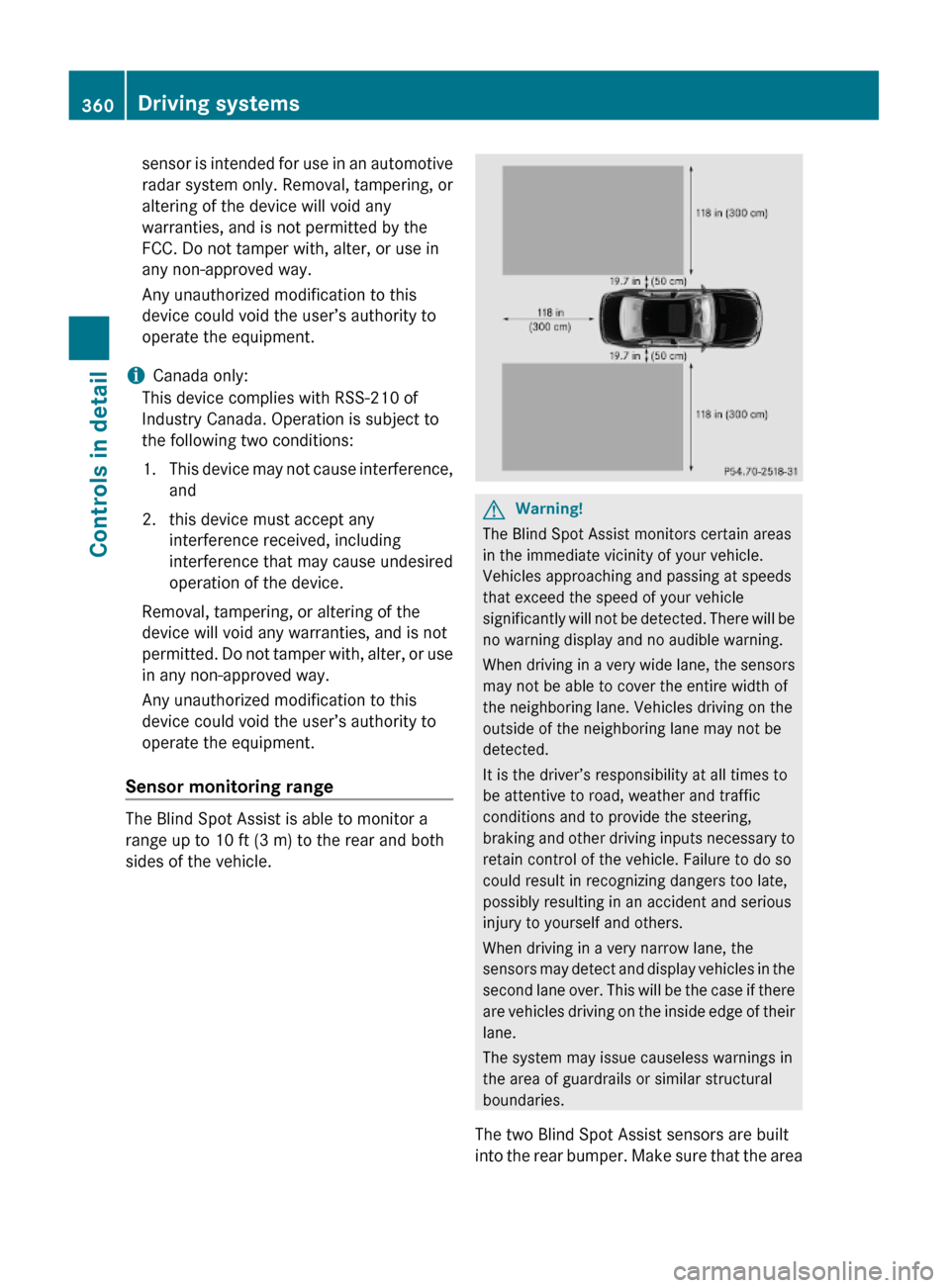
Sensor monitoring range
The Blind Spot Assist is able to monitor a
range up to 10 ft (3 m) to the rear and both
sides of the vehicle.
GWarning!
The Blind Spot Assist monitors certain areas
in the immediate vicinity of your vehicle.
Vehicles approaching and passing at speeds
that exceed the speed of your vehicle
significantly will not be detected. There will be
no warning display and no audible warning.
When driving in a very wide lane, the sensors
may not be able to cover the entire width of
the neighboring lane. Vehicles driving on the
outside of the neighboring lane may not be
detected.
It is the driver’s responsibility at all times to
be attentive to road, weather and traffic
conditions and to provide the steering,
braking and other driving inputs necessary to
retain control of the vehicle. Failure to do so
could result in recognizing dangers too late,
possibly resulting in an accident and serious
injury to yourself and others.
When driving in a very narrow lane, the
sensors may detect and display vehicles in the
second lane over. This will be the case if there
are vehicles driving on the inside edge of their
lane.
The system may issue causeless warnings in
the area of guardrails or similar structural
boundaries.
The two Blind Spot Assist sensors are built
into the rear bumper. Make sure that the area
360Driving systemsControls in detail
221_AKB; 6; 20, en-USd2ugruen,Version: 2.11.8.12009-09-24T13:28:17+02:00 - Seite 360
Page 426 of 548
Storing tires
! Keep unmounted tires in a cool, dry place
with as little exposure to light as possible.
Protect tires from contact with oil, grease
and fuels.
Cleaning tires
! Never use a round nozzle to power wash
tires. The intense jet of water can result in
damage to the tire.
Always replace a damaged tire.
Uniform Tire Quality Grading
Standards
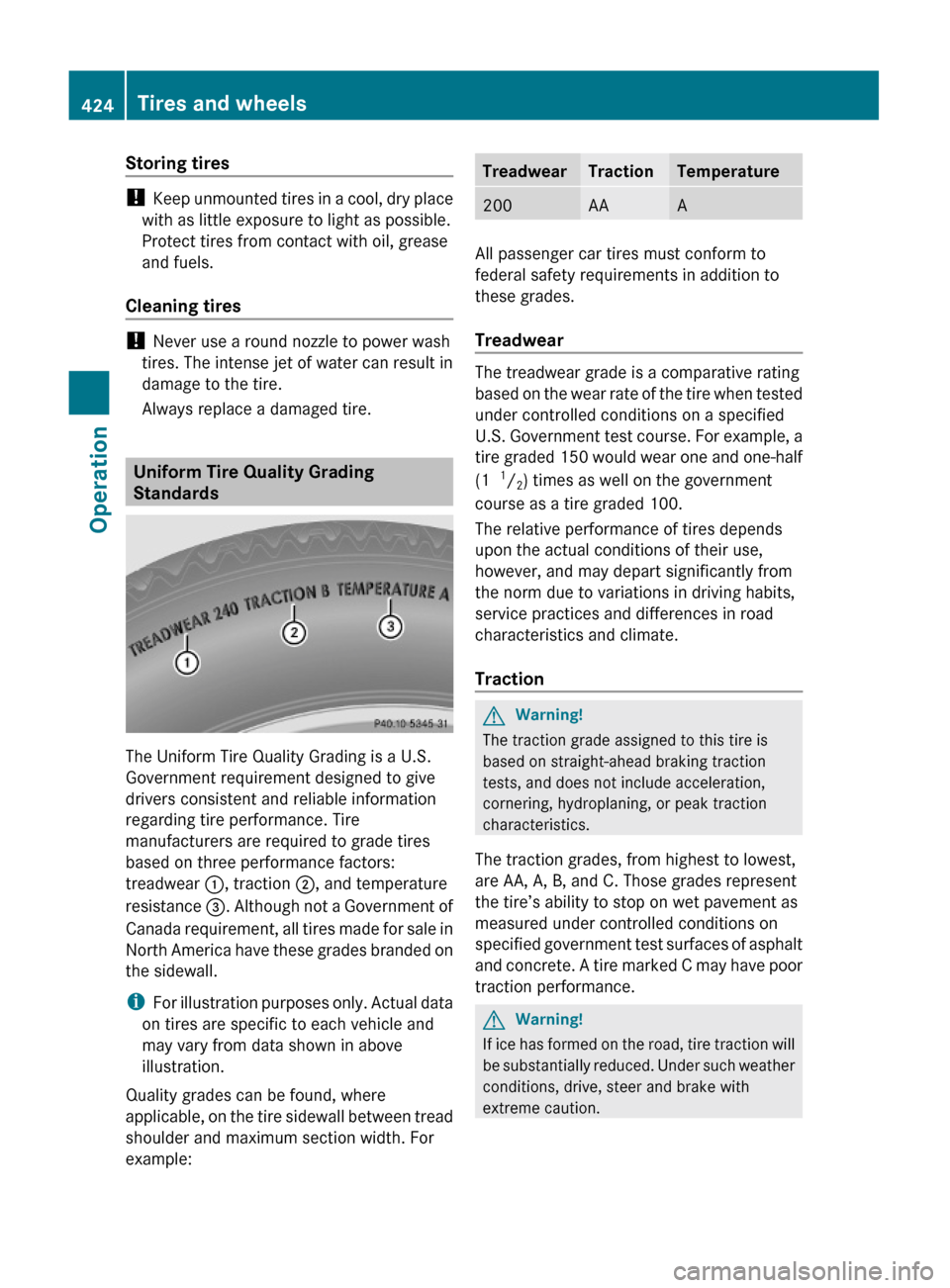
The Uniform Tire Quality Grading is a U.S.
Government requirement designed to give
drivers consistent and reliable information
regarding tire performance. Tire
manufacturers are required to grade tires
based on three performance factors:
treadwear :, traction ;, and temperature
resistance =. Although not a Government of
Canada requirement, all tires made for sale in
North America have these grades branded on
the sidewall.
iFor illustration purposes only. Actual data
on tires are specific to each vehicle and
may vary from data shown in above
illustration.
Quality grades can be found, where
applicable, on the tire sidewall between tread
shoulder and maximum section width. For
example:
TreadwearTractionTemperature200AAA
All passenger car tires must conform to
federal safety requirements in addition to
these grades.
Treadwear
The treadwear grade is a comparative rating
based on the wear rate of the tire when tested
under controlled conditions on a specified
U.S. Government test course. For example, a
tire graded 150 would wear one and one-half
(1 1/2) times as well on the government
course as a tire graded 100.
The relative performance of tires depends
upon the actual conditions of their use,
however, and may depart significantly from
the norm due to variations in driving habits,
service practices and differences in road
characteristics and climate.
Traction
GWarning!
The traction grade assigned to this tire is
based on straight-ahead braking traction
tests, and does not include acceleration,
cornering, hydroplaning, or peak traction
characteristics.
The traction grades, from highest to lowest,
are AA, A, B, and C. Those grades represent
the tire’s ability to stop on wet pavement as
measured under controlled conditions on
specified government test surfaces of asphalt
and concrete. A tire marked C may have poor
traction performance.
GWarning!
If ice has formed on the road, tire traction will
be substantially reduced. Under such weather
conditions, drive, steer and brake with
extreme caution.
424Tires and wheelsOperation
221_AKB; 6; 20, en-USd2ugruen,Version: 2.11.8.12009-09-24T13:28:17+02:00 - Seite 424
Page 428 of 548
Thoroughly clean the mounting face of wheels
and brake disks, i.e. the inner side of the
wheels/tires, during each rotation. Check for
and ensure proper tire inflation pressure.
For information on wheel change, see “Flat
tire” (Y page 508).
Tire labeling
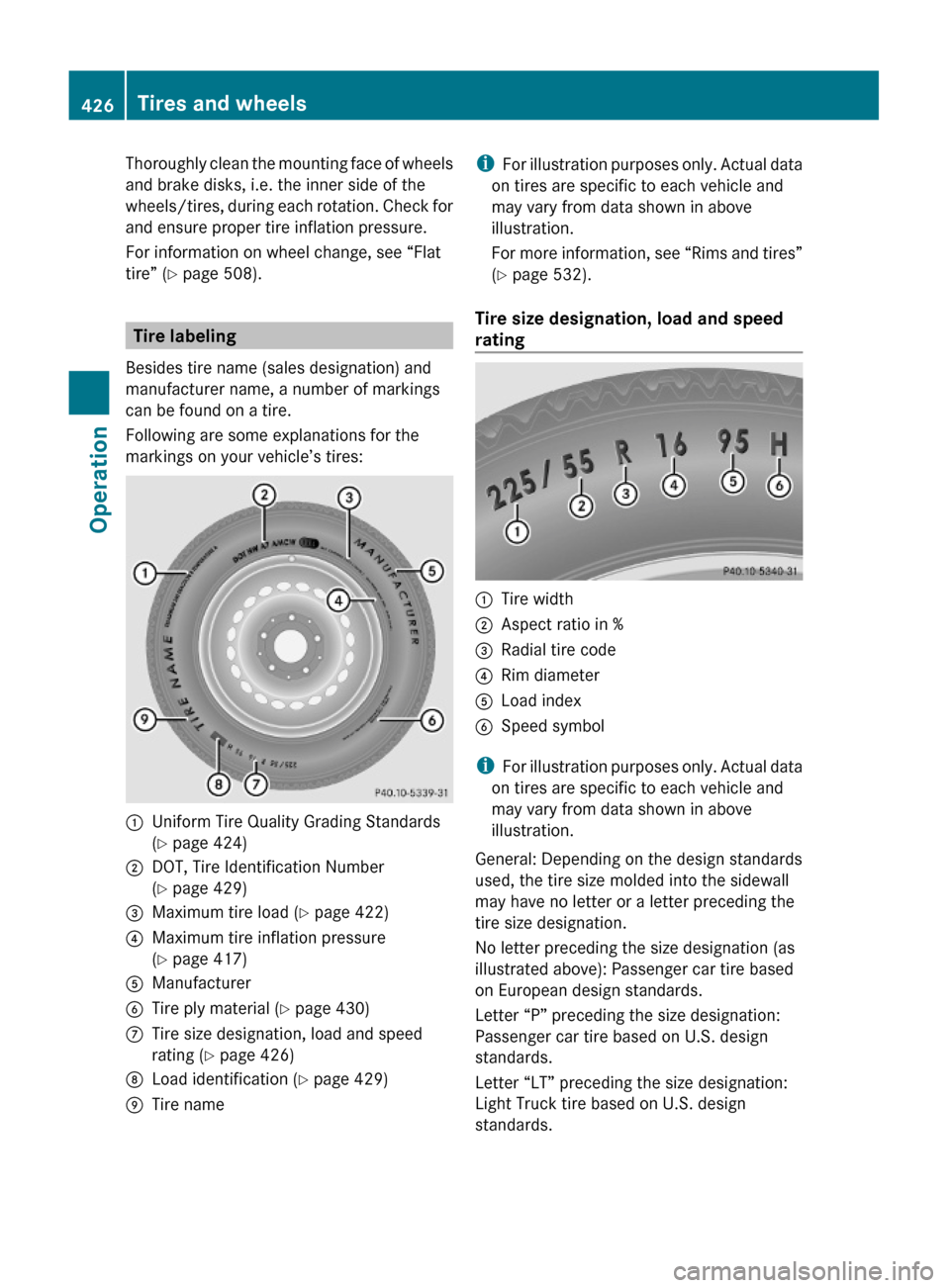
Besides tire name (sales designation) and
manufacturer name, a number of markings
can be found on a tire.
Following are some explanations for the
markings on your vehicle’s tires:
:Uniform Tire Quality Grading Standards
(Y page 424)
;DOT, Tire Identification Number
(Y page 429)
=Maximum tire load (Y page 422)?Maximum tire inflation pressure
(Y page 417)
AManufacturerBTire ply material (Y page 430)CTire size designation, load and speed
rating (Y page 426)
DLoad identification (Y page 429)ETire nameiFor illustration purposes only. Actual data
on tires are specific to each vehicle and
may vary from data shown in above
illustration.
For more information, see “Rims and tires”
(Y page 532).
Tire size designation, load and speed
rating
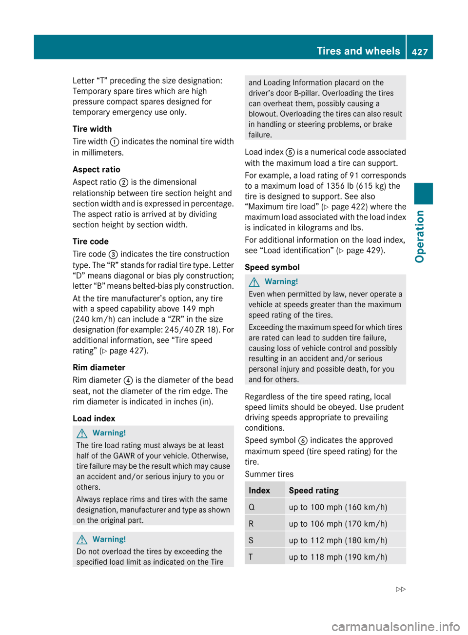
:Tire width;Aspect ratio in %=Radial tire code?Rim diameterALoad index BSpeed symbol
iFor illustration purposes only. Actual data
on tires are specific to each vehicle and
may vary from data shown in above
illustration.
General: Depending on the design standards
used, the tire size molded into the sidewall
may have no letter or a letter preceding the
tire size designation.
No letter preceding the size designation (as
illustrated above): Passenger car tire based
on European design standards.
Letter “P” preceding the size designation:
Passenger car tire based on U.S. design
standards.
Letter “LT” preceding the size designation:
Light Truck tire based on U.S. design
standards.
426Tires and wheelsOperation
221_AKB; 6; 20, en-USd2ugruen,Version: 2.11.8.12009-09-24T13:28:17+02:00 - Seite 426
Page 429 of 548
Letter “T” preceding the size designation:
Temporary spare tires which are high
pressure compact spares designed for
temporary emergency use only.
Tire width
Tire width : indicates the nominal tire width
in millimeters.
Aspect ratio
Aspect ratio ; is the dimensional
relationship between tire section height and
section width and is expressed in percentage.
The aspect ratio is arrived at by dividing
section height by section width.
Tire code
Tire code = indicates the tire construction
type. The “R” stands for radial tire type. Letter
“D” means diagonal or bias ply construction;
letter “B” means belted-bias ply construction.
At the tire manufacturer’s option, any tire
with a speed capability above 149 mph
(240 km/h) can include a “ZR” in the size
designation (for example: 245/40 ZR 18). For
additional information, see “Tire speed
rating” ( Y page 427).
Rim diameter
Rim diameter ? is the diameter of the bead
seat, not the diameter of the rim edge. The
rim diameter is indicated in inches (in).
Load indexGWarning!
The tire load rating must always be at least
half of the GAWR of your vehicle. Otherwise,
tire failure may be the result which may cause
an accident and/or serious injury to you or
others.
Always replace rims and tires with the same
designation, manufacturer and type as shown
on the original part.
GWarning!
Do not overload the tires by exceeding the
specified load limit as indicated on the Tire
and Loading Information placard on the
driver’s door B-pillar. Overloading the tires
can overheat them, possibly causing a
blowout. Overloading the tires can also result
in handling or steering problems, or brake
failure.
Load index A is a numerical code associated
with the maximum load a tire can support.
For example, a load rating of 91 corresponds
to a maximum load of 1356 lb (615 kg) the
tire is designed to support. See also
“Maximum tire load” (Y page 422) where the
maximum load associated with the load index
is indicated in kilograms and lbs.
For additional information on the load index,
see “Load identification” ( Y page 429).
Speed symbol GWarning!
Even when permitted by law, never operate a
vehicle at speeds greater than the maximum
speed rating of the tires.
Exceeding the maximum speed for which tires
are rated can lead to sudden tire failure,
causing loss of vehicle control and possibly
resulting in an accident and/or serious
personal injury and possible death, for you
and for others.
Regardless of the tire speed rating, local
speed limits should be obeyed. Use prudent
driving speeds appropriate to prevailing
conditions.
Speed symbol B indicates the approved
maximum speed (tire speed rating) for the
tire.
Summer tires
IndexSpeed ratingQup to 100 mph (160 km/h)Rup to 106 mph (170 km/h)Sup to 112 mph (180 km/h)Tup to 118 mph (190 km/h)Tires and wheels427Operation221_AKB; 6; 20, en-USd2ugruen,Version: 2.11.8.12009-09-24T13:28:17+02:00 - Seite 427Z
Page 432 of 548
Tire type code
Tire type code ? may, at the option of the
manufacturer, be used as a descriptive code
for identifying significant characteristics of
the tire.
Date of manufacture
The date of manufacture A identifies the
week and year of manufacture.
The first two figures identify the week,
starting with “01” to represent the first full
week of the calendar year. The second two
figures represent the year.
For example, “3208” represents the 32nd
week of 2008.
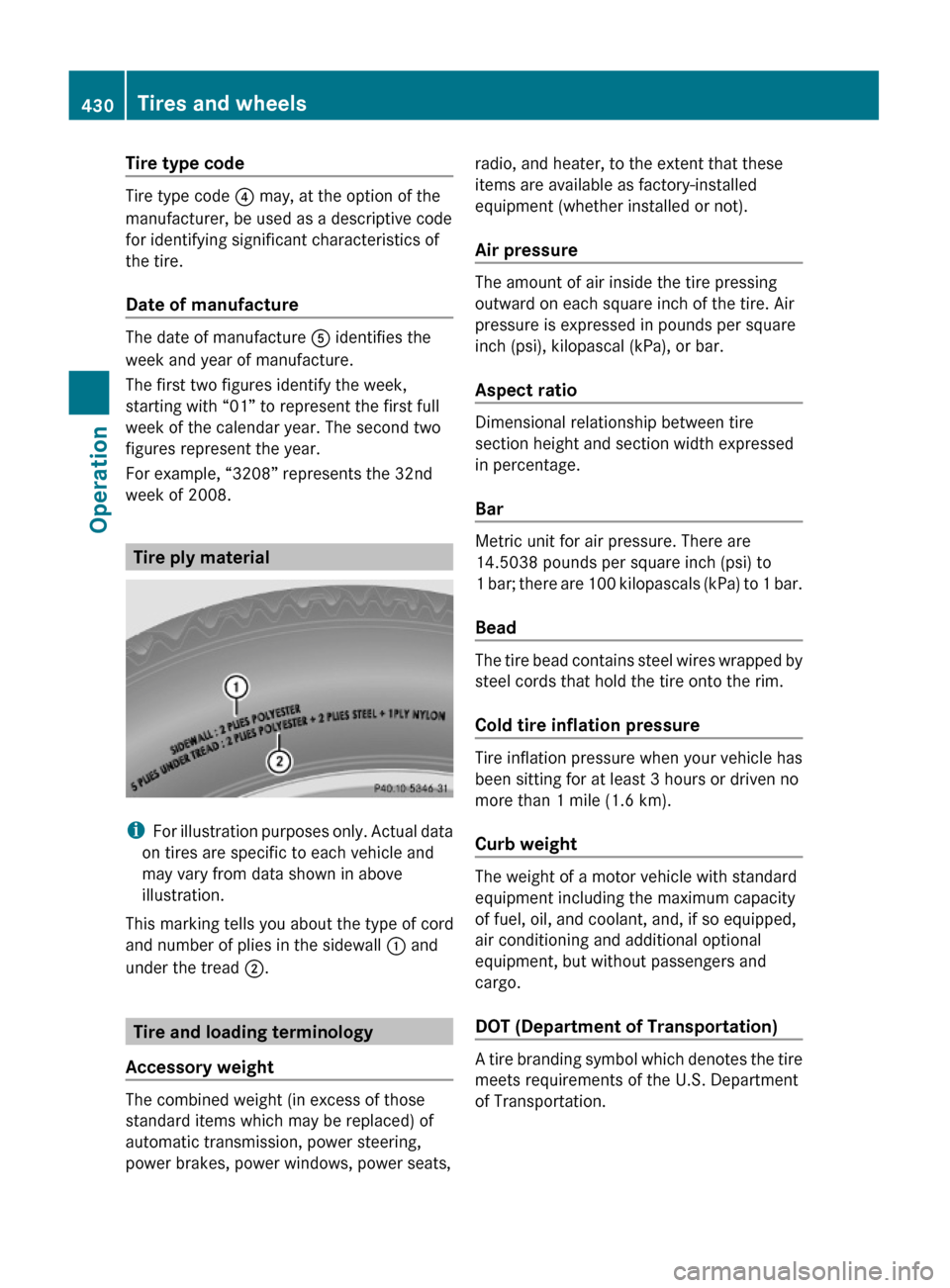
Tire ply material
iFor illustration purposes only. Actual data
on tires are specific to each vehicle and
may vary from data shown in above
illustration.
This marking tells you about the type of cord
and number of plies in the sidewall : and
under the tread ;.
Tire and loading terminology
Accessory weight
The combined weight (in excess of those
standard items which may be replaced) of
automatic transmission, power steering,
power brakes, power windows, power seats,
radio, and heater, to the extent that these
items are available as factory-installed
equipment (whether installed or not).
Air pressure
The amount of air inside the tire pressing
outward on each square inch of the tire. Air
pressure is expressed in pounds per square
inch (psi), kilopascal (kPa), or bar.
Aspect ratio
Dimensional relationship between tire
section height and section width expressed
in percentage.
Bar
Metric unit for air pressure. There are
14.5038 pounds per square inch (psi) to
1 bar; there are 100 kilopascals (kPa) to 1 bar.
Bead
The tire bead contains steel wires wrapped by
steel cords that hold the tire onto the rim.
Cold tire inflation pressure
Tire inflation pressure when your vehicle has
been sitting for at least 3 hours or driven no
more than 1 mile (1.6 km).
Curb weight
The weight of a motor vehicle with standard
equipment including the maximum capacity
of fuel, oil, and coolant, and, if so equipped,
air conditioning and additional optional
equipment, but without passengers and
cargo.
DOT (Department of Transportation)
A tire branding symbol which denotes the tire
meets requirements of the U.S. Department
of Transportation.
430Tires and wheelsOperation
221_AKB; 6; 20, en-USd2ugruen,Version: 2.11.8.12009-09-24T13:28:17+02:00 - Seite 430