2010 MERCEDES-BENZ R320 spare wheel
[x] Cancel search: spare wheelPage 254 of 364
Snow chains
! Vehicles with Adaptive Damping System
(ADS):
When driving with snow chains, do not
select SPORT mode as this may result in
damage to your vehicle.
! Some tire sizes do not leave adequate
clearance for snow chains. To help avoid
serious damage to your vehicle or tires,
make sure the use of snow chains is
permissible as specified in the “Technical
data” section of this Operator’s Manual.
Snow chains should only be driven on snow-
covered roads at speeds not to exceed
30 mph (50 km/h)
. Remove chains as soon
as possible when driving on roads without
snow.
Observe the following guidelines when using
snow chains:
R Use of snow chains is not permissible with
all wheel/tire combinations ( Y page 347).
R Use snow chains in pairs and on rear
wheels only. Follow the manufacturer’s
mounting instructions.
! If snow chains are mounted to the front
wheels, they may scrape against the body
or axle components. The tires or the vehicle
could be damaged as a result.
R Only use snow chains that are approved by
Mercedes-Benz. Any authorized Mercedes-
Benz Center will be glad to advise you on
this subject.
R Use of snow chains may be prohibited
depending on location. Always check local
and state laws before installing snow
chains.
R Do not use snow chains on the spare wheel.
i When driving with snow chains, you may
wish to switch off the ESP ®
(Y page 65)
before setting the vehicle in motion. This
will improve the vehicle’s traction. Winter driving instructions
G
Warning!
If the vehicle becomes stuck in snow, make
sure snow is kept clear of the exhaust pipe
and from around the vehicle with the engine
running. Otherwise, deadly carbon monoxide
(CO) gases may enter vehicle interior
resulting in unconsciousness and death.
To
assure sufficient fresh air ventilation, open
a window slightly on the side of the vehicle
not facing the wind. G
Warning!
The outside temperature indicator is not
designed to serve as an ice-warning device
and is therefore unsuitable for that purpose.
Indicated temperatures just above the
freezing
point do not guarantee that the road
surface is free of ice. The road may still be icy,
especially in wooded areas or on bridges. G
Warning!
On slippery road surfaces, never downshift in
order to obtain braking action. This could
result
in drive wheel slip and reduced vehicle
control. Your vehicle’s ABS will not prevent
this type of loss of control.
The most important rule for slippery or icy
roads is to drive sensibly and to avoid abrupt
acceleration, braking and steering
maneuvers. Do not use the cruise control
system under such conditions.
When the vehicle is in danger of skidding, shift
the automatic transmission to neutral
position N. Try to keep the vehicle under
control by corrective steering action.
i For information on driving with snow
chains, see “Snow chains” ( Y page 252).
Road salts and chemicals can adversely
affect braking efficiency. Increased pedal
force may become necessary to produce the
normal brake effect.
Depressing the brake pedal periodically when
traveling at length on salt-strewn roads can 252
Winter driving
Operation
251_AKB; 4; 52, en-US
d2ureepe,
Version: 2.11.8.1 2009-03-23T09:22:52+01:00 - Seite 252
Page 272 of 364
Vehicle equipment
i This Operator’s Manual describes all
features, standard or optional, potentially
available for your vehicle at the time of
purchase. Please be aware that your
vehicle might not be equipped with all
features described in this manual. Where will I find ...?
First aid kit
i Check expiration dates and contents for
completeness at least once a year and
replace missing/expired items.
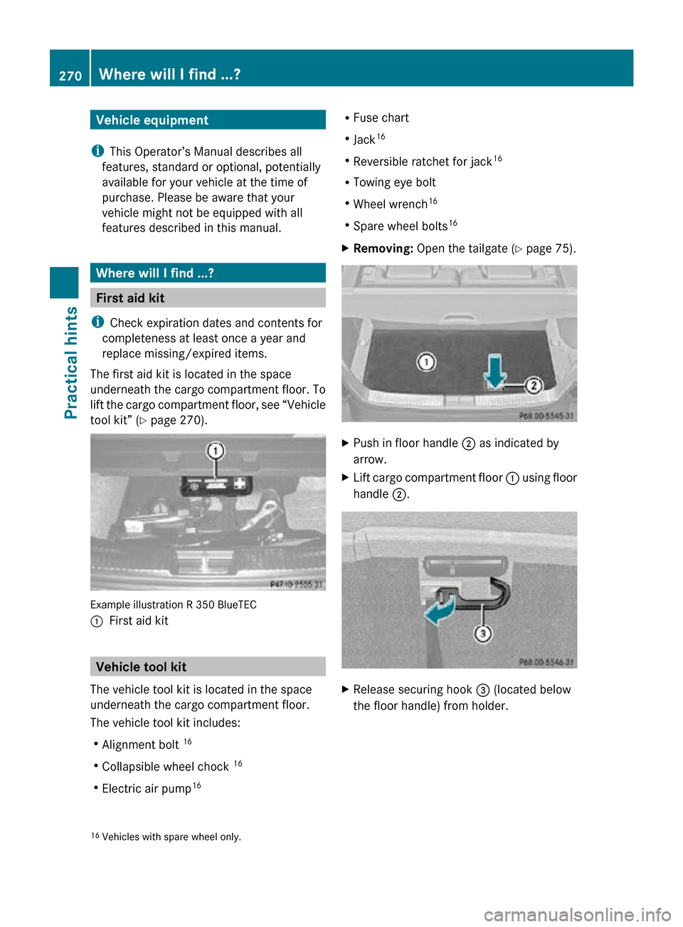
The first aid kit is located in the space
underneath the cargo compartment floor. To
lift the cargo compartment floor, see “Vehicle
tool kit” (Y page 270). Example illustration R 350 BlueTEC
:
First aid kit Vehicle tool kit
The vehicle tool kit is located in the space
underneath the cargo compartment floor.
The vehicle tool kit includes:
R Alignment bolt 16
R Collapsible wheel chock 16
R Electric air pump 16 R
Fuse chart
R Jack 16
R Reversible ratchet for jack 16
R Towing eye bolt
R Wheel wrench 16
R Spare wheel bolts 16
X Removing: Open the tailgate ( Y page 75). X
Push in floor handle ; as indicated by
arrow.
X Lift cargo compartment floor : using floor
handle ;. X
Release securing hook = (located below
the floor handle) from holder.
16 Vehicles with spare wheel only. 270
Where will I find ...?Practical hints
251_AKB; 4; 52, en-US
d2ureepe,
Version: 2.11.8.1 2009-03-23T09:22:52+01:00 - Seite 270
Page 273 of 364
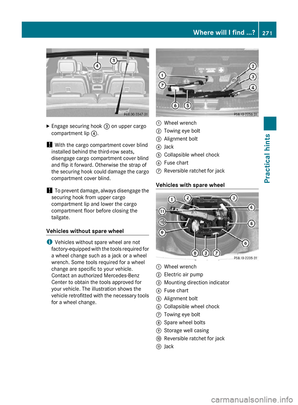
X
Engage securing hook = on upper cargo
compartment lip ?.
! With the cargo compartment cover blind
installed behind the third-row seats,
disengage cargo compartment cover blind
and flip it forward. Otherwise the strap of
the securing hook could damage the cargo
compartment cover blind.
! To prevent damage, always disengage the
securing hook from upper cargo
compartment lip and lower the cargo
compartment floor before closing the
tailgate.
Vehicles without spare wheel i
Vehicles without spare wheel are not
factory-equipped with the tools required for
a wheel change such as a jack or a wheel
wrench. Some tools required for a wheel
change are specific to your vehicle.
Contact an authorized Mercedes-Benz
Center to obtain the tools approved for
your vehicle. The illustration shows the
vehicle retrofitted with the necessary tools
for a wheel change. :
Wheel wrench
; Towing eye bolt
= Alignment bolt
? Jack
A Collapsible wheel chock
B Fuse chart
C Reversible ratchet for jack
Vehicles with spare wheel :
Wheel wrench
; Electric air pump
= Mounting direction indicator
? Fuse chart
A Alignment bolt
B Collapsible wheel chock
C Towing eye bolt
D Spare wheel bolts
E Storage well casing
F Reversible ratchet for jack
G Jack Where will I find ...?
271Practical hints
251_AKB; 4; 52, en-US
d2ureepe, Version: 2.11.8.1 2009-03-23T09:22:52+01:00 - Seite 271 Z
Page 274 of 364
Collapsible wheel chock
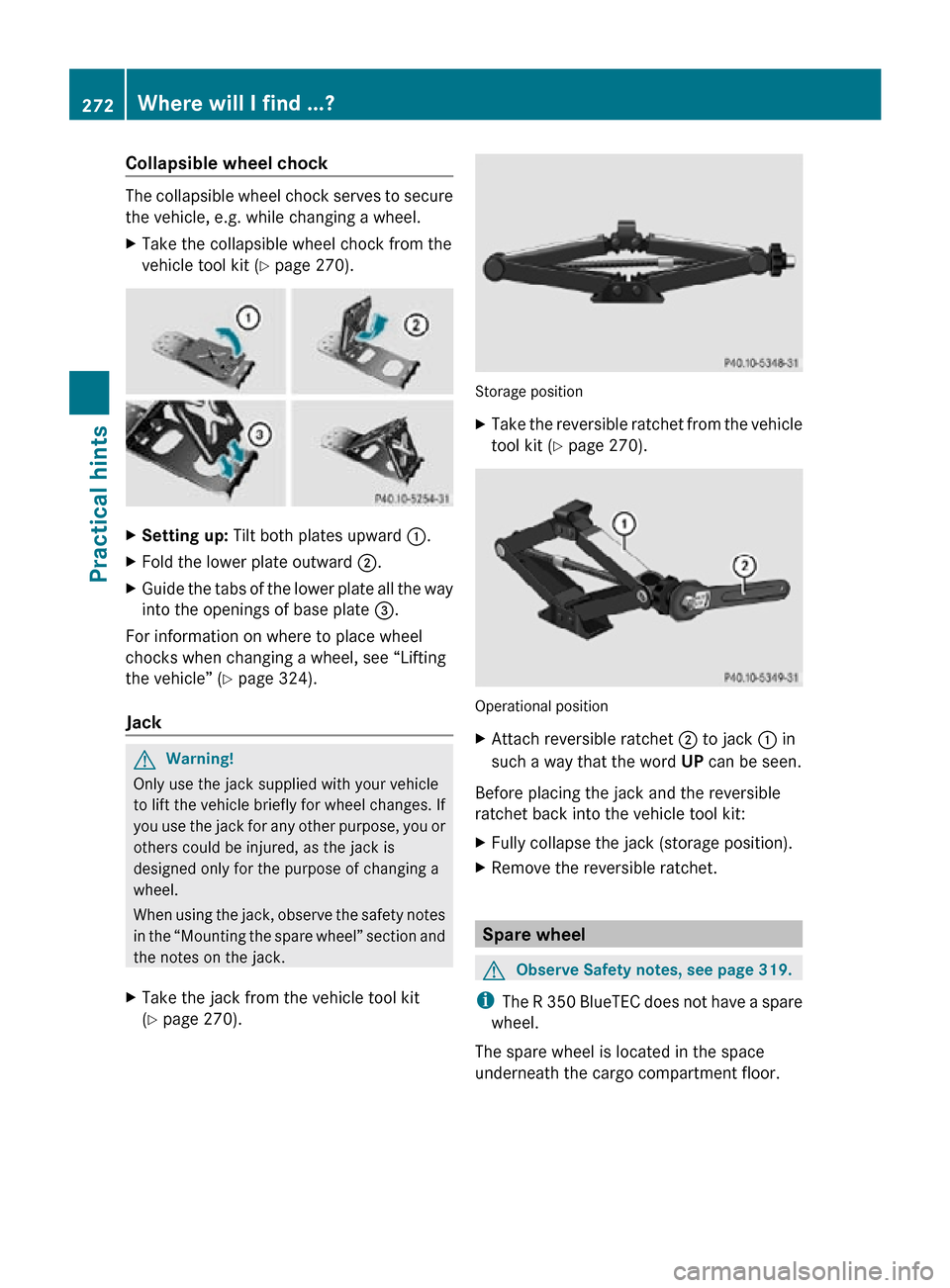
The collapsible wheel chock serves to secure
the vehicle, e.g. while changing a wheel.
X
Take the collapsible wheel chock from the
vehicle tool kit (Y page 270). X
Setting up: Tilt both plates upward :.
X Fold the lower plate outward ;.
X Guide the tabs of the lower plate all the way
into the openings of base plate =.
For information on where to place wheel
chocks when changing a wheel, see “Lifting
the vehicle” ( Y page 324).
Jack G
Warning!
Only use the jack supplied with your vehicle
to lift the vehicle briefly for wheel changes. If
you use the jack for any other purpose, you or
others could be injured, as the jack is
designed only for the purpose of changing a
wheel.
When using the jack, observe the safety notes
in the “Mounting the spare wheel” section and
the notes on the jack.
X Take the jack from the vehicle tool kit
(Y page 270). Storage position
X
Take the reversible ratchet from the vehicle
tool kit ( Y page 270). Operational position
X
Attach reversible ratchet ; to jack : in
such a way that the word UP can be seen.
Before placing the jack and the reversible
ratchet back into the vehicle tool kit:
X Fully collapse the jack (storage position).
X Remove the reversible ratchet. Spare wheel
G
Observe Safety notes, see page 319.
i The R 350 BlueTEC does not have a spare
wheel.
The spare wheel is located in the space
underneath the cargo compartment floor. 272
Where will I find ...?Practical hints
251_AKB; 4; 52, en-US
d2ureepe,
Version: 2.11.8.1 2009-03-23T09:22:52+01:00 - Seite 272
Page 275 of 364
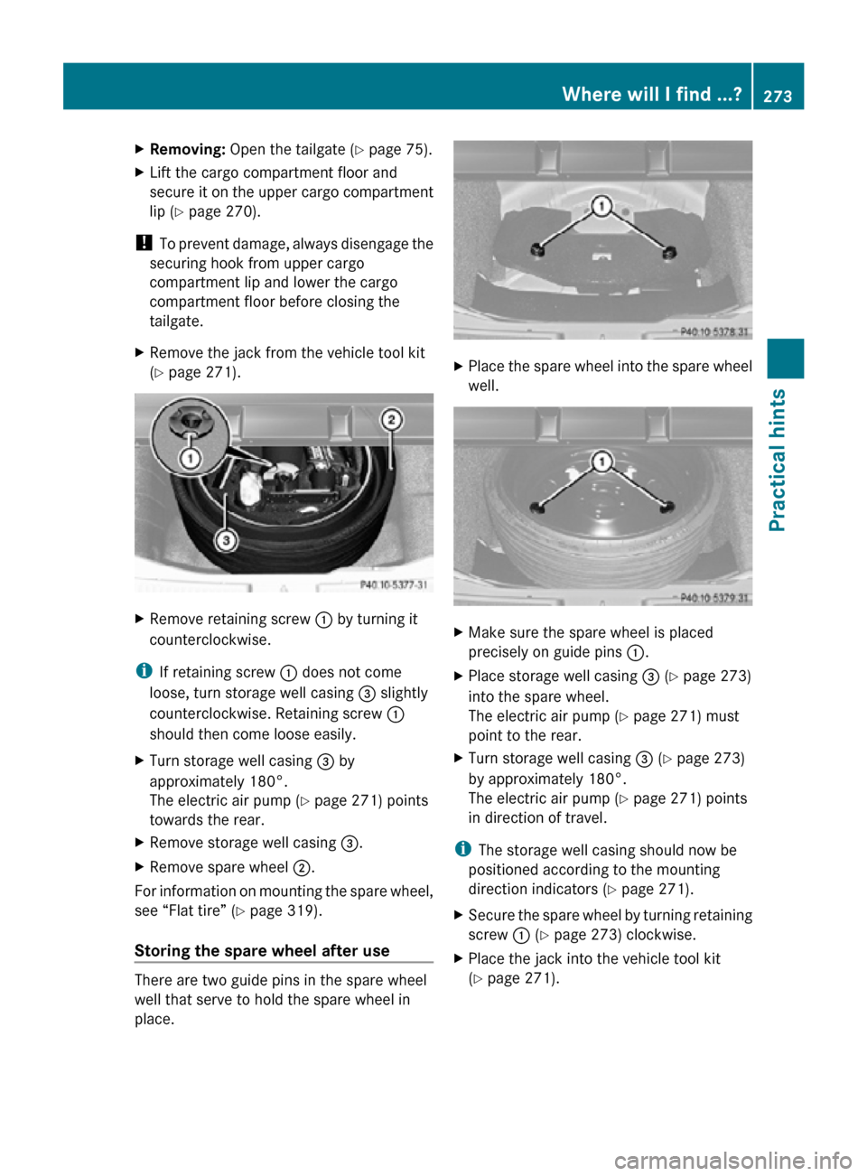
X
Removing: Open the tailgate ( Y page 75).
X Lift the cargo compartment floor and
secure it on the upper cargo compartment
lip ( Y page 270).
! To prevent damage, always disengage the
securing hook from upper cargo
compartment lip and lower the cargo
compartment floor before closing the
tailgate.
X Remove the jack from the vehicle tool kit
(Y page 271). X
Remove retaining screw : by turning it
counterclockwise.
i If retaining screw : does not come
loose, turn storage well casing = slightly
counterclockwise. Retaining screw :
should then come loose easily.
X Turn storage well casing = by
approximately 180°.
The electric air pump ( Y page 271) points
towards the rear.
X Remove storage well casing =.
X Remove spare wheel ;.
For information on mounting the spare wheel,
see “Flat tire” ( Y page 319).
Storing the spare wheel after use There are two guide pins in the spare wheel
well that serve to hold the spare wheel in
place. X
Place the spare wheel into the spare wheel
well. X
Make sure the spare wheel is placed
precisely on guide pins :.
X Place storage well casing = (Y page 273)
into the spare wheel.
The electric air pump ( Y page 271) must
point to the rear.
X Turn storage well casing = (Y page 273)
by approximately 180°.
The electric air pump ( Y page 271) points
in direction of travel.
i The storage well casing should now be
positioned according to the mounting
direction indicators (Y page 271).
X Secure the spare wheel by turning retaining
screw : (Y page 273) clockwise.
X Place the jack into the vehicle tool kit
(Y page 271). Where will I find ...?
273Practical hints
251_AKB; 4; 52, en-US
d2ureepe, Version: 2.11.8.1 2009-03-23T09:22:52+01:00 - Seite 273 Z
Page 286 of 364
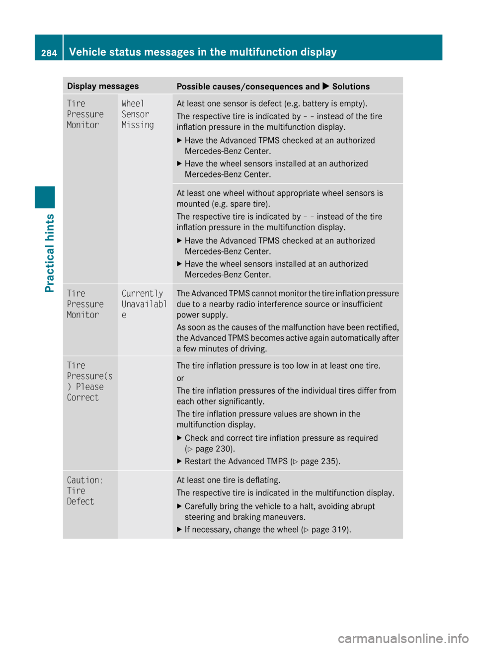
Display messages
Possible causes/consequences and
X SolutionsTire
Pressure
Monitor Wheel
Sensor
Missing At least one sensor is defect (e.g. battery is empty).
The respective tire is indicated by
– – instead of the tire
inflation pressure in the multifunction display.
X Have the Advanced TPMS checked at an authorized
Mercedes-Benz Center.
X Have the wheel sensors installed at an authorized
Mercedes-Benz Center. At least one wheel without appropriate wheel sensors is
mounted (e.g. spare tire).
The respective tire is indicated by
– – instead of the tire
inflation pressure in the multifunction display.
X Have the Advanced TPMS checked at an authorized
Mercedes-Benz Center.
X Have the wheel sensors installed at an authorized
Mercedes-Benz Center. Tire
Pressure
Monitor Currently
Unavailabl
e The Advanced TPMS cannot monitor the tire inflation pressure
due to a nearby radio interference source or insufficient
power supply.
As
soon as the causes of the malfunction have been rectified,
the Advanced TPMS becomes active again automatically after
a few minutes of driving. Tire
Pressure(s
) Please
Correct The tire inflation pressure is too low in at least one tire.
or
The tire inflation pressures of the individual tires differ from
each other significantly.
The tire inflation pressure values are shown in the
multifunction display.
X
Check and correct tire inflation pressure as required
(Y page 230).
X Restart the Advanced TMPS ( Y page 235).Caution:
Tire
Defect At least one tire is deflating.
The respective tire is indicated in the multifunction display.
X
Carefully bring the vehicle to a halt, avoiding abrupt
steering and braking maneuvers.
X If necessary, change the wheel (Y page 319). 284
Vehicle status messages in the multifunction displayPractical hints
251_AKB; 4; 52, en-US
d2ureepe,
Version: 2.11.8.1 2009-03-23T09:22:52+01:00 - Seite 284
Page 321 of 364
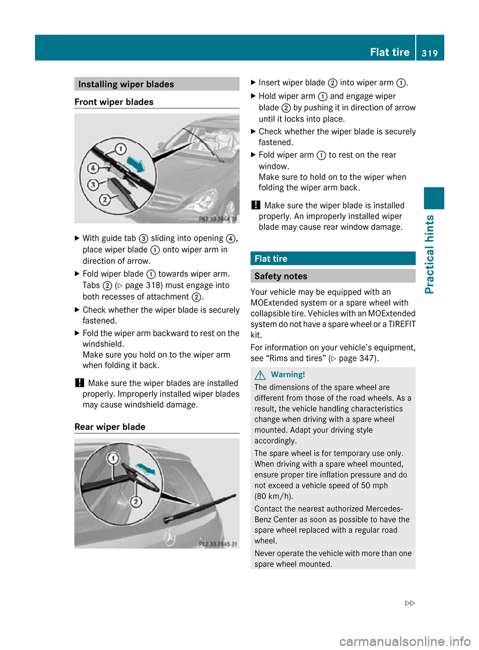
Installing wiper blades
Front wiper blades X
With guide tab = sliding into opening ?,
place wiper blade : onto wiper arm in
direction of arrow.
X Fold wiper blade : towards wiper arm.
Tabs ; (Y page 318) must engage into
both recesses of attachment ;.
X Check whether the wiper blade is securely
fastened.
X Fold the wiper arm backward to rest on the
windshield.
Make sure you hold on to the wiper arm
when folding it back.
! Make sure the wiper blades are installed
properly. Improperly installed wiper blades
may cause windshield damage.
Rear wiper blade X
Insert wiper blade ; into wiper arm :.
X Hold wiper arm : and engage wiper
blade ; by pushing it in direction of arrow
until it locks into place.
X Check whether the wiper blade is securely
fastened.
X Fold wiper arm : to rest on the rear
window.
Make sure to hold on to the wiper when
folding the wiper arm back.
! Make sure the wiper blade is installed
properly. An improperly installed wiper
blade may cause rear window damage. Flat tire
Safety notes
Your vehicle may be equipped with an
MOExtended system or a spare wheel with
collapsible tire. Vehicles with an MOExtended
system do not have a spare wheel or a TIREFIT
kit.
For information on your vehicle’s equipment,
see “Rims and tires” ( Y page 347). G
Warning!
The dimensions of the spare wheel are
different from those of the road wheels. As a
result, the vehicle handling characteristics
change when driving with a spare wheel
mounted. Adapt your driving style
accordingly.
The spare wheel is for temporary use only.
When driving with a spare wheel mounted,
ensure proper tire inflation pressure and do
not exceed a vehicle speed of 50 mph
(80 km/h).
Contact the nearest authorized Mercedes-
Benz Center as soon as possible to have the
spare wheel replaced with a regular road
wheel.
Never operate the vehicle with more than one
spare wheel mounted. Flat tire
319Practical hints
251_AKB; 4; 52, en-US
d2ureepe, Version: 2.11.8.1 2009-03-23T09:22:52+01:00 - Seite 319 Z
Page 322 of 364
Do not switch off the ESP
®
when a spare
wheel is mounted. G
Warning!
Vehicles with AIRMATIC:
Do not open or close any doors or the tailgate
while mounting a spare wheel. The vehicle
could rise or lower to a previously selected
level. You or others could be injured as a
result. Preparing the vehicle
X Vehicles with AIRMATIC:
Make sure the vehicle level is set to
highway level
(Y page 153).
X Whenever possible, park the vehicle in a
safe
distance from moving traffic on a hard,
flat surface.
X Turn on the hazard warning flasher.
X Turn the steering wheel so that the front
wheels are in a straight-ahead position.
X Engage the parking brake.
X Shift the automatic transmission into park
position P.
X Turn off the engine.
X Remove the SmartKey from the starter
switch.
or
X Vehicles with KEYLESS-GO: Open the
driver’s
door (this puts the starter switch in
position 0, same as with the SmartKey
removed from the starter switch). The
driver’s door can then be closed again.
Open doors only when conditions are safe
to do so.
X Vehicles with KEYLESS-GO: Remove the
KEYLESS-GO start/stop button from the
starter switch.
X Have any passenger exit the vehicle at a
safe distance from the roadway. Open
doors only when conditions are safe to do
so.
i Vehicles retrofitted with TIREFIT kit: Only use the power outlet in the second-
row footwell for electric air pump
operation.
You can use the power outlet even when
the ignition is switched off, e.g. in order to
inflate the collapsible tire.
An emergency shut-off feature is designed
to prevent the vehicle’s on-board voltage
from dropping below a minimum level. If
the on-board voltage drops to this
minimum level, the power outlets are
switched
off automatically to help preserve
engine starting power. Sealing tires with TIREFIT
This section applies to vehicles retrofitted
with a TIREFIT kit only.
Small
tire punctures, particularly those in the
tread, can be sealed with TIREFIT.
TIREFIT can be used in ambient temperatures
down to -4‡ (-20†). G
Warning!
TIREFIT is a limited repair device. TIREFIT
cannot be used for cuts or punctures larger
than approximately 0.16 in (4 mm) and tire
damage
caused by driving with extremely low
tire inflation pressure, or on a flat tire, or a
damaged wheel.
Do not drive the vehicle under such
circumstances.
Contact the nearest authorized Mercedes-
Benz Center for assistance or call Roadside
Assistance.
X Foreign objects (e.g. screws or nails)
should not be removed from the tire.
X Take the TIREFIT kit, the sticker, and the
electric air pump out of the vehicle. 320
Flat tire
Practical hints
251_AKB; 4; 52, en-US
d2ureepe,
Version: 2.11.8.1 2009-03-23T09:22:52+01:00 - Seite 320