2010 MERCEDES-BENZ R320 radio
[x] Cancel search: radioPage 216 of 364
X
Step 4: Using both hands, simultaneously
press hand-held remote control button B
and the desired signal transmitter button
(;, = or ?). Do not release the buttons
until step 5 is completed.
Indicator
lamp : will flash, first slowly and
then rapidly.
i Indicator lamp : flashes immediately
the first time the signal transmitter button
is programmed. If this button has already
been programmed, the indicator lamp will
start flashing after 20 seconds.
X Step 5: After indicator lamp : changes
from a slow to a rapidly flashing light,
release the hand-held remote control
button and the signal transmitter button.
X Step 6: Press and hold the just-trained
signal
transmitter button (;, = or ?) and
observe indicator lamp :.
If indicator lamp : stays on constantly,
programming is complete and your device
should activate when the respective signal
transmitter button ( ;, = or ?) is pressed
and released.
i If indicator lamp : flashes rapidly for
approximately
2 seconds and then turns to
a constant light, continue with
programming steps 8 through 12 as your
garage door opener may be equipped with
the “rolling code” feature.
X Step 7: To program the remaining two
signal
transmitter buttons, repeat the steps
above starting with step 3.
Rolling code programming
To
train a garage door opener (or other rolling
code devices) with the rolling code feature,
follow these instructions after completing the
“Programming” portion (steps 1 through 6) of
this text. For your convenience and to
complete the procedure faster, you might
want to have someone assist you. X
Step 8:
Locate the “training” button on the
garage door opener motor head unit.
i Exact
location and color of the button may
vary by garage door opener brand.
Depending on manufacturer, the “training”
button may also be referred to as “learn” or
“smart” button. If there is difficulty locating
the transmitting button, refer to the garage
door opener Operator’s Manual.
X Step 9: Press the “training” button on the
garage door opener motor head unit.
The “training light” is activated.
You have 30 seconds to initiate the
following two steps.
X Step 10: Return to the vehicle and firmly
press, hold for 2 seconds and release the
programmed
signal transmitter button (;,
= or ?).
X Step 11: Press, hold for 2 seconds and
release same signal transmitter button a
second time to complete the training
process.
i Some garage door openers (or other
rolling
code equipped devices) may require
you to press, hold for 2 seconds and
release the same signal transmitter button
a third time to complete the training
process.
X Step 12: Confirm the garage door
operation by pressing the programmed
signal transmitter button ( ;, = or ?).
X Step 13: To program the remaining two
signal
transmitter buttons, repeat the steps
above starting with step 3.
Gate operator/Canadian programming
Canadian radio-frequency laws require
transmitter signals to “time-out” (or quit)
after several seconds of transmission which
may not be long enough for the integrated
signal
transmitter to pick up the signal during
programming. Similar to this Canadian law,
some U.S. gate operators are designed to
“time-out” in the same manner. 214
Useful features
Controls in detail
251_AKB; 4; 52, en-US
d2ureepe,
Version: 2.11.8.1 2009-03-23T09:22:52+01:00 - Seite 214
Page 218 of 364
control is compatible with radio-frequency
devices operating between 280-390 MHz
.
R Put a new battery in hand-held remote
control A. This will increase the likelihood
of the hand-held remote control sending a
stronger and more accurate signal to the
integrated remote control.
R While performing step 3, hold hand-held
remote control A at different lengths and
angles from the signal transmitter button
(;, = or ?) you are programming.
Attempt varying angles at the distance of 2
to 12 inches (5 to 30 cm) away or the same
angle at varying distances.
R If another hand-held remote control is
available for the same device, try the
programming steps again using that other
hand-held remote control. Make sure new
batteries are in the hand-held remote
control before beginning the procedure.
R Straighten the antenna wire from the
garage door opener assembly. This may
help improve transmitting and/or receiving
signals.
i Certain types of garage door openers are
incompatible with the integrated remote
control. If you should experience further
difficulties with programming the
integrated remote control, contact an
authorized Mercedes-Benz Center, or call
the Mercedes-Benz Customer Assistance
Center (in the USA) at
1-800-FOR-MERCedes, or the HomeLink ®
Hotline (in the USA) at 1-800-355-3515, or
the Customer Service (in Canada) at
1-800-387-0100,. i
USA only:
This device complies with Part 15 of the
FCC Rules
. Operation is subject to the
following two conditions:
1. This device may not cause harmful interference, and
2. this device must accept any interference received, including
interference that may cause undesired
operation.
Any unauthorized modification to this
device could void the user’s authority to
operate the equipment.
i Canada only:
This device complies with RSS-210 of
Industry Canada. Operation is subject to
the following two conditions:
1. This device may not cause interference, and
2. this device must accept any interference received, including
interference that may cause undesired
operation of the device.
Any unauthorized modification to this
device could void the user’s authority to
operate the equipment. Compass
X Calling up the compass: Press button
V
or U on the multifunction steering
wheel repeatedly until the AIRMATIC/
Compass menu appears in the
multifunction display.
The compass displays the direction into
which the vehicle is currently traveling: N,
NE, E, SE, S, SW, W, or NW. 216
Useful features
Controls in detail
251_AKB; 4; 52, en-US
d2ureepe,
Version: 2.11.8.1 2009-03-23T09:22:52+01:00 - Seite 216
Page 236 of 364
malfunction using the TPMS telltale
flashing and illumination sequence.
The telltale extinguishes after a few
minutes driving if the malfunction has been
corrected.
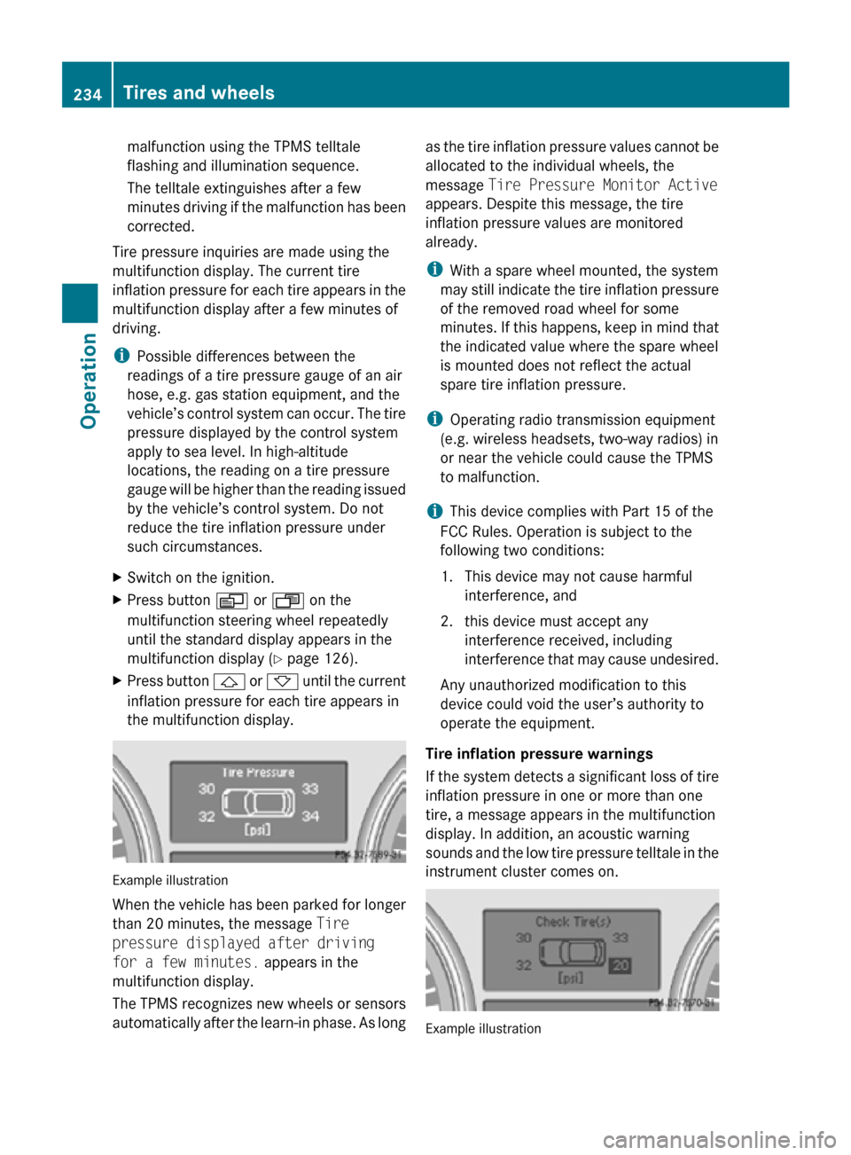
Tire pressure inquiries are made using the
multifunction display. The current tire
inflation pressure for each tire appears in the
multifunction display after a few minutes of
driving.
i Possible differences between the
readings of a tire pressure gauge of an air
hose, e.g. gas station equipment, and the
vehicle’s control system can occur. The tire
pressure displayed by the control system
apply to sea level. In high-altitude
locations, the reading on a tire pressure
gauge will be higher than the reading issued
by the vehicle’s control system. Do not
reduce the tire inflation pressure under
such circumstances.
X Switch on the ignition.
X Press button V or U on the
multifunction steering wheel repeatedly
until the standard display appears in the
multifunction display ( Y page 126).
X Press button & or * until the current
inflation pressure for each tire appears in
the multifunction display. Example illustration
When the vehicle has been parked for longer
than 20 minutes, the message Tire
pressure displayed after driving
for a few minutes. appears in the
multifunction display.
The TPMS recognizes new wheels or sensors
automatically after the learn-in phase. As long as the tire inflation pressure values cannot be
allocated to the individual wheels, the
message
Tire Pressure Monitor Active
appears. Despite this message, the tire
inflation pressure values are monitored
already.
i With a spare wheel mounted, the system
may still indicate the tire inflation pressure
of the removed road wheel for some
minutes. If this happens, keep in mind that
the indicated value where the spare wheel
is mounted does not reflect the actual
spare tire inflation pressure.
i Operating radio transmission equipment
(e.g. wireless headsets, two-way radios) in
or near the vehicle could cause the TPMS
to malfunction.
i This device complies with Part 15 of the
FCC Rules. Operation is subject to the
following two conditions:
1. This device may not cause harmful interference, and
2. this device must accept any interference received, including
interference that may cause undesired.
Any unauthorized modification to this
device could void the user’s authority to
operate the equipment.
Tire inflation pressure warnings
If the system detects a significant loss of tire
inflation pressure in one or more than one
tire, a message appears in the multifunction
display. In addition, an acoustic warning
sounds and the low tire pressure telltale in the
instrument cluster comes on. Example illustration234
Tires and wheelsOperation
251_AKB; 4; 52, en-US
d2ureepe,
Version: 2.11.8.1 2009-03-23T09:22:52+01:00 - Seite 234
Page 251 of 364
radio, and heater, to the extent that these
items are available as factory-installed
equipment (whether installed or not).
Air pressure
The amount of air inside the tire pressing
outward on each square inch of the tire. Air
pressure is expressed in pounds per square
inch (psi), kilopascal (kPa), or bar.
Aspect ratio
Dimensional relationship between tire
section height and section width expressed
in percentage.
Bar
Metric unit for air pressure. There are
14.5038 pounds per square inch (psi) to
1
bar; there are 100 kilopascals (kPa) to 1 bar.
Bead The tire bead contains steel wires wrapped by
steel cords that hold the tire onto the rim.
Cold tire inflation pressure
Tire inflation pressure when your vehicle has
been sitting for at least 3 hours or driven no
more than 1 mile (1.6 km).
Curb weight
The weight of a motor vehicle with standard
equipment including the maximum capacity
of fuel, oil, and coolant, and, if so equipped,
air conditioning and additional optional
equipment, but without passengers and
cargo.
DOT (Department of Transportation)
A tire branding symbol which denotes the tire
meets requirements of the U.S. Department
of Transportation. GAWR (Gross Axle Weight Rating) The GAWR is the maximum permissible axle
weight.
The gross vehicle weight on each axle
must never exceed the GAWR for the front
and rear axle indicated on the certification
label located on the driver’s door B-pillar.
GTW (Gross Trailer Weight) The GTW is the weight of the trailer plus the
weight of all cargo, equipment, luggage etc.
loaded on the trailer.
GVW (Gross Vehicle Weight)
The GVW comprises the weight of the vehicle
including fuel, tools, spare wheel, installed
accessories, passengers and cargo and, if
applicable,
trailer tongue load. The GVW must
never exceed the GVWR indicated on the
certification label located on the driver’s door
B-pillar.
GVWR (Gross Vehicle Weight Rating) This is the maximum permissible vehicle
weight of the fully loaded vehicle (weight of
the
vehicle including all options, passengers,
fuel, and cargo and, if applicable, trailer
tongue load). It is indicated on the
certification label located on the driver’s door
B-pillar.
Kilopascal (kPa) Metric unit for air pressure. There are 6.9 kPa
to 1 psi; another metric unit for air pressure
is bar. There are 100 kilopascals (kPa) to
1 bar.
Load index
Numerical code associated with the
maximum load a tire can support.
Maximum load rating
The maximum load in kilograms and pounds
that can be carried by the tire. Tires and wheels
249
Operation
251_AKB; 4; 52, en-US
d2ureepe, Version: 2.11.8.1 2009-03-23T09:22:52+01:00 - Seite 249 Z
Page 262 of 364
Control and operation of radio
transmitter
Safety notes G
Warning!
Please do not forget that your primary
responsibility is to drive the vehicle. A driver’s
attention to the road must always be his/her
primary focus when driving. For your safety
and the safety of others, we recommend that
you pull over to a safe location and stop
before placing or taking a telephone call.
If you choose to use the telephone 15
while
driving, please use the hands-free device and
only use the telephone when road, weather
and traffic conditions permit. Some
jurisdictions prohibit the driver from using a
mobile telephone while driving a vehicle.
Only operate the COMAND 15
(Cockpit
Management and Data System) if road,
weather and traffic conditions permit.
Otherwise, you may not be able to observe
traffic conditions and could endanger yourself
and others.
Bear in mind that at a speed of just 30 mph
(approximately 50 km/h), your vehicle is
covering a distance of 44 feet (approximately
14 m) every second. Emission control
Certain systems of the engine serve to keep
the toxic components of the exhaust gases
within permissible limits required by law.
These systems will function properly only
when
maintained strictly according to factory
specifications. Any adjustments on the
engine should, therefore, be carried out only
by qualified Mercedes-Benz Center
authorized technicians.
Engine adjustments should not be altered in
any way. Moreover, the specified service
procedures must be carried out regularly according to Mercedes-Benz servicing
requirements. For details refer to the
Maintenance Booklet. G
Warning!
Inhalation of exhaust gas is hazardous to your
health. All exhaust gas contains carbon
monoxide (CO), and inhaling it can cause
unconsciousness and possible death.
Do
not run the engine in confined areas (such
as a garage) which are not properly ventilated.
If you think that exhaust gas fumes are
entering the vehicle while driving, have the
cause determined and corrected
immediately. If you must drive under these
conditions, drive only with at least one
window fully open at all times. Maintenance
Notes
The Maintenance System in your vehicle
tracks the distance driven and the time
elapsed since the last maintenance service.
It
calculates other maintenance service work
required, and calls for the next maintenance
service accordingly.
We strongly recommend that you have your
vehicle serviced at an authorized Mercedes-
Benz Center. Have it serviced in accordance
with the Maintenance Booklet at the times
called for by the maintenance service
indicator.
i Failure to have the vehicle maintained in
accordance with the Maintenance Booklet
and maintenance service indicator at the
designated times/mileage will result in
vehicle damage not covered by the
Mercedes-Benz Limited Warranty.
15 Observe all legal requirements. 260
Maintenance
Operation
251_AKB; 4; 52, en-US
d2ureepe,
Version: 2.11.8.1 2009-03-23T09:22:52+01:00 - Seite 260
Page 286 of 364
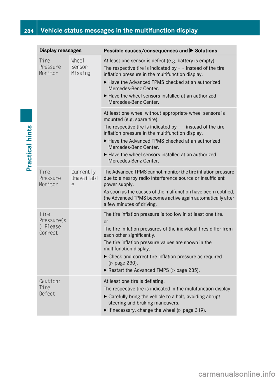
Display messages
Possible causes/consequences and
X SolutionsTire
Pressure
Monitor Wheel
Sensor
Missing At least one sensor is defect (e.g. battery is empty).
The respective tire is indicated by
– – instead of the tire
inflation pressure in the multifunction display.
X Have the Advanced TPMS checked at an authorized
Mercedes-Benz Center.
X Have the wheel sensors installed at an authorized
Mercedes-Benz Center. At least one wheel without appropriate wheel sensors is
mounted (e.g. spare tire).
The respective tire is indicated by
– – instead of the tire
inflation pressure in the multifunction display.
X Have the Advanced TPMS checked at an authorized
Mercedes-Benz Center.
X Have the wheel sensors installed at an authorized
Mercedes-Benz Center. Tire
Pressure
Monitor Currently
Unavailabl
e The Advanced TPMS cannot monitor the tire inflation pressure
due to a nearby radio interference source or insufficient
power supply.
As
soon as the causes of the malfunction have been rectified,
the Advanced TPMS becomes active again automatically after
a few minutes of driving. Tire
Pressure(s
) Please
Correct The tire inflation pressure is too low in at least one tire.
or
The tire inflation pressures of the individual tires differ from
each other significantly.
The tire inflation pressure values are shown in the
multifunction display.
X
Check and correct tire inflation pressure as required
(Y page 230).
X Restart the Advanced TMPS ( Y page 235).Caution:
Tire
Defect At least one tire is deflating.
The respective tire is indicated in the multifunction display.
X
Carefully bring the vehicle to a halt, avoiding abrupt
steering and braking maneuvers.
X If necessary, change the wheel (Y page 319). 284
Vehicle status messages in the multifunction displayPractical hints
251_AKB; 4; 52, en-US
d2ureepe,
Version: 2.11.8.1 2009-03-23T09:22:52+01:00 - Seite 284
Page 291 of 364
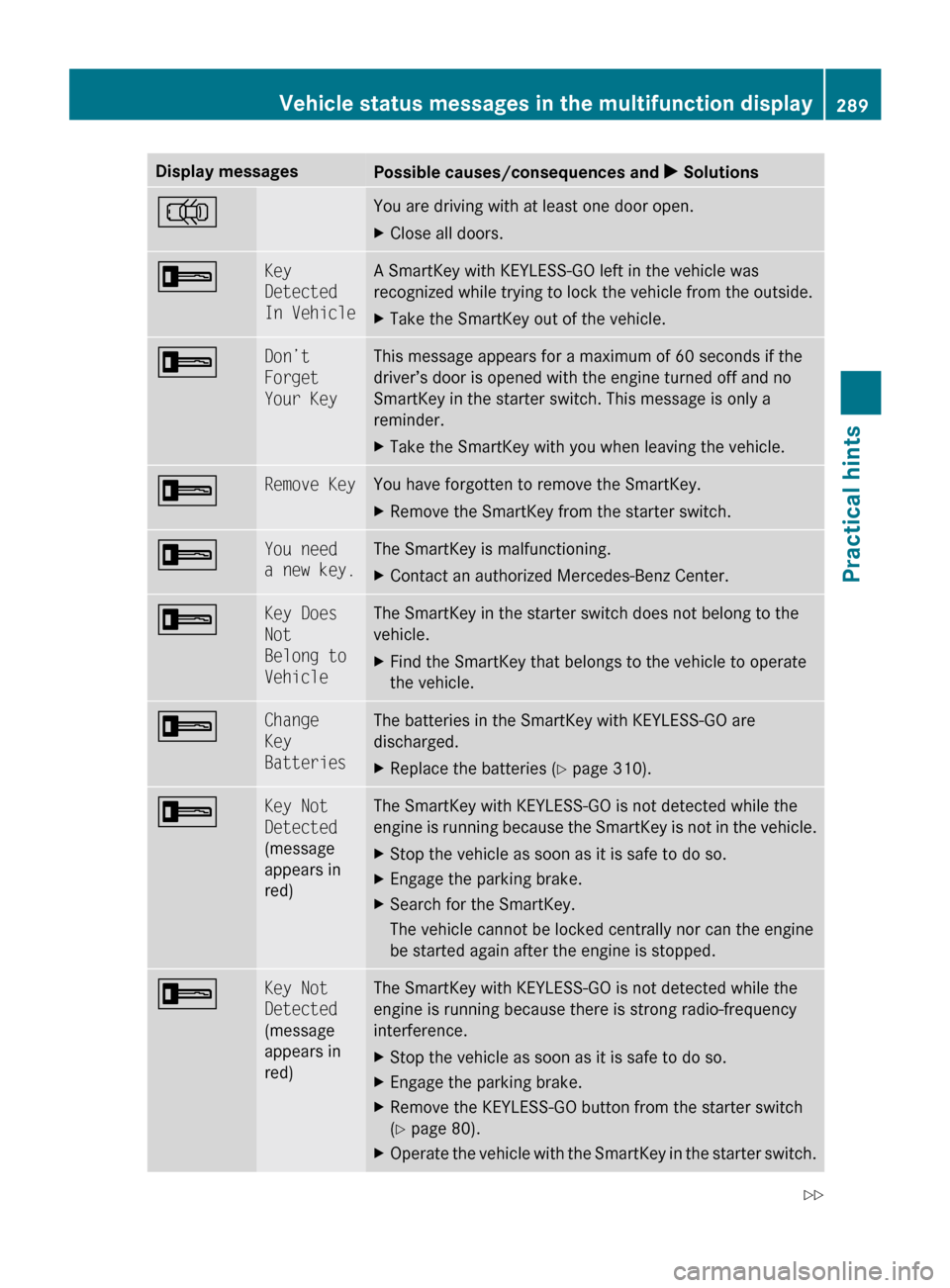
Display messages
Possible causes/consequences and
X Solutions; You are driving with at least one door open.
X
Close all doors. + Key
Detected
In Vehicle A SmartKey with KEYLESS-GO left in the vehicle was
recognized while trying to lock the vehicle from the outside.
X
Take the SmartKey out of the vehicle. + Don’t
Forget
Your Key This message appears for a maximum of 60 seconds if the
driver’s door is opened with the engine turned off and no
SmartKey in the starter switch. This message is only a
reminder.
X
Take the SmartKey with you when leaving the vehicle. + Remove Key You have forgotten to remove the SmartKey.
X
Remove the SmartKey from the starter switch. + You need
a new key. The SmartKey is malfunctioning.
X
Contact an authorized Mercedes-Benz Center. + Key Does
Not
Belong to
Vehicle The SmartKey in the starter switch does not belong to the
vehicle.
X
Find the SmartKey that belongs to the vehicle to operate
the vehicle. + Change
Key
Batteries The batteries in the SmartKey with KEYLESS-GO are
discharged.
X
Replace the batteries ( Y page 310).+ Key Not
Detected
(message
appears in
red) The SmartKey with KEYLESS-GO is not detected while the
engine
is running because the SmartKey is not in the vehicle.
X Stop the vehicle as soon as it is safe to do so.
X Engage the parking brake.
X Search for the SmartKey.
The vehicle cannot be locked centrally nor can the engine
be started again after the engine is stopped. + Key Not
Detected
(message
appears in
red) The SmartKey with KEYLESS-GO is not detected while the
engine is running because there is strong radio-frequency
interference.
X
Stop the vehicle as soon as it is safe to do so.
X Engage the parking brake.
X Remove the KEYLESS-GO button from the starter switch
(Y page 80).
X Operate the vehicle with the SmartKey in the starter switch. Vehicle status messages in the multifunction display
289
Practical hints
251_AKB; 4; 52, en-US
d2ureepe,Version: 2.11.8.1 2009-03-23T09:22:52+01:00 - Seite 289 Z