2010 MERCEDES-BENZ R320 key
[x] Cancel search: keyPage 319 of 364
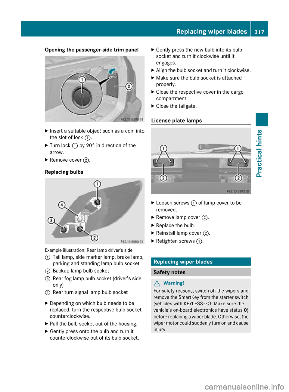
Opening the passenger-side trim panel
X
Insert a suitable object such as a coin into
the slot of lock :.
X Turn lock : by 90° in direction of the
arrow.
X Remove cover ;.
Replacing bulbs Example illustration: Rear lamp driver’s side
:
Tail lamp, side marker lamp, brake lamp,
parking and standing lamp bulb socket
; Backup lamp bulb socket
= Rear fog lamp bulb socket (driver’s side
only)
? Rear turn signal lamp bulb socket
X Depending on which bulb needs to be
replaced, turn the respective bulb socket
counterclockwise.
X Pull the bulb socket out of the housing.
X Gently press onto the bulb and turn it
counterclockwise out of its bulb socket. X
Gently press the new bulb into its bulb
socket and turn it clockwise until it
engages.
X Align the bulb socket and turn it clockwise.
X Make sure the bulb socket is attached
properly.
X Close the respective cover in the cargo
compartment.
X Close the tailgate.
License plate lamps X
Loosen screws : of lamp cover to be
removed.
X Remove lamp cover ;.
X Replace the bulb.
X Reinstall lamp cover ;.
X Retighten screws :. Replacing wiper blades
Safety notes
G
Warning!
For safety reasons, switch off the wipers and
remove the SmartKey from the starter switch
(vehicles with KEYLESS-GO: Make sure the
vehicle’s on-board electronics have status 0)
before replacing a wiper blade. Otherwise, the
wiper motor could suddenly turn on and cause
injury. Replacing wiper blades
317Practical hints
251_AKB; 4; 52, en-US
d2ureepe, Version: 2.11.8.1 2009-03-23T09:22:52+01:00 - Seite 317 Z
Page 320 of 364
G
Warning!
Wiper blades are components that are subject
to wear and tear. Replace the wiper blades
twice a year, preferably in the spring and fall.
Otherwise the windows will not be wiped
properly. As a result, you may not be able to
observe surrounding traffic conditions and
could cause an accident.
! Never open the hood when a front wiper
arm is folded forward.
Hold on to the wiper when folding a wiper
arm back. If released, the force of the
impact from the tensioning spring could
crack the windshield or the rear window.
Do not allow a wiper arm to contact the
windshield glass or the rear window
without a wiper blade inserted.
Mercedes-Benz recommends that you have
this work carried out at an authorized
Mercedes-Benz Center.
X Remove the SmartKey from the starter
switch.
Vehicles with KEYLESS-GO:
X Make sure the vehicle’s on-board
electronics have status 0 (Y page 80). Removing wiper blades
Front wiper blades !
Do not pull on the wiper blade inserts.
They could tear.
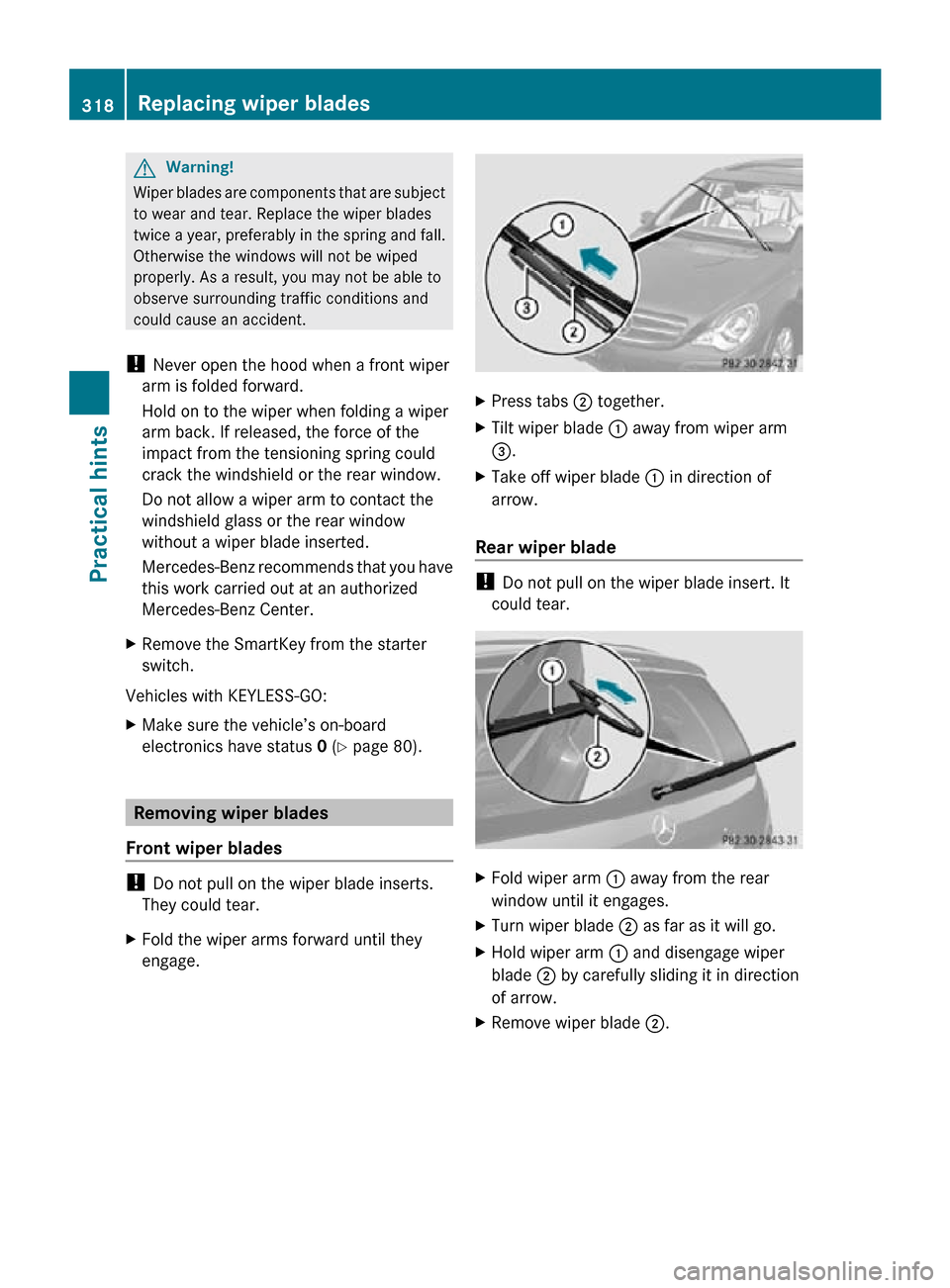
X Fold the wiper arms forward until they
engage. X
Press tabs ; together.
X Tilt wiper blade : away from wiper arm
=.
X Take off wiper blade : in direction of
arrow.
Rear wiper blade !
Do not pull on the wiper blade insert. It
could tear. X
Fold wiper arm : away from the rear
window until it engages.
X Turn wiper blade ; as far as it will go.
X Hold wiper arm : and disengage wiper
blade ; by carefully sliding it in direction
of arrow.
X Remove wiper blade ;.318
Replacing wiper bladesPractical hints
251_AKB; 4; 52, en-US
d2ureepe,
Version: 2.11.8.1 2009-03-23T09:22:52+01:00 - Seite 318
Page 322 of 364
Do not switch off the ESP
®
when a spare
wheel is mounted. G
Warning!
Vehicles with AIRMATIC:
Do not open or close any doors or the tailgate
while mounting a spare wheel. The vehicle
could rise or lower to a previously selected
level. You or others could be injured as a
result. Preparing the vehicle
X Vehicles with AIRMATIC:
Make sure the vehicle level is set to
highway level
(Y page 153).
X Whenever possible, park the vehicle in a
safe
distance from moving traffic on a hard,
flat surface.
X Turn on the hazard warning flasher.
X Turn the steering wheel so that the front
wheels are in a straight-ahead position.
X Engage the parking brake.
X Shift the automatic transmission into park
position P.
X Turn off the engine.
X Remove the SmartKey from the starter
switch.
or
X Vehicles with KEYLESS-GO: Open the
driver’s
door (this puts the starter switch in
position 0, same as with the SmartKey
removed from the starter switch). The
driver’s door can then be closed again.
Open doors only when conditions are safe
to do so.
X Vehicles with KEYLESS-GO: Remove the
KEYLESS-GO start/stop button from the
starter switch.
X Have any passenger exit the vehicle at a
safe distance from the roadway. Open
doors only when conditions are safe to do
so.
i Vehicles retrofitted with TIREFIT kit: Only use the power outlet in the second-
row footwell for electric air pump
operation.
You can use the power outlet even when
the ignition is switched off, e.g. in order to
inflate the collapsible tire.
An emergency shut-off feature is designed
to prevent the vehicle’s on-board voltage
from dropping below a minimum level. If
the on-board voltage drops to this
minimum level, the power outlets are
switched
off automatically to help preserve
engine starting power. Sealing tires with TIREFIT
This section applies to vehicles retrofitted
with a TIREFIT kit only.
Small
tire punctures, particularly those in the
tread, can be sealed with TIREFIT.
TIREFIT can be used in ambient temperatures
down to -4‡ (-20†). G
Warning!
TIREFIT is a limited repair device. TIREFIT
cannot be used for cuts or punctures larger
than approximately 0.16 in (4 mm) and tire
damage
caused by driving with extremely low
tire inflation pressure, or on a flat tire, or a
damaged wheel.
Do not drive the vehicle under such
circumstances.
Contact the nearest authorized Mercedes-
Benz Center for assistance or call Roadside
Assistance.
X Foreign objects (e.g. screws or nails)
should not be removed from the tire.
X Take the TIREFIT kit, the sticker, and the
electric air pump out of the vehicle. 320
Flat tire
Practical hints
251_AKB; 4; 52, en-US
d2ureepe,
Version: 2.11.8.1 2009-03-23T09:22:52+01:00 - Seite 320
Page 324 of 364
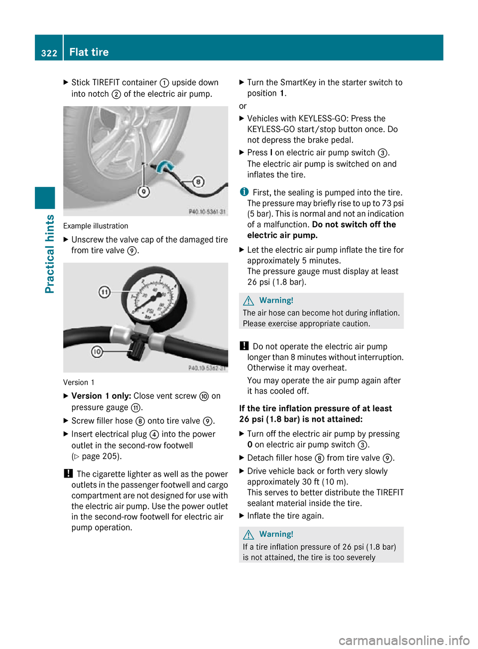
X
Stick TIREFIT container : upside down
into notch ; of the electric air pump. Example illustration
X
Unscrew the valve cap of the damaged tire
from tire valve E. Version 1
X
Version 1 only: Close vent screw F on
pressure gauge G.
X Screw filler hose D onto tire valve E.
X Insert electrical plug ? into the power
outlet in the second-row footwell
(Y page 205).
! The cigarette lighter as well as the power
outlets in the passenger footwell and cargo
compartment are not designed for use with
the electric air pump. Use the power outlet
in the second-row footwell for electric air
pump operation. X
Turn the SmartKey in the starter switch to
position 1.
or
X Vehicles with KEYLESS-GO: Press the
KEYLESS-GO start/stop button once. Do
not depress the brake pedal.
X Press I on electric air pump switch =.
The electric air pump is switched on and
inflates the tire.
i First, the sealing is pumped into the tire.
The pressure may briefly rise to up to 73 psi
(5 bar). This is normal and not an indication
of a malfunction. Do not switch off the
electric air pump.
X Let the electric air pump inflate the tire for
approximately 5 minutes.
The pressure gauge must display at least
26 psi (1.8 bar). G
Warning!
The air hose can become hot during inflation.
Please exercise appropriate caution.
! Do not operate the electric air pump
longer than 8 minutes without interruption.
Otherwise it may overheat.
You may operate the air pump again after
it has cooled off.
If the tire inflation pressure of at least
26 psi (1.8 bar) is not attained:
X Turn off the electric air pump by pressing
0 on electric air pump switch =.
X Detach filler hose D from tire valve E.
X Drive vehicle back or forth very slowly
approximately 30 ft (10 m).
This serves to better distribute the TIREFIT
sealant material inside the tire.
X Inflate the tire again. G
Warning!
If a tire inflation pressure of 26 psi (1.8 bar)
is not attained, the tire is too severely 322
Flat tirePractical hints
251_AKB; 4; 52, en-US
d2ureepe,
Version: 2.11.8.1 2009-03-23T09:22:52+01:00 - Seite 322
Page 331 of 364
!
The cigarette lighter as well as the power
outlets in the passenger footwell and cargo
compartment are not designed for use with
the electric air pump. Use the power outlet
in the second-row footwell for electric air
pump operation.
X Turn the SmartKey in the starter switch to
position 1.
or
X Vehicles with KEYLESS-GO: Press the
KEYLESS-GO start/stop button once. Do
not depress the brake pedal.
X Press I on electric air pump switch ;.
The electric air pump switches on and
inflates the collapsible tire.
X Inflate the collapsible tire to the
recommended tire inflation pressure as
specified for your vehicle
(Y page 350).
This should take approximately 5 minutes. G
Warning!
The air hose and the union nut can become
hot during inflation. Exercise proper caution
to avoid burning yourself when using the
equipment.
! Do not operate the electric air pump
longer
than 8 minutes without interruption.
Otherwise it may overheat.
You may operate the air pump again after
it has cooled off.
! Compare the recommended tire inflation
pressure for your vehicle with the tire
inflation pressure on the yellow label
located on the spare wheel rim.
If the tire inflation pressure on the yellow
label on the spare wheel rim differs from
the values given in this Operator’s Manual,
inflate the tire to the recommended tire
inflation pressure given on the yellow label
on the spare wheel rim. X
Press 0 on electric air pump switch ;.
X Turn the SmartKey in the starter switch to
position 0.
or
X Vehicles with KEYLESS-GO: Press the
KEYLESS-GO start/stop button twice. Do
not depress the brake pedal.
X Version 1 only:
If the tire inflation pressure
is above the recommended tire inflation
pressure as specified for your vehicle
(Y page 350), decrease tire pressure using
the vent screw on air hose ?.
X Version 2 only:
If the tire inflation pressure
is above the recommended tire inflation
pressure as specified for your vehicle
(Y page 350), decrease tire pressure using
deflate button B. G
Observe Safety notes, see page 230.
X Detach the electric air pump.
X Reinstall collapsible tire valve cap.
X Version 1 only: Store electrical plug =
and air hose ? behind flap :.
X Version 2 only: Store electrical plug =
and the air hose back into the pump
housing bottom.
X Place the electric air pump back in its
designated storage space.
X Lower the vehicle.
Lowering the vehicle G
Warning!
Inflate collapsible tire only after the wheel is
properly attached.
Inflate the collapsible tire using the electric
air pump before lowering the vehicle.
X Attach ratchet to vehicle jack so that the
word DOWN can be seen.
Lower the vehicle until the vehicle is resting
fully on its own weight:
X Turn ratchet in direction DOWN.
X Remove the jack. Flat tire
329
Practical hints
251_AKB; 4; 52, en-US
d2ureepe, Version: 2.11.8.1 2009-03-23T09:22:52+01:00 - Seite 329 Z
Page 333 of 364
After driving in emergency mode, you must
have the rims inspected by an authorized
Mercedes-Benz Center to check if they are
suitable for further use. The failed tire must
be replaced in any case.
When replacing individual or all tires on the
vehicle, make sure only tires marked with
“MOExtended” are mounted in the size
specified for your vehicle
(Y page 347). Bleeding the fuel system (diesel
engine only)
Driving
the vehicle until the fuel tank is empty
is not recommended. Otherwise, air may be
sucked into the fuel system. If this happens,
the malfunction indicator lamp = (USA
only) or ; (Canada only) comes on and the
engine may not start immediately after
refueling the vehicle.
After refueling:
X Make sure the automatic transmission is in
park position P.
The gear position indicator in the
multifunction display should be on P.
X Do not depress the accelerator.
X If necessary, remove the KEYLESS-GO
start/stop button from the starter switch.
X Turn the SmartKey in the starter switch to
position 2 for at least 10 seconds.
X Return the SmartKey in the starter switch
to position 0.
X Turn the SmartKey in the starter switch to
position 3
and hold it there for a maximum
of 40 seconds or until the engine runs
surge-free.
If the engine does not start:
X Wait for approximately 2 minutes.
X Turn the SmartKey in the starter switch to
position 3
and hold it there for a maximum
of 40 seconds or until the engine runs
surge-free. If the engine still does not start, do not make
any further attempts to start the engine.
Contact
an authorized Mercedes-Benz Center
or call Roadside Assistance ( Y page 210).
i When the malfunction indicator lamp
= (USA only) or ; (Canada only) in
the instrument cluster has been illuminated
for the above condition, it will remain
illuminated until the engine was cycled on
and off four times in a row. AdBlue
®
(diesel engine only)
The BlueTEC exhaust gas aftertreatment
system requires a reducing agent (AdBlue ®
)
in order to function properly. Refilling with
AdBlue ®
is part of the regular maintenance
service work. A tankful of AdBlue ®
should
suffice until the next maintenance service
under normal driving conditions.
When the AdBlue ®
tank is low, the message
Check Additive See Operator’s
Manual appears in the multifunction display.
When the AdBlue ®
level drops to the
minimum level, the message Remaining
Starts: 20 appears in the multifunction
display.
i When
the message Remaining Starts:
20 appears in the multifunction display, you
can start the engine 20 more times. If you
do not add AdBlue ®
, the engine cannot be
started beyond that point. Fill the
AdBlue ®
tank with approximately 1 gal
(3.79 l) AdBlue ®
(corresponds to
approximately 2 AdBlue ®
refill containers)
or have the AdBlue ®
tank filled by an
authorized Mercedes-Benz Center.
i For refilling outside the maintenance
service intervals, refill the AdBlue ®
tank
with approximately 1 gal (3.79 l) AdBlue ®
(corresponds to approximately 2 AdBlue ®
refill containers). AdBlue
®
(diesel engine only) 331
Practical hints
251_AKB; 4; 52, en-US
d2ureepe,
Version: 2.11.8.1 2009-03-23T09:22:52+01:00 - Seite 331 Z
Page 337 of 364
battery cover is non-removable. Do not
attempt to open the battery as otherwise
the battery will be damaged.
VRLA
batteries do not require topping-up of
the electrolyte level. They cannot be
opened to check the electrolyte level.
However, the battery condition must be
checked periodically by performing a
battery conductance test. Refer to
Maintenance Booklet for battery condition
testing intervals.
The factory-equipped battery may only be
replaced with a battery that
R has the same security features
R is of identical size
R is of identical voltage
R is of identical capacity
! As any other battery, the battery may
discharge if you do not operate the vehicle
for an extended period of time. Have the
battery disconnected at a qualified
workshop or an authorized Mercedes-Benz
Center in such a case. You may also
connect an accessory battery charge unit
expressly approved by Mercedes-Benz for
your vehicle model to maintain the battery
charge. Contact an authorized Mercedes-
Benz Center for further information.
The battery, the battery ventilation hose
and the lateral plug must always be
securely installed when the vehicle is in
operation.
! Never loosen or detach battery terminal
clamps while the engine is running or the
SmartKey is in the starter switch or
KEYLESS-GO button is in position 1.
Otherwise the alternator and other
electronic components could be severely
damaged.
Have the battery checked regularly at an
authorized Mercedes-Benz Center.
Refer to Maintenance Booklet for
maintenance intervals or contact an authorized Mercedes-Benz Center for
further information.
i After battery power was interrupted, do
the following:
R Set the clock
(Y page 133).
Vehicles with COMAND system with
navigation module: Time and date are set
automatically.
R Synchronize the door windows
(Y page 107).
R Synchronize the power tilt/sliding
sunroof (Y page 183).
R Synchronize the power tilt/sliding panel
(Y page 186).
R Synchronize the exterior rear view
mirrors (Y page 96). Charging the battery
G
Warning!
Never charge a battery while still installed in
the vehicle unless the accessory battery
charge unit approved by Mercedes-Benz is
being used. Gases may escape during
charging and could cause an explosion that
may
result in personal injury, paint damage or
corrosion.
An accessory battery charge unit specially
adapted for Mercedes-Benz vehicles and
tested and approved by Mercedes-Benz is
available. It permits the charging of the
battery in its installed position. Contact an
authorized Mercedes-Benz Center for
information and availability.
Charge battery in accordance with the
separate instructions for the accessory
battery charger.
Have the battery charged at an authorized
Mercedes-Benz Center. If you charge the
battery yourself, follow the operating
instructions for your charging device. Battery
335
Practical hints
251_AKB; 4; 52, en-US
d2ureepe, Version: 2.11.8.1 2009-03-23T09:22:52+01:00 - Seite 335 Z
Page 340 of 364
X
Slide cover A back onto negative terminal
B.
X Have the battery checked at the nearest
authorized Mercedes-Benz Center. Towing the vehicle
Safety notes
Mercedes-Benz
recommends that the vehicle
be transported with all wheels off the ground
using flatbed or appropriate wheel lift/dolly
equipment. This method is preferable to other
types of towing.
! To prevent damage during transport, do
not tie down vehicle by its chassis or
suspension parts.
If circumstances do not permit the
recommended towing methods, the vehicle
may be towed with all wheels on the ground
only so far as necessary to have the vehicle
moved to a safe location where the
recommended towing methods can be
employed.
! Before towing the vehicle observe the
following instructions:
R Do not tow-start the vehicle. You could
otherwise seriously damage the
automatic transmission which is not
covered by the Mercedes-Benz Limited
Warranty.
R Do not tow with sling-type equipment.
Towing with sling-type equipment over
bumpy roads will damage radiator and
supports.
R Towing of the vehicle should only be
done using the properly installed towing
eye bolt. Never attach a tow cable, tow
rope or tow rod to the vehicle chassis,
frame or suspension parts.
! Do not tow with one axle raised. Doing so
could damage the transfer case, which is
not covered by the Mercedes-Benz Limited Warranty. All wheels must be on or off the
ground.
Observe instructions for towing the
vehicle with all wheels on the ground. G
Warning!
With the engine not running, there is no power
assistance for the brake and steering
systems. In this case, it is important to keep
in mind that a considerably higher degree of
effort is necessary to brake and steer the
vehicle. Adapt your driving accordingly.
! Avoid pulling the vehicle abruptly or
diagonally, since it could result in damage
to the chassis alignment.
! Do not use the towing eye bolt for
recovery,
as this could damage the vehicle.
If in doubt, recover the vehicle with a crane.
i If the battery is disconnected or
discharged
R the SmartKey will not turn in the starter
switch
R the automatic transmission will remain in
park position P
For more information see “Battery”
(Y page 333) or “Jump starting”
(Y page 336). Installing towing eye bolt
Depending on whether you are towing a
vehicle
or you are being towed, the towing eye
bolt can be screwed into threaded holes
which are located behind covers on each
bumper.
The towing eye bolt is supplied with the
vehicle tool kit, located in the cargo
compartment underneath the cargo
compartment floor (Y page 270).
X Take the towing eye bolt out of the space
underneath the cargo compartment floor. 338
Towing the vehicle
Practical hints
251_AKB; 4; 52, en-US
d2ureepe,
Version: 2.11.8.1 2009-03-23T09:22:52+01:00 - Seite 338