2010 MERCEDES-BENZ GLK350 4MATIC tailgate
[x] Cancel search: tailgatePage 251 of 344
distance ahead than when driving without
a trailer.
Because your vehicle and trailer is longer
than your vehicle alone, you will also need
to go much farther ahead of the passed
vehicle before you can return to your lane.
Decoupling a trailer XMake sure the automatic transmission is in
park position P (Y page 103).XEngage the parking brake for the vehicle
( Y page 102).XClose all doors and the tailgate.XEngage the parking brake for the trailer.XDisconnect all electrical plug connectors.XDecouple the trailer.XMake sure that the trailer coupling is free
of load.
Driving abroad
If you plan to drive the vehicle outside the U.S.
or Canada, you should request dealer
network information for your destination from
any authorized Mercedes-Benz Center.
Control and operation of radio
transmitters
Safety notes
GWarning!
Please do not forget that your primary
responsibility is to drive the vehicle. A driver’s
attention to the road must always be his/her
primary focus when driving. For your safety
and the safety of others, we recommend that
you pull over to a safe location and stop
before placing or taking a telephone call.
If you choose to use the telephone 11
while
driving, please use the hands-free device and
only use the telephone when road, weather
and traffic conditions permit. Some
jurisdictions prohibit the driver from using a
mobile telephone while driving a vehicle.
Only operate the audio system or
COMAND 11
(Cockpit Management and Data
System) if road, weather and traffic
conditions permit. Otherwise, you may not be
able to observe traffic conditions and could
endanger yourself and others.
Bear in mind that at a speed of just 30 mph
(approximately 50 km/h), your vehicle is
covering a distance of 44 feet (approximately
14 m) every second.
Emission control
Certain systems of the engine serve to keep
the toxic components of the exhaust gases
within permissible limits required by law.
These systems will function properly only
when maintained strictly according to factory
specifications. Any adjustments on the
engine should, therefore, be carried out only
by qualified Mercedes-Benz Center
authorized technicians.
Engine adjustments should not be altered in
any way. Moreover, the specified service
procedures must be carried out regularly
according to Mercedes-Benz servicing
requirements. For details refer to the
Maintenance Booklet.
GWarning!
Inhalation of exhaust gas is hazardous to your
health. All exhaust gas contains carbon
monoxide (CO), and inhaling it can cause
unconsciousness and possible death.
Do not run the engine in confined areas (such
as a garage) which are not properly ventilated.
If you think that exhaust gas fumes are
entering the vehicle while driving, have the
cause determined and corrected
immediately. If you must drive under these
conditions, drive only with at least one
window fully open at all times.
11 Observe all legal requirements.Driving instructions249OperationX204_AKB; 3; 23, en-USd2ureepe,Version: 2.11.8.12009-07-16T19:16:58+02:00 - Seite 249Z
Page 262 of 344
Vehicle equipment
iThis Operator’s Manual describes all
features, standard or optional, potentially
available for your vehicle at the time of
purchase. Please be aware that your
vehicle might not be equipped with all
features described in this manual.
Where will I find ...?
First aid kit
iCheck expiration dates and contents for
completeness at least once a year and
replace missing/expired items.
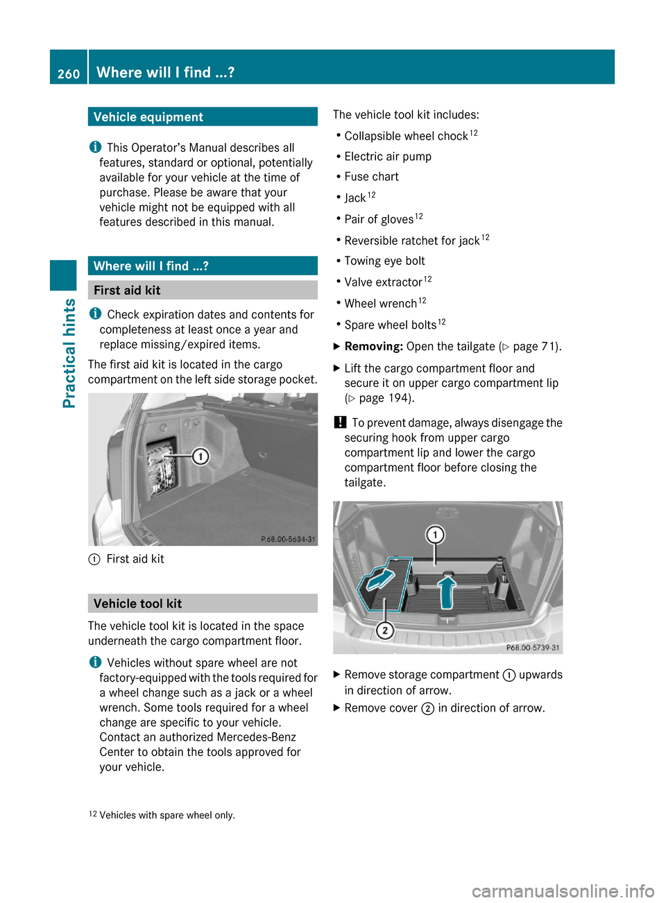
The first aid kit is located in the cargo
compartment on the left side storage pocket.
:First aid kit
Vehicle tool kit
The vehicle tool kit is located in the space
underneath the cargo compartment floor.
iVehicles without spare wheel are not
factory-equipped with the tools required for
a wheel change such as a jack or a wheel
wrench. Some tools required for a wheel
change are specific to your vehicle.
Contact an authorized Mercedes-Benz
Center to obtain the tools approved for
your vehicle.
The vehicle tool kit includes:
RCollapsible wheel chock12
RElectric air pump
RFuse chart
RJack12
RPair of gloves12
RReversible ratchet for jack12
RTowing eye bolt
RValve extractor12
RWheel wrench12
RSpare wheel bolts12
XRemoving: Open the tailgate (Y page 71).XLift the cargo compartment floor and
secure it on upper cargo compartment lip
(Y page 194).
! To prevent damage, always disengage the
securing hook from upper cargo
compartment lip and lower the cargo
compartment floor before closing the
tailgate.
XRemove storage compartment : upwards
in direction of arrow.
XRemove cover ; in direction of arrow.12Vehicles with spare wheel only.260Where will I find ...?Practical hints
X204_AKB; 3; 23, en-USd2ureepe,Version: 2.11.8.12009-07-16T19:16:58+02:00 - Seite 260
Page 264 of 344
XAttach reversible ratchet ; to jack : in
such a way that the word UP can be seen.
Before placing the jack and the reversible
ratchet back into the vehicle tool kit:
XFully collapse the jack (storage position).XRemove the reversible ratchet.
Spare wheel
GObserve Safety notes, see page 312.
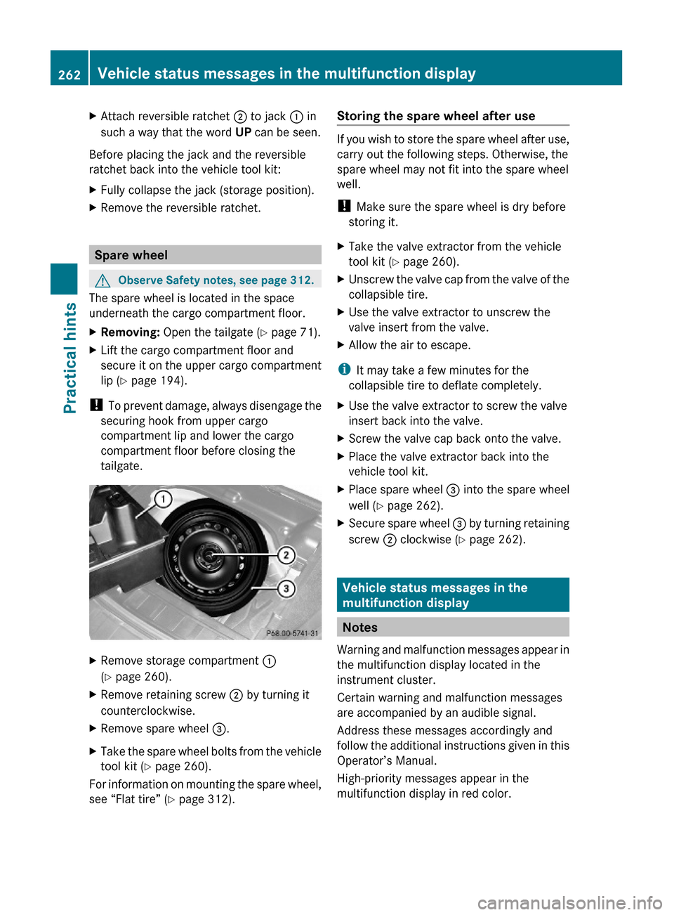
The spare wheel is located in the space
underneath the cargo compartment floor.
XRemoving: Open the tailgate (Y page 71).XLift the cargo compartment floor and
secure it on the upper cargo compartment
lip (Y page 194).
! To prevent damage, always disengage the
securing hook from upper cargo
compartment lip and lower the cargo
compartment floor before closing the
tailgate.
XRemove storage compartment :
(Y page 260).
XRemove retaining screw ; by turning it
counterclockwise.
XRemove spare wheel =.XTake the spare wheel bolts from the vehicle
tool kit (Y page 260).
For information on mounting the spare wheel,
see “Flat tire” (Y page 312).
Storing the spare wheel after use
If you wish to store the spare wheel after use,
carry out the following steps. Otherwise, the
spare wheel may not fit into the spare wheel
well.
! Make sure the spare wheel is dry before
storing it.
XTake the valve extractor from the vehicle
tool kit (Y page 260).
XUnscrew the valve cap from the valve of the
collapsible tire.
XUse the valve extractor to unscrew the
valve insert from the valve.
XAllow the air to escape.
iIt may take a few minutes for the
collapsible tire to deflate completely.
XUse the valve extractor to screw the valve
insert back into the valve.
XScrew the valve cap back onto the valve.XPlace the valve extractor back into the
vehicle tool kit.
XPlace spare wheel = into the spare wheel
well (Y page 262).
XSecure spare wheel = by turning retaining
screw ; clockwise (Y page 262).
Vehicle status messages in the
multifunction display
Notes
Warning and malfunction messages appear in
the multifunction display located in the
instrument cluster.
Certain warning and malfunction messages
are accompanied by an audible signal.
Address these messages accordingly and
follow the additional instructions given in this
Operator’s Manual.
High-priority messages appear in the
multifunction display in red color.
262Vehicle status messages in the multifunction displayPractical hints
X204_AKB; 3; 23, en-USd2ureepe,Version: 2.11.8.12009-07-16T19:16:58+02:00 - Seite 262
Page 279 of 344
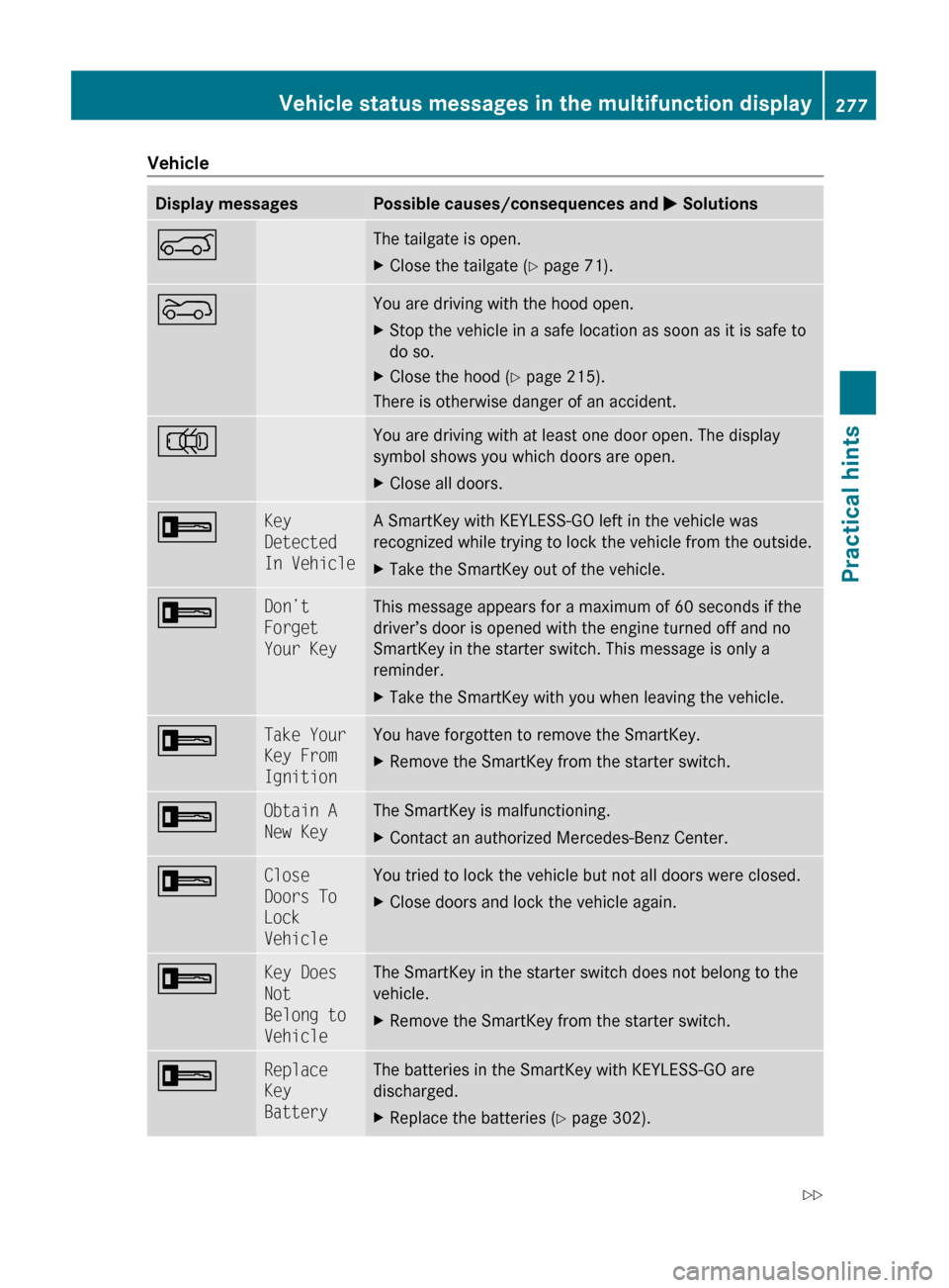
VehicleDisplay messagesPossible causes/consequences and M SolutionsAThe tailgate is open.XClose the tailgate ( Y page 71).?You are driving with the hood open.XStop the vehicle in a safe location as soon as it is safe to
do so.XClose the hood ( Y page 215).
There is otherwise danger of an accident.
;You are driving with at least one door open. The display
symbol shows you which doors are open.XClose all doors.+Key
Detected
In VehicleA SmartKey with KEYLESS-GO left in the vehicle was
recognized while trying to lock the vehicle from the outside.XTake the SmartKey out of the vehicle.+Don’t
Forget
Your KeyThis message appears for a maximum of 60 seconds if the
driver’s door is opened with the engine turned off and no
SmartKey in the starter switch. This message is only a
reminder.XTake the SmartKey with you when leaving the vehicle.+Take Your
Key From
IgnitionYou have forgotten to remove the SmartKey.XRemove the SmartKey from the starter switch.+Obtain A
New KeyThe SmartKey is malfunctioning.XContact an authorized Mercedes-Benz Center.+Close
Doors To
Lock
VehicleYou tried to lock the vehicle but not all doors were closed.XClose doors and lock the vehicle again.+Key Does
Not
Belong to
VehicleThe SmartKey in the starter switch does not belong to the
vehicle.XRemove the SmartKey from the starter switch.+Replace
Key
BatteryThe batteries in the SmartKey with KEYLESS-GO are
discharged.XReplace the batteries ( Y page 302).Vehicle status messages in the multifunction display277Practical hintsX204_AKB; 3; 23, en-USd2ureepe,Version: 2.11.8.12009-07-16T19:16:58+02:00 - Seite 277Z
Page 301 of 344
GWarning!
If the 45 indicator lamp does not
illuminate or remains out with the weight of a
typical 12-month-old child in a standard child
restraint or less on the front passenger seat,
do not transport a child on the front
passenger seat until the system has been
repaired.
Unlocking/locking manually
Unlocking the vehicle
If you cannot unlock the vehicle with the
SmartKey or with KEYLESS-GO, unlock the
driver’s door using the mechanical key.
The anti-theft alarm system will trigger when
you
Runlock the driver’s door with the
mechanical key
and
Ropen the driver’s door
To cancel the alarm, insert the SmartKey into
the starter switch.
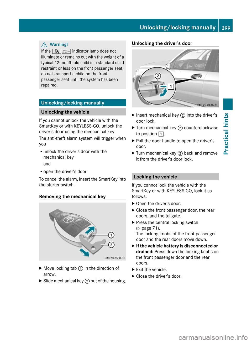
Removing the mechanical key
XMove locking tab : in the direction of
arrow.
XSlide mechanical key ; out of the housing.Unlocking the driver’s doorXInsert mechanical key ; into the driver’s
door lock.
XTurn mechanical key ; counterclockwise
to position 1.
XPull the door handle to open the driver’s
door.
XTurn mechanical key ; back and remove
it from the driver’s door lock.
Locking the vehicle
If you cannot lock the vehicle with the
SmartKey or with KEYLESS-GO, lock it as
follows:
XOpen the driver’s door.XClose the front passenger door, the rear
doors, and the tailgate.
XPress the central locking switch
(Y page 71).
The locking knobs of the front passenger
door and the rear doors move down.
XIf the vehicle battery is disconnected or
drained: Press down the locking knobs on
the front passenger door and the rear
doors.
XExit the vehicle.XClose the driver’s door.Unlocking/locking manually299Practical hintsX204_AKB; 3; 23, en-USd2ureepe,Version: 2.11.8.12009-07-16T19:16:58+02:00 - Seite 299Z
Page 302 of 344
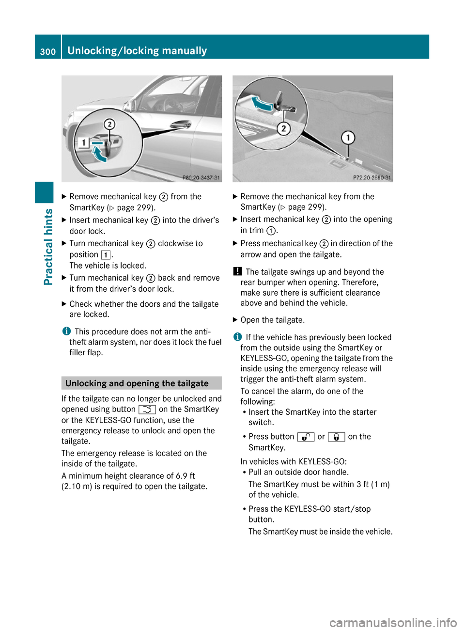
XRemove mechanical key ; from the
SmartKey (Y page 299).
XInsert mechanical key ; into the driver’s
door lock.
XTurn mechanical key ; clockwise to
position 1.
The vehicle is locked.
XTurn mechanical key ; back and remove
it from the driver’s door lock.
XCheck whether the doors and the tailgate
are locked.
iThis procedure does not arm the anti-
theft alarm system, nor does it lock the fuel
filler flap.
Unlocking and opening the tailgate
If the tailgate can no longer be unlocked and
opened using button F on the SmartKey
or the KEYLESS-GO function, use the
emergency release to unlock and open the
tailgate.
The emergency release is located on the
inside of the tailgate.
A minimum height clearance of 6.9 ft
(2.10 m) is required to open the tailgate.
XRemove the mechanical key from the
SmartKey (Y page 299).
XInsert mechanical key ; into the opening
in trim :.
XPress mechanical key ; in direction of the
arrow and open the tailgate.
! The tailgate swings up and beyond the
rear bumper when opening. Therefore,
make sure there is sufficient clearance
above and behind the vehicle.
XOpen the tailgate.
iIf the vehicle has previously been locked
from the outside using the SmartKey or
KEYLESS-GO, opening the tailgate from the
inside using the emergency release will
trigger the anti-theft alarm system.
To cancel the alarm, do one of the
following:RInsert the SmartKey into the starter
switch.
RPress button % or & on the
SmartKey.
In vehicles with KEYLESS-GO:RPull an outside door handle.
The SmartKey must be within 3 ft (1 m)
of the vehicle.
RPress the KEYLESS-GO start/stop
button.
The SmartKey must be inside the vehicle.
300Unlocking/locking manuallyPractical hints
X204_AKB; 3; 23, en-USd2ureepe,Version: 2.11.8.12009-07-16T19:16:58+02:00 - Seite 300
Page 303 of 344
Manually unlocking the gear selector
lever
If the vehicle’s electrical system is
malfunctioning, the gear selector lever could
remain locked in park position P. In this case
the gear selector lever can be unlocked
manually, e.g. to tow the vehicle.
XEngage the parking brake.
! Do not use sharp objects to loosen the
gear selector lever cover in the center
console, as this could damage the gear
selector lever cover or the center console.
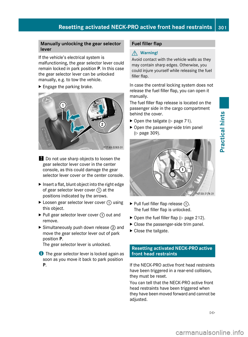
XInsert a flat, blunt object into the right edge
of gear selector lever cover : at the
positions indicated by the arrows.
XLoosen gear selector lever cover : using
this object.
XPull gear selector lever cover : out and
remove.
XSimultaneously push down release ; and
move the gear selector lever out of park
position P.
The gear selector lever is unlocked.
iThe gear selector lever is locked again as
soon as you move it back to park position
P.
Fuel filler flapGWarning!
Avoid contact with the vehicle walls as they
may contain sharp edges. Otherwise, you
could injure yourself while releasing the fuel
filler flap.
In case the central locking system does not
release the fuel filler flap, you can open it
manually.
The fuel filler flap release is located on the
passenger side in the cargo compartment
behind the cover.
XOpen the tailgate (Y page 71).XOpen the passenger-side trim panel
(Y page 309).
XPull fuel filler flap release :.
The fuel filler flap is unlocked.
XOpen the fuel filler flap (Y page 212).XClose the passenger-side trim panel.XClose the tailgate.
Resetting activated NECK-PRO active
front head restraints
If the NECK-PRO active front head restraints
have been triggered in a rear-end collision,
they must be reset.
You can tell that the NECK-PRO active front
head restraints have been triggered when
they have been moved forward and cannot be
adjusted.
Resetting activated NECK-PRO active front head restraints301Practical hintsX204_AKB; 3; 23, en-USd2ureepe,Version: 2.11.8.12009-07-16T19:16:58+02:00 - Seite 301Z
Page 310 of 344
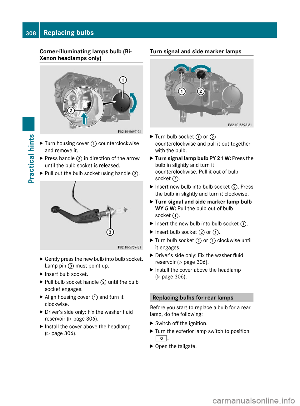
Corner-illuminating lamps bulb (Bi-
Xenon headlamps only)
XTurn housing cover : counterclockwise
and remove it.
XPress handle ; in direction of the arrow
until the bulb socket is released.
XPull out the bulb socket using handle ;.XGently press the new bulb into bulb socket.
Lamp pin = must point up.
XInsert bulb socket.XPull bulb socket handle ; until the bulb
socket engages.
XAlign housing cover : and turn it
clockwise.
XDriver’s side only: Fix the washer fluid
reservoir (Y page 306).
XInstall the cover above the headlamp
(Y page 306).
Turn signal and side marker lampsXTurn bulb socket : or ;
counterclockwise and pull it out together
with the bulb.
XTurn signal lamp bulb PY 21 W: Press the
bulb in slightly and turn it
counterclockwise. Pull it out of bulb
socket ;.
XInsert new bulb into bulb socket ;. Press
the bulb in slightly and turn it clockwise.
XTurn signal and side marker lamp bulb
WY 5 W: Pull the bulb out of bulb
socket :.
XInsert the new bulb into bulb socket :.XInsert bulb socket ; or :.XTurn bulb socket ; or : clockwise until
it engages.
XDriver’s side only: Fix the washer fluid
reservoir (Y page 306).
XInstall the cover above the headlamp
(Y page 306).
Replacing bulbs for rear lamps
Before you start to replace a bulb for a rear
lamp, do the following:
XSwitch off the ignition.XTurn the exterior lamp switch to position
$.
XOpen the tailgate.308Replacing bulbsPractical hints
X204_AKB; 3; 23, en-USd2ureepe,Version: 2.11.8.12009-07-16T19:16:58+02:00 - Seite 308