2010 MERCEDES-BENZ GL550 height
[x] Cancel search: heightPage 232 of 380
accident, for example. The hood could
otherwise come loose while the vehicle is in
motion and injure you and/or others.
XLet the hood drop from a height of
approximately 8 in (20 cm).
XCheck to make sure the hood is fully
closed.
If you can raise the hood at a point above
the headlamps, then it is not properly
closed. Open it again and let it drop with
somewhat greater force.
Radiator
iVehicles with diesel engine:
Do not cover the radiator, for example with
a winter front or bug cover. Otherwise the
readings of the on-board diagnostic system
may be inaccurate. Some of theses
readings are required by law and must be
accurate at all times.
Engine oil
The amount of oil your engine consumes will
depend on a number of factors, including
driving style. Increased oil consumption can
occur when the vehicle is new or the vehicle
is driven frequently at higher engine speeds.
Engine oil consumption checks should only
be made after the vehicle break-in period.
! Do not use any special lubricant additives,
as these may damage the drive assemblies.
Using special additives not approved by
Mercedes-Benz may cause damage not
covered by the Mercedes-Benz Limited
Warranty.
For further information contact an
authorized Mercedes-Benz Center.
Notes on checking engine oil level
When checking the oil level the vehicle must
be parked on level ground and the vehicle
must have been stationary for at least
5 minutes with the engine turned off.
Checking engine oil level
XOpen the hood (Y page 228).
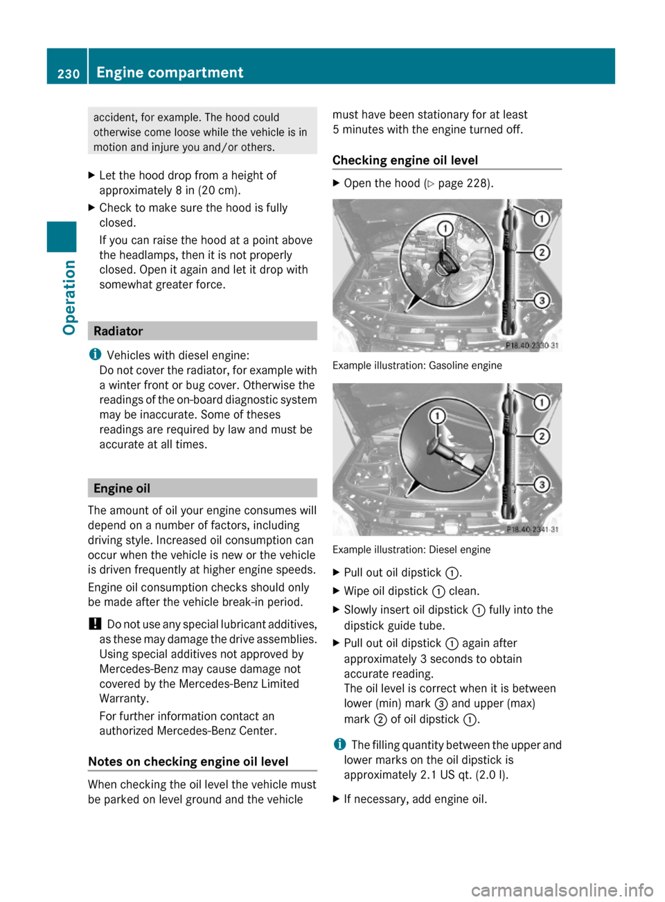
Example illustration: Gasoline engine
Example illustration: Diesel engine
XPull out oil dipstick :.XWipe oil dipstick : clean.XSlowly insert oil dipstick : fully into the
dipstick guide tube.
XPull out oil dipstick : again after
approximately 3 seconds to obtain
accurate reading.
The oil level is correct when it is between
lower (min) mark = and upper (max)
mark ; of oil dipstick :.
iThe filling quantity between the upper and
lower marks on the oil dipstick is
approximately 2.1 US qt. (2.0 l).
XIf necessary, add engine oil.230Engine compartmentOperation
X164_AKB; 5; 31, en-USd2ureepe,Version: 2.11.8.12009-09-11T12:30:16+02:00 - Seite 230
Page 253 of 380
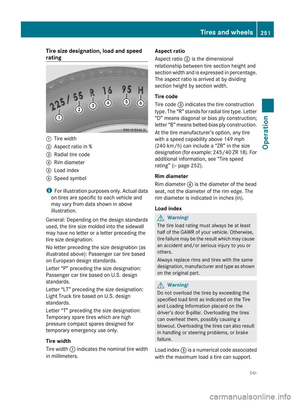
Tire size designation, load and speed
rating:Tire width;Aspect ratio in %=Radial tire code?Rim diameterALoad index BSpeed symbol
iFor illustration purposes only. Actual data
on tires are specific to each vehicle and
may vary from data shown in above
illustration.
General: Depending on the design standards
used, the tire size molded into the sidewall
may have no letter or a letter preceding the
tire size designation.
No letter preceding the size designation (as
illustrated above): Passenger car tire based
on European design standards.
Letter “P” preceding the size designation:
Passenger car tire based on U.S. design
standards.
Letter “LT” preceding the size designation:
Light Truck tire based on U.S. design
standards.
Letter “T” preceding the size designation:
Temporary spare tires which are high
pressure compact spares designed for
temporary emergency use only.
Tire width
Tire width : indicates the nominal tire width
in millimeters.
Aspect ratio
Aspect ratio ; is the dimensional
relationship between tire section height and
section width and is expressed in percentage.
The aspect ratio is arrived at by dividing
section height by section width.
Tire code
Tire code = indicates the tire construction
type. The “R” stands for radial tire type. Letter
“D” means diagonal or bias ply construction;
letter “B” means belted-bias ply construction.
At the tire manufacturer’s option, any tire
with a speed capability above 149 mph
(240 km/h) can include a “ZR” in the size
designation (for example: 245/40 ZR 18). For
additional information, see “Tire speed
rating” (Y page 252).
Rim diameter
Rim diameter ? is the diameter of the bead
seat, not the diameter of the rim edge. The
rim diameter is indicated in inches (in).
Load index
GWarning!
The tire load rating must always be at least
half of the GAWR of your vehicle. Otherwise,
tire failure may be the result which may cause
an accident and/or serious injury to you or
others.
Always replace rims and tires with the same
designation, manufacturer and type as shown
on the original part.
GWarning!
Do not overload the tires by exceeding the
specified load limit as indicated on the Tire
and Loading Information placard on the
driver’s door B-pillar. Overloading the tires
can overheat them, possibly causing a
blowout. Overloading the tires can also result
in handling or steering problems, or brake
failure.
Load index A is a numerical code associated
with the maximum load a tire can support.
Tires and wheels251OperationX164_AKB; 5; 31, en-USd2ureepe,Version: 2.11.8.12009-09-11T12:30:16+02:00 - Seite 251Z
Page 257 of 380
radio, and heater, to the extent that these
items are available as factory-installed
equipment (whether installed or not).
Air pressure
The amount of air inside the tire pressing
outward on each square inch of the tire. Air
pressure is expressed in pounds per square
inch (psi), kilopascal (kPa), or bar.
Aspect ratio
Dimensional relationship between tire
section height and section width expressed
in percentage.
Bar
Metric unit for air pressure. There are
14.5038 pounds per square inch (psi) to
1 bar; there are 100 kilopascals (kPa) to 1 bar.
Bead
The tire bead contains steel wires wrapped by
steel cords that hold the tire onto the rim.
Cold tire inflation pressure
Tire inflation pressure when your vehicle has
been sitting for at least 3 hours or driven no
more than 1 mile (1.6 km).
Curb weight
The weight of a motor vehicle with standard
equipment including the maximum capacity
of fuel, oil, and coolant, and, if so equipped,
air conditioning and additional optional
equipment, but without passengers and
cargo.
DOT (Department of Transportation)
A tire branding symbol which denotes the tire
meets requirements of the U.S. Department
of Transportation.
GAWR (Gross Axle Weight Rating)
The GAWR is the maximum permissible axle
weight. The gross vehicle weight on each axle
must never exceed the GAWR for the front
and rear axle indicated on the certification
label located on the driver’s door B-pillar.
GTW (Gross Trailer Weight)
The GTW is the weight of the trailer plus the
weight of all cargo, equipment, luggage etc.
loaded on the trailer.
GVW (Gross Vehicle Weight)
The GVW comprises the weight of the vehicle
including fuel, tools, spare wheel, installed
accessories, passengers and cargo and, if
applicable, trailer tongue load. The GVW must
never exceed the GVWR indicated on the
certification label located on the driver’s door
B-pillar.
GVWR (Gross Vehicle Weight Rating)
This is the maximum permissible vehicle
weight of the fully loaded vehicle (weight of
the vehicle including all options, passengers,
fuel, and cargo and, if applicable, trailer
tongue load). It is indicated on the
certification label located on the driver’s door
B-pillar.
Kilopascal (kPa)
Metric unit for air pressure. There are 6.9 kPa
to 1 psi; another metric unit for air pressure
is bar. There are 100 kilopascals (kPa) to
1 bar.
Load index
Numerical code associated with the
maximum load a tire can support.
Maximum load rating
The maximum load in kilograms and pounds
that can be carried by the tire.
Tires and wheels255OperationX164_AKB; 5; 31, en-USd2ureepe,Version: 2.11.8.12009-09-11T12:30:16+02:00 - Seite 255Z
Page 264 of 380
! Simultaneously depressing the
accelerator pedal and applying the brakes
reduces engine performance and causes
premature brake and drivetrain wear which
is not covered by the Mercedes-Benz
Limited Warranty.
Hydroplaning
Depending on the depth of the water layer on
the road, hydroplaning may occur, even at low
speeds and with new tires. In heavy rain or
when conditions indicate possible
hydroplaning:
XReduce vehicle speed.XAvoid track grooves in the road.XApply brakes cautiously.
Standing water
! Do not drive through flooded areas.
Before driving through water, determine its
depth.
If you must drive through standing water,
drive slowly to prevent water from entering
the passenger compartment or the engine
compartment. Water in these areas could
cause damage to electrical components or
wiring of the engine or transmission, or
could result in water being ingested by the
engine through the air intake causing
severe internal engine damage. Any such
damage is not covered by the Mercedes-
Benz Limited Warranty.
i Select the raised level ( Y page 159)
before driving through standing water.
For more information, see “Driving through
water” ( Y page 266).
Off-road drivingGWarning!
Do not load items on the crossbars. It may
cause instability during some maneuvers
which could result in an accident.
Drive slowly in unknown terrain. This will
make it easier to recognize unexpected
obstacles and avoid damage to the vehicle.
To help avoid the vehicle rolling over, never
turn it around on steep inclines. If the vehicle
cannot complete the attempted climb, back it
down in reverse gear.
Do not drive along the side of a slope. The
vehicle might otherwise rollover. If in doing so
the vehicle begins to show a tendency to roll,
immediately steer into a line of gravity
(straight up or downhill).
Never let the vehicle roll backwards in idle.
You may lose control of the vehicle if you use
only the service brake. For information on
driving downhill, see “Driving downhill”.
GWarning!
Sand, dirt, mud and other material having
friction property can cause exceptional wear
and tear as well as brake failure.
Have the brakes checked for dirt build-up and
cleaned. There is otherwise a risk that full
braking power may not be available in an
emergency.
GWarning!
Please be aware that by raising the vehicle
level, the center of gravity also rises.
Therefore, always ensure that the vehicle
level is as low as possible. With higher ride
height the ESP ®
may activate earlier in certain
situations.
Read this chapter carefully before you begin
off-road travel.
Familiarize yourself with the vehicle
characteristics and gear changing before you
attempt any difficult terrain off-road driving.
262Driving instructionsOperation
X164_AKB; 5; 31, en-USd2ureepe,Version: 2.11.8.12009-09-11T12:30:16+02:00 - Seite 262
Page 295 of 380
Display messagesPossible causes/consequences and M SolutionsFront
Passenger
Airbag
Disabled
See
Operator’s
ManualUSA only:
The front passenger front air bag is deactivated while driving
even though an adult or someone larger than a small
individual is occupying the front passenger seat. Forces
acting on the seat may make the system sense a decrease in
weight.XStop the vehicle in a safe location as soon as possible.XEngage the parking brake.XSwitch off the ignition.XHave the front passenger vacate the seat and exit the
vehicle.XAdjust the seat height to a higher position ( Y page 83).XMake sure no objects which apply forces to the seat are
present (e.g. objects such as books, briefcases etc. lodged
underneath, behind or around the seat). Such forces may
cause the system to sense that an occupant of a lesser
weight than actually present is on the front passenger seat.XKeep the seat unoccupied, close the front passenger door
and switch on the ignition.
Monitor the 42 indicator lamp in the center
console ( Y page 45) and the multifunction display in the
instrument cluster for the following:
With the seat unoccupied and the ignition switched on,
R the 42 indicator lamp in the center console
should illuminate and remain illuminated, indicating that
the OCS ( Y page 42) has deactivated the front passenger
front air bag.
R the message Front Passenger Airbag Enabled See
Operator’s Manual or the message Front Passenger
Airbag Disabled See Operator’s Manual should not
appear in the multifunction display at any time the seat is
unoccupied. Wait at least 60 seconds for the system to
complete the necessary check cycles and to make sure
neither message appears in the multifunction display.
If above conditions are met, you can occupy the front
passenger seat again. Depending on the front passenger
classification sensed by the OCS, the 42
indicator lamp will remain illuminated or go out.
If above conditions are not met, the system is not working
properly. Have the system checked at an authorized
Mercedes-Benz Center as soon as possible.
Vehicle status messages in the multifunction display293Practical hintsX164_AKB; 5; 31, en-USd2ureepe,Version: 2.11.8.12009-09-11T12:30:16+02:00 - Seite 293Z
Page 304 of 380

Display messagesPossible causes/consequences and M SolutionsÁCompressor
Cooling
DownYou have selected a higher vehicle level. Due to frequent level
changes within a short period, the compressor must cool
down first.
! When the message Compressor Cooling Down appears
in the multifunction display, driving is still possible. Keep in
mind that the ride height of the vehicle is not yet reached,
so you can damage the underbody of the vehicle.XLet the compressor cool down until the message
disappears.
The selected level will be set once the compressor has
cooled down.ÁRising
Max. 12
MPHThe vehicle is adjusting to off-road level 3.XDo not drive faster than 12 mph (20 km/h).ÁMax. 12
MPHYou are driving while using off-road level 3. The message
reminds you of the maximum speed at which you may drive
with off-road level 3.XDo not drive faster than 12 mph (20 km/h).ÆBeing
lowered
Max. 12
MPHThe vehicle is being lowered from off-road level 3 to off-road
level 2.XDo not drive faster than 12 mph
(20 km/h) until the off-road level 2 is reached.ÆReduce
speed to
under
12 MPHYou are driving too fast for the set vehicle level.GWarning!
Adapt your driving style to the modified driving conditions.
Avoid extreme, quick steering maneuvers. Please keep in
mind that the driving characteristics of the vehicle have been
modified. You should therefore drive in off-road level 3 with
particular caution as it could otherwise lead to an accident
and/or serious injury to you or others.
XDo not drive faster than 12 mph
(20 km/h) until the off-road level 2 is reached.8Locking
System
Inoperativ
e Service
RequiredThe differential locks are malfunctioning.XDo not drive faster than 50 mph (80 km/h).XHave the vehicle checked at an authorized Mercedes-Benz
Center.302Vehicle status messages in the multifunction displayPractical hints
X164_AKB; 5; 31, en-USd2ureepe,Version: 2.11.8.12009-09-11T12:30:16+02:00 - Seite 302
Page 335 of 380

XInsert a suitable object such as a coin into
the slot of lock :.
XTurn lock : by 90° in direction of the
arrow.
XRemove cover ;.
Replacing bulbs
Example illustration: LED rear lamp driver’s side
:Backup lamp bulb socket;Rear fog lamp bulb socket (driver’s side
only)
XDepending on which bulb needs to be
replaced, turn the respective bulb socket
counterclockwise.
XPull the bulb socket out of the housing.XBackup lamp bulb :: Gently press onto
the bulb and turn it counterclockwise out
of its bulb socket.
XGently press the new bulb into its bulb
socket and turn it clockwise until it
engages.
XRear fog lamp bulb ;: Pull the bulb out
of its bulb socket.
XGently press the new bulb into its bulb
socket.
XAlign the bulb socket and turn it clockwise.XMake sure the bulb socket is attached
properly.
XClose the respective cover in the cargo
compartment.
XClose the tailgate.License plate lampsXLoosen screws : of lamp cover to be
removed.
XRemove lamp cover ;.XReplace the bulb.XReinstall lamp cover ;.XRetighten screws :.
Adjusting headlamp aim
:V Vertical centerline;H Horizontal mounting height, measured
from the center
Replacing bulbs333Practical hintsX164_AKB; 5; 31, en-USd2ureepe,Version: 2.11.8.12009-09-11T12:30:16+02:00 - Seite 333Z
Page 343 of 380
Lifting the vehicleGWarning!
When jacking up the vehicle, only use the jack
which has been specifically approved by
Mercedes-Benz for your vehicle.
The jack is designed exclusively for jacking up
the vehicle at the jack take-up brackets built
into both sides of the vehicle. Make sure the
jack arm is fully seated in the jack take-up
bracket. The jack must always be vertical
when in use, especially on inclines or
declines.
The jack is intended only for lifting the vehicle
briefly for wheel changes. It is not suited for
performing maintenance work under the
vehicle. To help avoid personal injury, use the
jack only to lift the vehicle during a wheel
change.
Never get beneath the vehicle while it is
supported by the jack. Keep hands and feet
away from the area under the lifted vehicle.
Always lower the vehicle onto sufficient
capacity jackstands before working under the
vehicle.
Always engage the parking brake firmly and
block the wheels with wheel chocks or other
sizeable objects before raising the vehicle
with the jack. Do not disengage the parking
brake while the vehicle is raised.
Make sure that the ground on which the
vehicle is standing and where you place the
jack is solid, level and not slippery. If
necessary, use a large underlay. On slippery
surfaces, such as tiled floors, you should use
a non-slip underlay, for example a rubber mat.
Do not use wooden blocks or similar objects
to support the jack. Otherwise the jack may
not be able to achieve its load-bearing
capacity if it is not at its full height.
Never start the engine when the vehicle is
raised.
Also observe the notes on the jack.
XPrevent the vehicle from rolling away by
blocking wheels with wheel chocks or other
sizeable objects.
When your vehicle is equipped with a wheel
chock, it is included with the vehicle tool kit
(Y page 284). For information on setting up
the collapsible wheel chock, see
(Y page 286).
GWarning!
Only jack up the vehicle on level ground or on
slight inclines/declines. Otherwise, the
vehicle could fall off the jack and injure you or
others.
Changing a wheel on a level surface
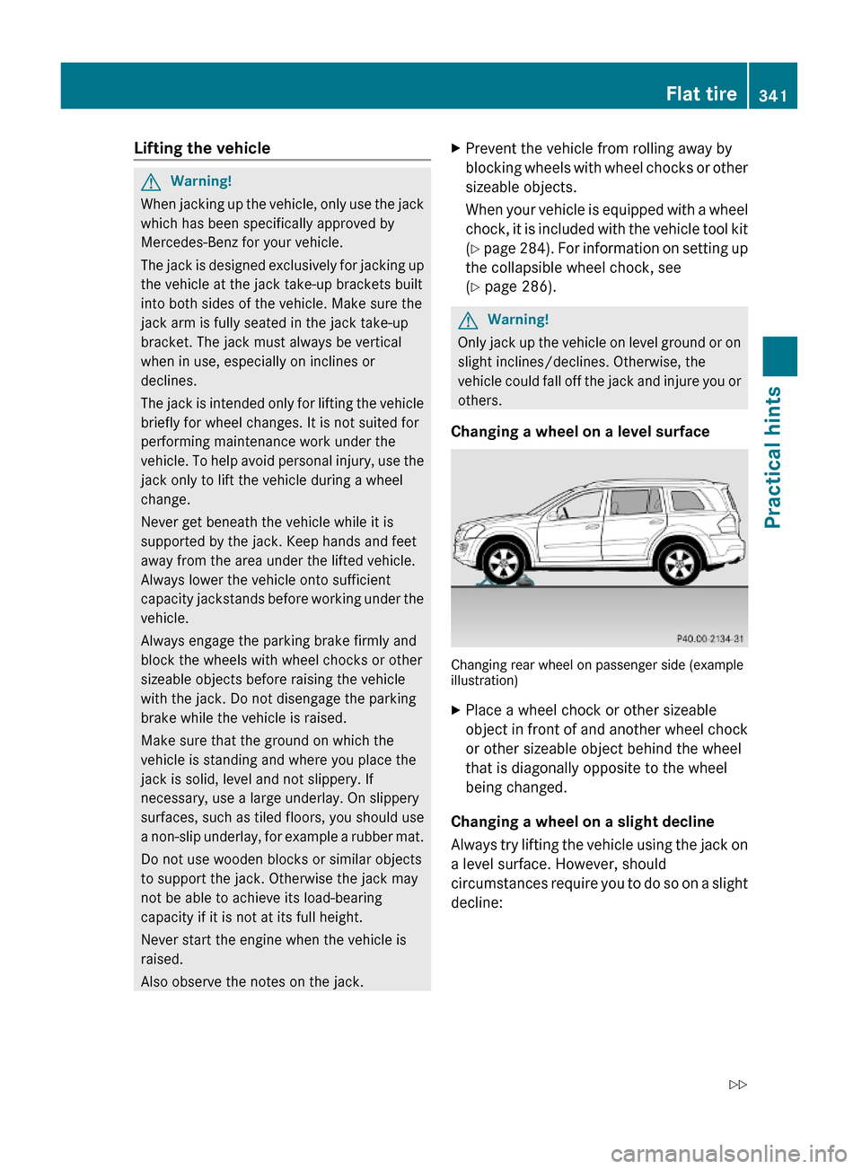
Changing rear wheel on passenger side (exampleillustration)
XPlace a wheel chock or other sizeable
object in front of and another wheel chock
or other sizeable object behind the wheel
that is diagonally opposite to the wheel
being changed.
Changing a wheel on a slight decline
Always try lifting the vehicle using the jack on
a level surface. However, should
circumstances require you to do so on a slight
decline:
Flat tire341Practical hintsX164_AKB; 5; 31, en-USd2ureepe,Version: 2.11.8.12009-09-11T12:30:16+02:00 - Seite 341Z