2010 MERCEDES-BENZ GL450 passenger
[x] Cancel search: passengerPage 327 of 380

In case the central locking system does not
release the fuel filler flap, you can open it
manually.
The fuel filler flap release is located on the
passenger side in the cargo compartment
behind the cover.
XOpen the tailgate (Y page 75).XOpen the cover on the passenger-side trim
panel (Y page 332).
XPull red fuel filler flap release : in
direction of arrow.
The fuel filler flap is unlocked.
XOpen the fuel filler flap (Y page 226).XClose the cover.XClose the tailgate.
Resetting activated NECK-PRO active
front head restraints
If the NECK-PRO active front head restraints
have been triggered in a rear-end collision,
they must be reset.
You can tell that the NECK-PRO active front
head restraints have been triggered when
they have been moved forward and cannot be
adjusted.
GWarning!
For safety reasons, have the NECK-PRO active
front head restraints checked at an
authorized Mercedes-Benz Center after a
rear-end collision.
GWarning!
When pushing back the head restraint
cushion, make sure your fingers do not
become caught between the head restraint
cushion and the cover. Failing to do so may
lead to injury.
iPressing the head restraint cushion back
requires high force. If you encounter
difficulties when pushing the head restraint
back, please have the procedure
performed at an authorized Mercedes-Benz
Center.
Head restraints (standard)
XPull the top of the head restraint cushion in
direction of arrow : as far as it will go.
XAdjust the head restraint cushion
downward in direction of arrow ; as far as
it will go.
XFirmly press the top of the head restraint
cushion towards the head restraint cover in
direction of arrow = until it engages.
XRepeat this procedure on the NECK-PRO
active front head restraint for the second
front seat.
Resetting activated NECK-PRO active front head restraints325Practical hintsX164_AKB; 5; 31, en-USd2ureepe,Version: 2.11.8.12009-09-11T12:30:16+02:00 - Seite 325Z
Page 334 of 380
XTurn housing cover ; counterclockwise
and remove it.
XTurn bulb socket C with the bulb
counterclockwise and remove it.
XPull the bulb out of bulb socket C.XGently press the new bulb into bulb socket
C.
XPlace bulb socket C back into the housing
and turn it clockwise until it engages.
XAlign housing cover ; and turn it
clockwise until it engages.
Parking and standing lamp bulb,
front turn signal lamp bulb,
side marker lamp bulb
XTurn respective bulb socket =, ? or A
(Y page 331) with the bulb
counterclockwise and remove it.
XPull the bulb out of the bulb socket.XGently press the new bulb into the bulb
socket.
XPlace bulb socket =, ? or A back into
the housing and turn it clockwise until it
engages.
Replacing bulbs for rear lamps
Before you start to replace a bulb for a rear
lamp, do the following:
XSwitch off the ignition.XTurn the exterior lamp switch to position
$.
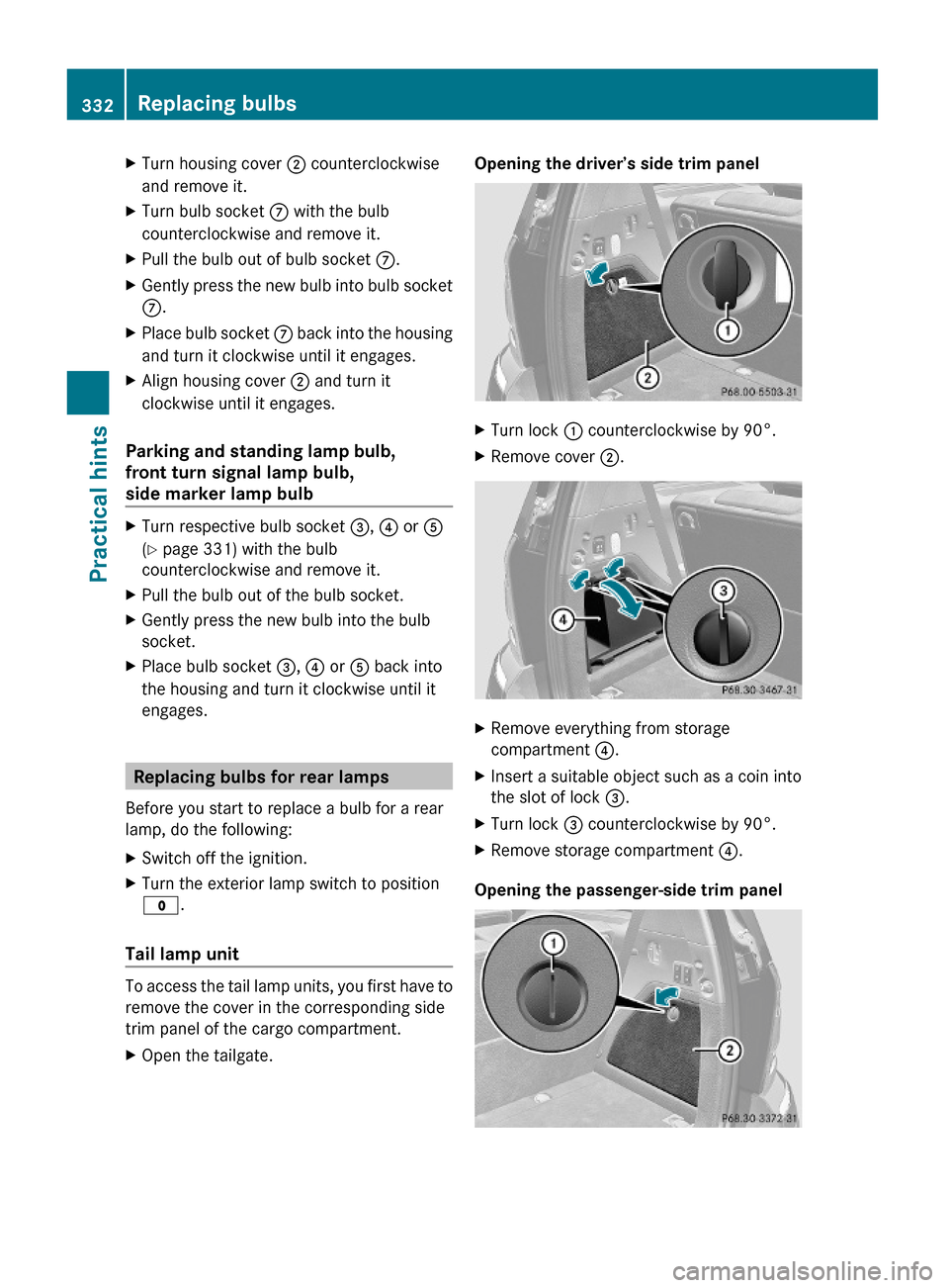
Tail lamp unit
To access the tail lamp units, you first have to
remove the cover in the corresponding side
trim panel of the cargo compartment.
XOpen the tailgate.Opening the driver’s side trim panelXTurn lock : counterclockwise by 90°.XRemove cover ;.XRemove everything from storage
compartment ?.
XInsert a suitable object such as a coin into
the slot of lock =.
XTurn lock = counterclockwise by 90°.XRemove storage compartment ?.
Opening the passenger-side trim panel
332Replacing bulbsPractical hints
X164_AKB; 5; 31, en-USd2ureepe,Version: 2.11.8.12009-09-11T12:30:16+02:00 - Seite 332
Page 339 of 380
Open doors only when conditions are safe
to do so.
XVehicles with KEYLESS-GO: Remove the
KEYLESS-GO start/stop button from the
starter switch.
XHave any passenger exit the vehicle at a
safe distance from the roadway. Open
doors only when conditions are safe to do
so.
iVehicles retrofitted with TIREFIT kit:
Only use the power outlet in the second-
row footwell for electric air pump
operation.
You can use the power outlet even when
the ignition is switched off, e.g. in order to
inflate the collapsible tire.
An emergency shut-off feature is designed
to prevent the vehicle’s on-board voltage
from dropping below a minimum level. If
the on-board voltage drops to this
minimum level, the power outlets are
switched off automatically to help preserve
engine starting power.
Sealing tires with TIREFIT
This section applies to vehicles retrofitted
with a TIREFIT kit only.
Small tire punctures, particularly those in the
tread, can be sealed with TIREFIT.
TIREFIT can be used in ambient temperatures
down to -4‡ (-20†).
GWarning!
TIREFIT is a limited repair device. TIREFIT
cannot be used for cuts or punctures larger
than approximately 0.16 in (4 mm) and tire
damage caused by driving with extremely low
tire inflation pressure, or on a flat tire, or a
damaged wheel.
Do not drive the vehicle under such
circumstances.
Contact the nearest authorized Mercedes-
Benz Center for assistance or call Roadside
Assistance.
XForeign objects (e.g. screws or nails)
should not be removed from the tire.
XTake the TIREFIT kit, the sticker, and the
electric air pump out of the vehicle.
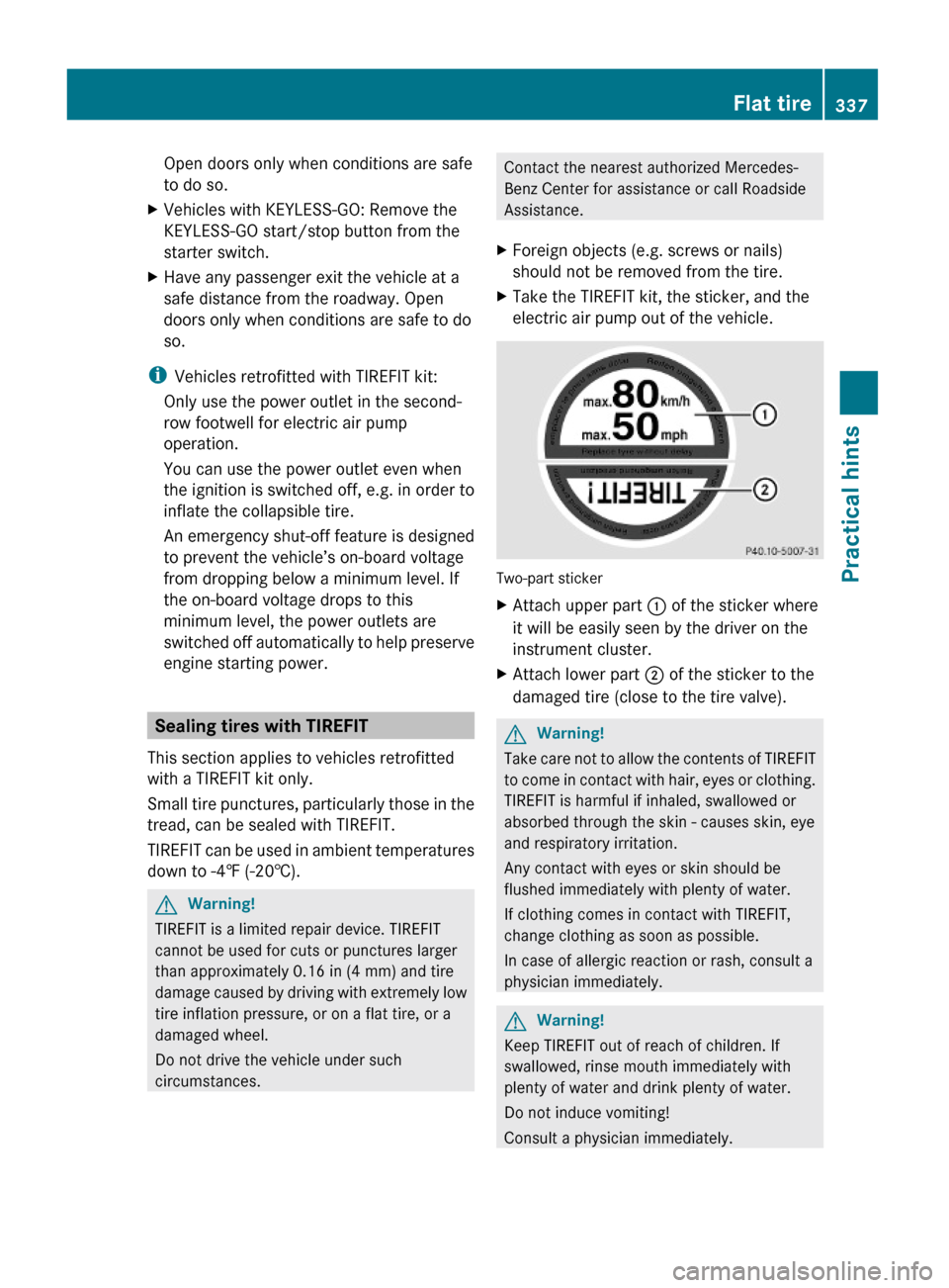
Two-part sticker
XAttach upper part : of the sticker where
it will be easily seen by the driver on the
instrument cluster.
XAttach lower part ; of the sticker to the
damaged tire (close to the tire valve).
GWarning!
Take care not to allow the contents of TIREFIT
to come in contact with hair, eyes or clothing.
TIREFIT is harmful if inhaled, swallowed or
absorbed through the skin - causes skin, eye
and respiratory irritation.
Any contact with eyes or skin should be
flushed immediately with plenty of water.
If clothing comes in contact with TIREFIT,
change clothing as soon as possible.
In case of allergic reaction or rash, consult a
physician immediately.
GWarning!
Keep TIREFIT out of reach of children. If
swallowed, rinse mouth immediately with
plenty of water and drink plenty of water.
Do not induce vomiting!
Consult a physician immediately.
Flat tire337Practical hintsX164_AKB; 5; 31, en-USd2ureepe,Version: 2.11.8.12009-09-11T12:30:16+02:00 - Seite 337Z
Page 340 of 380
iIf sealant has leaked out, let it dry. You
can then peel it off.
If clothing has come in contact with
TIREFIT, have it dry-cleaned with
perchloroethylene as soon as possible.
GWarning!
Observe safety instructions on air pump label.
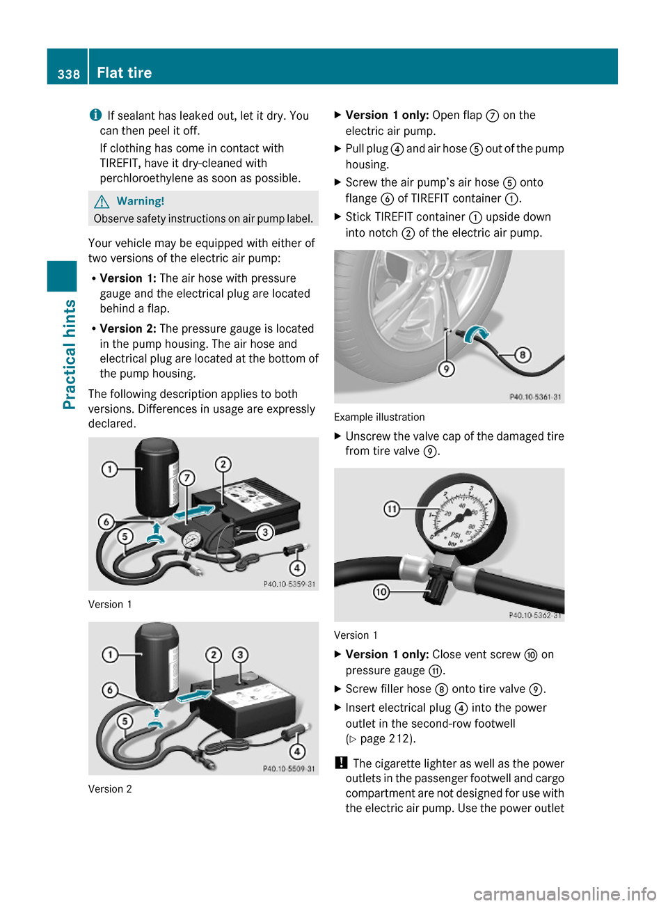
Your vehicle may be equipped with either of
two versions of the electric air pump:
RVersion 1: The air hose with pressure
gauge and the electrical plug are located
behind a flap.
RVersion 2: The pressure gauge is located
in the pump housing. The air hose and
electrical plug are located at the bottom of
the pump housing.
The following description applies to both
versions. Differences in usage are expressly
declared.
Version 1
Version 2
XVersion 1 only: Open flap C on the
electric air pump.
XPull plug ? and air hose A out of the pump
housing.
XScrew the air pump’s air hose A onto
flange B of TIREFIT container :.
XStick TIREFIT container : upside down
into notch ; of the electric air pump.
Example illustration
XUnscrew the valve cap of the damaged tire
from tire valve E.
Version 1
XVersion 1 only: Close vent screw F on
pressure gauge G.
XScrew filler hose D onto tire valve E.XInsert electrical plug ? into the power
outlet in the second-row footwell
(Y page 212).
! The cigarette lighter as well as the power
outlets in the passenger footwell and cargo
compartment are not designed for use with
the electric air pump. Use the power outlet
338Flat tirePractical hints
X164_AKB; 5; 31, en-USd2ureepe,Version: 2.11.8.12009-09-11T12:30:16+02:00 - Seite 338
Page 343 of 380
Lifting the vehicleGWarning!
When jacking up the vehicle, only use the jack
which has been specifically approved by
Mercedes-Benz for your vehicle.
The jack is designed exclusively for jacking up
the vehicle at the jack take-up brackets built
into both sides of the vehicle. Make sure the
jack arm is fully seated in the jack take-up
bracket. The jack must always be vertical
when in use, especially on inclines or
declines.
The jack is intended only for lifting the vehicle
briefly for wheel changes. It is not suited for
performing maintenance work under the
vehicle. To help avoid personal injury, use the
jack only to lift the vehicle during a wheel
change.
Never get beneath the vehicle while it is
supported by the jack. Keep hands and feet
away from the area under the lifted vehicle.
Always lower the vehicle onto sufficient
capacity jackstands before working under the
vehicle.
Always engage the parking brake firmly and
block the wheels with wheel chocks or other
sizeable objects before raising the vehicle
with the jack. Do not disengage the parking
brake while the vehicle is raised.
Make sure that the ground on which the
vehicle is standing and where you place the
jack is solid, level and not slippery. If
necessary, use a large underlay. On slippery
surfaces, such as tiled floors, you should use
a non-slip underlay, for example a rubber mat.
Do not use wooden blocks or similar objects
to support the jack. Otherwise the jack may
not be able to achieve its load-bearing
capacity if it is not at its full height.
Never start the engine when the vehicle is
raised.
Also observe the notes on the jack.
XPrevent the vehicle from rolling away by
blocking wheels with wheel chocks or other
sizeable objects.
When your vehicle is equipped with a wheel
chock, it is included with the vehicle tool kit
(Y page 284). For information on setting up
the collapsible wheel chock, see
(Y page 286).
GWarning!
Only jack up the vehicle on level ground or on
slight inclines/declines. Otherwise, the
vehicle could fall off the jack and injure you or
others.
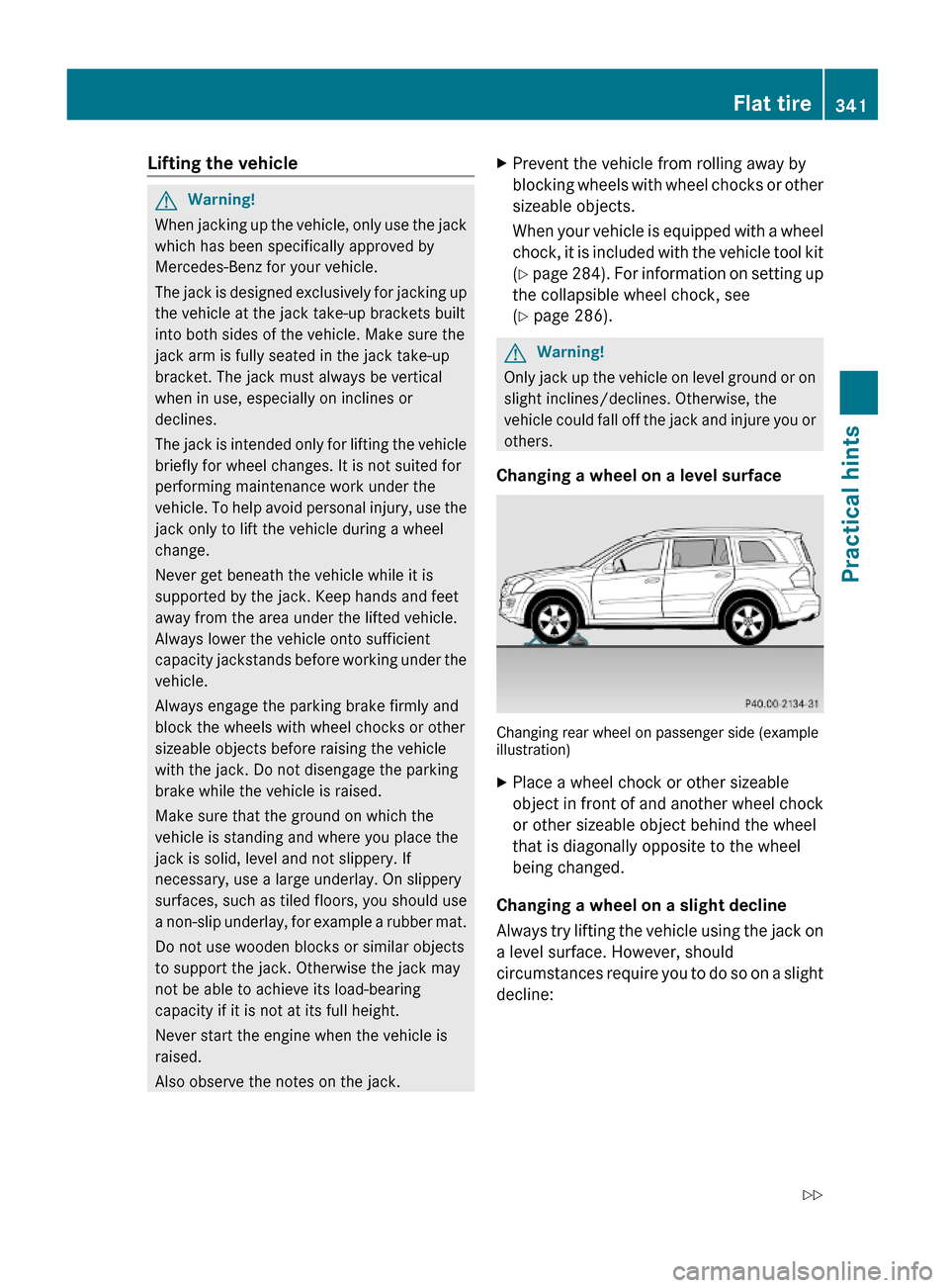
Changing a wheel on a level surface
Changing rear wheel on passenger side (exampleillustration)
XPlace a wheel chock or other sizeable
object in front of and another wheel chock
or other sizeable object behind the wheel
that is diagonally opposite to the wheel
being changed.
Changing a wheel on a slight decline
Always try lifting the vehicle using the jack on
a level surface. However, should
circumstances require you to do so on a slight
decline:
Flat tire341Practical hintsX164_AKB; 5; 31, en-USd2ureepe,Version: 2.11.8.12009-09-11T12:30:16+02:00 - Seite 341Z
Page 344 of 380
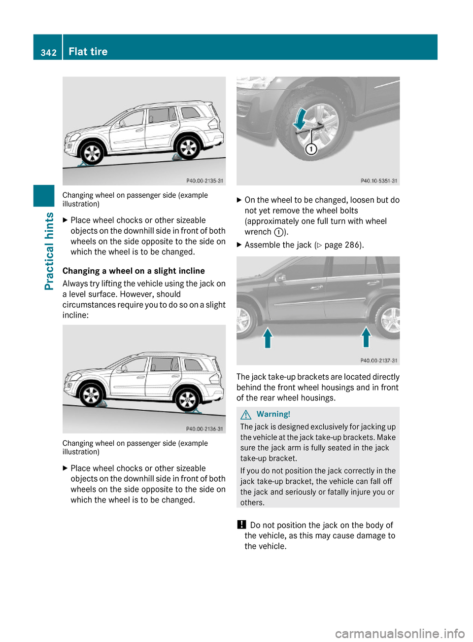
Changing wheel on passenger side (exampleillustration)
XPlace wheel chocks or other sizeable
objects on the downhill side in front of both
wheels on the side opposite to the side on
which the wheel is to be changed.
Changing a wheel on a slight incline
Always try lifting the vehicle using the jack on
a level surface. However, should
circumstances require you to do so on a slight
incline:
Changing wheel on passenger side (exampleillustration)
XPlace wheel chocks or other sizeable
objects on the downhill side in front of both
wheels on the side opposite to the side on
which the wheel is to be changed.
XOn the wheel to be changed, loosen but do
not yet remove the wheel bolts
(approximately one full turn with wheel
wrench :).
XAssemble the jack (Y page 286).
The jack take-up brackets are located directly
behind the front wheel housings and in front
of the rear wheel housings.
GWarning!
The jack is designed exclusively for jacking up
the vehicle at the jack take-up brackets. Make
sure the jack arm is fully seated in the jack
take-up bracket.
If you do not position the jack correctly in the
jack take-up bracket, the vehicle can fall off
the jack and seriously or fatally injure you or
others.
! Do not position the jack on the body of
the vehicle, as this may cause damage to
the vehicle.
342Flat tirePractical hints
X164_AKB; 5; 31, en-USd2ureepe,Version: 2.11.8.12009-09-11T12:30:16+02:00 - Seite 342
Page 353 of 380
Never lean over batteries while connecting or
jump starting. You might get injured.
Battery fluid contains sulfuric acid. Do not
allow this fluid to come in contact with eyes,
skin or clothing. In case it does, immediately
flush affected area with water, and seek
medical help if necessary.
A battery will also produce hydrogen gas,
which is flammable and explosive. Keep
flames or sparks away from battery, avoid
improper connection of jumper cables,
smoking, etc.
Attempting to jump start a frozen battery can
result in it exploding, causing personal injury.
Read all instructions before proceeding.
! Do not tow-start the vehicle. You could
otherwise seriously damage the automatic
transmission which is not covered by the
Mercedes-Benz Limited Warranty.
! Jump starting should only be performed
using the jump-start terminals located in
the engine compartment.
Avoid repeated and lengthy starting
attempts.
Do not attempt to start the engine using a
battery quick-charge unit.
If the engine does not run after several
unsuccessful starting attempts, have it
checked at the nearest authorized
Mercedes-Benz Center.
Excessive unburned fuel generated by
repeated failed starting attempts may
damage the catalytic converter 20
and may
present a fire risk.
Make sure the jumper cables do not have
loose or missing insulation.
Make sure the cable clamps do not touch
any other metal part while the other end is
still attached to a battery.If the battery is discharged, the engine can be
started with jumper cables and the fully
charged battery of another vehicle or an
equivalent starter pack. Observe the
following:
R Access to the battery is not possible on all
vehicles. If you cannot access the battery
of the other vehicle, provide jump start
power by an external battery or starter
pack.
R Jump starting should only be performed
when the engine and catalytic converter 21
are cold.
R Do not start the engine if the battery is
frozen. Let the battery thaw out first.
R Only jump start from batteries with the
same voltage rating (12 V). Jump starting
with a more powerful battery could damage
the vehicle’s electrical system. Such
damage will not be covered by the
Mercedes-Benz Limited Warranty.
R Only use jumper cables with sufficient
cross-section and insulated terminal
clamps.
R Always make sure the jumper cables are
not on or near pulleys, fans or other parts
that move when an engine is started or
running.
R Should the battery be drained completely,
let the donating power source charge the
vehicle for several minutes before
reattempting the starting process.
The jump-start contacts are located in the
engine compartment on the passenger side.XMake sure the two vehicles do not touch.XSwitch off all electrical consumers.XEngage the parking brake.XMake sure the automatic transmission is in
park position P.XOpen the hood ( Y page 228).20
Vehicles with gasoline engine only.
21 Vehicles with gasoline engine only.Jump starting351Practical hintsX164_AKB; 5; 31, en-USd2ureepe,Version: 2.11.8.12009-09-11T12:30:16+02:00 - Seite 351Z
Page 358 of 380

XTurn off the engine.XRemove the SmartKey from the starter
switch.
XVehicles with KEYLESS-GO: Open the
driver’s door (this puts the starter switch in
position 0, same as with the SmartKey
removed from the starter switch). The
driver’s door then can be closed again.
Fuse box in passenger compartment
! Do not use sharp objects such as a
screwdriver to open the fuse box cover in
the dashboard. You could damage the fuse
box cover or the dashboard.
The fuse box is located behind a cover in the
dashboard on the front passenger side.
XOpen the front passenger door.XOpening: Open the glove box.XOpening: Insert flat, blunt object as a lever
into the edge of fuse box cover : at the
position indicated by the arrow.
XLoosen fuse box cover : from the
dashboard using the lever.
XUsing your hands, pull fuse box cover :
out and remove.
XClosing: Hook fuse box cover : into
holders on the front of the dashboard.
XPress fuse box cover : back on until it
engages.
! The fuse box cover must be properly
positioned as described. Otherwise,
moisture or dirt could enter the fuse box
and possibly impair fuse operation.
Fuse box in engine compartment
XOpen the hood.
Example illustration fuse box GL 450 (GL 350BlueTEC, GL 550 similar)
XWith a dry cloth, remove any moisture from
fuse box cover :.
XOpening: Pull clamps ; in direction of
arrow.
XLift fuse box cover : up.XClosing: Make sure the sealing rubber is
positioned properly.
XPress fuse box cover : down and secure
with clamps ;.
! The fuse box cover must be properly
positioned as described. Otherwise,
moisture or dirt could enter the fuse box
and possibly impair fuse operation.
XClose the hood after checking or replacing
fuses.
356FusesPractical hints
X164_AKB; 5; 31, en-USd2ureepe,Version: 2.11.8.12009-09-11T12:30:16+02:00 - Seite 356