2010 MERCEDES-BENZ E350 ECU
[x] Cancel search: ECUPage 272 of 372
XRemoving vehicle tool kit box: Pull
tab : in direction of arrow ; and lift
vehicle tool kit box D.
XRemove vehicle tool kit box D from
luggage bowl E.
XOpening vehicle tool kit box cover: Pull
tab B in direction of arrow A and open
vehicle tool kit box cover =.
XClosing vehicle tool kit box cover: Push
vehicle tool kit box cover = downward
until it engages into vehicle tool kit box
D.
XInstalling vehicle tool kit box: Slide
vehicle tool kit box D into the recess of
luggage bowl E.
XPush vehicle tool kit box D downward until
it engages into luggage bowl E.
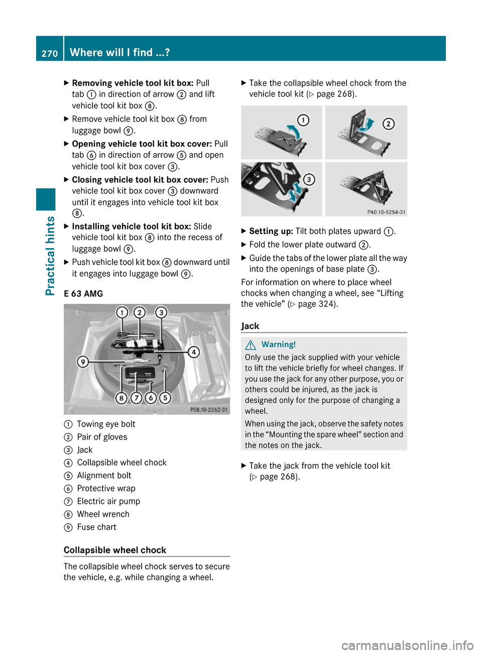
E 63 AMG
:Towing eye bolt;Pair of gloves=Jack?Collapsible wheel chockAAlignment boltBProtective wrapCElectric air pumpDWheel wrenchEFuse chart
Collapsible wheel chock
The collapsible wheel chock serves to secure
the vehicle, e.g. while changing a wheel.
XTake the collapsible wheel chock from the
vehicle tool kit (Y page 268).
XSetting up: Tilt both plates upward :.XFold the lower plate outward ;.XGuide the tabs of the lower plate all the way
into the openings of base plate =.
For information on where to place wheel
chocks when changing a wheel, see “Lifting
the vehicle” (Y page 324).
Jack
GWarning!
Only use the jack supplied with your vehicle
to lift the vehicle briefly for wheel changes. If
you use the jack for any other purpose, you or
others could be injured, as the jack is
designed only for the purpose of changing a
wheel.
When using the jack, observe the safety notes
in the “Mounting the spare wheel” section and
the notes on the jack.
XTake the jack from the vehicle tool kit
(Y page 268).
270Where will I find ...?Practical hints
212_AKB; 2; 41, en-USd2ureepe,Version: 2.11.8.12009-07-17T09:14:21+02:00 - Seite 270
Page 273 of 372
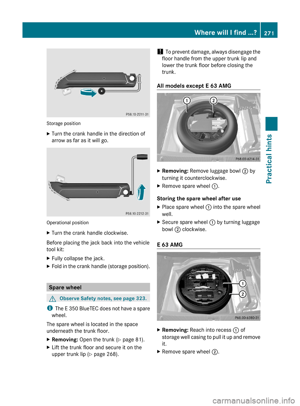
Storage position
XTurn the crank handle in the direction of
arrow as far as it will go.
Operational position
XTurn the crank handle clockwise.
Before placing the jack back into the vehicle
tool kit:
XFully collapse the jack.XFold in the crank handle (storage position).
Spare wheel
GObserve Safety notes, see page 323.
iThe E 350 BlueTEC does not have a spare
wheel.
The spare wheel is located in the space
underneath the trunk floor.
XRemoving: Open the trunk (Y page 81).XLift the trunk floor and secure it on the
upper trunk lip (Y page 268).
! To prevent damage, always disengage the
floor handle from the upper trunk lip and
lower the trunk floor before closing the
trunk.
All models except E 63 AMG
XRemoving: Remove luggage bowl ; by
turning it counterclockwise.
XRemove spare wheel :.
Storing the spare wheel after use
XPlace spare wheel : into the spare wheel
well.
XSecure spare wheel : by turning luggage
bowl ; clockwise.
E 63 AMG
XRemoving: Reach into recess : of
storage well casing to pull it up and remove
it.
XRemove spare wheel ;.Where will I find ...?271Practical hints212_AKB; 2; 41, en-USd2ureepe,Version: 2.11.8.12009-07-17T09:14:21+02:00 - Seite 271Z
Page 278 of 372
Display messagesPossible causes/consequences and M SolutionsFront
Passenger
Airbag
Enabled
See
Operator’s
ManualUSA only:
The front passenger front air bag is activated while driving
even though a child, small individual, or object below the
system’s weight threshold is on the front passenger seat, or
the front passenger seat is empty. Objects on the seat or
forces acting on the seat may make the system sense
supplemental weight.XStop the vehicle in a safe location as soon as possible.XEngage the parking brake.XSwitch off the ignition.XOpen the front passenger door.XRemove child and child restraint from front passenger seat
and properly secure the child in rear seat employing the
child restraint if necessary.XMake sure no objects which apply supplemental weight to
the seat are present. The system may recognize such
supplemental weight and sense that an occupant on the
front passenger seat is of a greater weight than actually
present.XKeep the seat unoccupied, close the front passenger door
and switch on the ignition.
Monitor the 45 indicator lamp in the center console
( Y page 45) and the multifunction display in the instrument
cluster ( Y page 28) for the following:
With the seat unoccupied and the ignition switched on,
R the 45 indicator lamp in the center console should
illuminate and remain illuminated, indicating that the OCS
( Y page 43) has deactivated the front passenger front air
bag.
R the message Front Passenger Airbag Enabled See
Operator’s Manual or the message Front Passenger
Airbag Disabled See Operator’s Manual should not
appear in the multifunction display at any time the seat is
unoccupied. Wait at least 60 seconds for the system to
complete the necessary check cycles and to make sure
neither message appears in the multifunction display.
If above conditions are met, you can occupy the front
passenger seat again. Depending on the front passenger
classification sensed by the OCS, the 45 indicator
lamp will remain illuminated or go out.
276Vehicle status messages in the multifunction displayPractical hints
212_AKB; 2; 41, en-USd2ureepe,Version: 2.11.8.12009-07-17T09:14:21+02:00 - Seite 276
Page 339 of 372
flush affected area with water and seek
medical help if necessary.
A battery will also produce hydrogen gas,
which is flammable and explosive. Keep
flames or sparks away from battery, avoid
improper connection of jumper cables,
smoking etc.GWarning!
Do not place metal objects on the battery as
this could result in a short circuit.
Use leak-proof batteries only to avoid the risk
of acid burns in the event of an accident.
Take care that you do not become statically
charged, e.g. by wearing synthetic clothing or
rubbing against textiles. For this reason, you
also should not pull or push the battery over
carpets or other synthetic materials.
Never touch the battery first. First touch the
outside body of the vehicle in order to release
any possible electrostatic charges.
Do not rub the battery with rags or cloths. The
battery could explode if touched due to
electrostatic charge or due to spark
formation.
! The battery is a
Valve-Regulated Lead
Acid (VRLA) battery, also referred to as
“fleece” battery.
Such batteries do not require topping-up of
the electrolyte level. VRLA batteries
therefore do not have cell caps and the
battery cover is non-removable. Do not
attempt to open the battery as otherwise
the battery will be damaged.
VRLA batteries do not require topping-up of
the electrolyte level. They cannot be
opened to check the electrolyte level.
However, the battery condition must be
checked periodically by performing a
battery conductance test. Refer to
Maintenance Booklet for battery condition
testing intervals.
The factory-equipped battery may only be
replaced with a battery that
R has the same security features
R is of identical size
R is of identical voltage
R is of identical capacity
! As any other battery, the battery may
discharge if you do not operate the vehicle
for an extended period of time. Have the
battery disconnected at a qualified
workshop or an authorized Mercedes-Benz
Center in such a case. You may also
connect an accessory battery charge unit
expressly approved by Mercedes-Benz for
your vehicle model to maintain the battery
charge. Contact an authorized Mercedes-
Benz Center for further information.
The battery, the battery ventilation hose
and the lateral plug must always be
securely installed when the vehicle is in
operation.
! Never loosen or detach battery terminal
clamps while the engine is running or the
SmartKey is in the starter switch or
KEYLESS-GO button is in position 1.
Otherwise the alternator and other
electronic components could be severely
damaged.
Have the battery checked regularly at an
authorized Mercedes-Benz Center.
Refer to Maintenance Booklet for
maintenance intervals or contact an
authorized Mercedes-Benz Center for
further information.
Charging the battery
GWarning!
Never charge a battery while still installed in
the vehicle unless the accessory battery
charge unit approved by Mercedes-Benz is
being used. Gases may escape during
Battery337Practical hints212_AKB; 2; 41, en-USd2ureepe,Version: 2.11.8.12009-07-17T09:14:21+02:00 - Seite 337Z
Page 345 of 372

iWhile being towed with the hazard
warning flasher in use, use the combination
switch in the usual manner to signal turns.
Only the selected turn signal will operate.
Upon canceling the turn signal, the hazard
warning flasher will operate again.
Fuses
Introduction
The electrical fuses in your vehicle serve to
switch off malfunctioning power circuits.
If a fuse is blown, the components and
systems secured by that fuse will stop
operating.
GWarning!
Only use fuses approved by Mercedes-Benz
with the specified amperage for the system in
question and do not attempt to repair or
bridge a blown fuse. Using other than
approved fuses or using repaired or bridged
fuses may cause an overload leading to a fire,
and/or cause damage to electrical
components and/or systems. Have the cause
determined and remedied by an authorized
Mercedes-Benz Center.
A blown fuse must be replaced by an
appropriate spare fuse (recognizable by its
color or the fuse rating given on the fuse) of
the amperage recommended in the fuse
chart. Any Mercedes-Benz Center will be glad
to advise you on this subject.
iIn case of a blown fuse contact Roadside
Assistance or an authorized Mercedes-
Benz Center.
If a newly inserted fuse blows again, have the
cause determined and rectified by an
authorized Mercedes-Benz Center.
The fuse chart is located in the trunk with the
vehicle tool kit (Y page 268). The fuse chart
explains the fuse allocation and fuse
amperages.
Before replacing fusesXEngage the parking brake.XMake sure the automatic transmission is in
park position P.
The transmission position indicator in the
multifunction display should be on P.
XSwitch off all electrical consumers.XTurn off the engine.XRemove the SmartKey from the starter
switch.
XVehicles with KEYLESS-GO: Open the
driver’s door (this puts the starter switch in
position 0, same as with the SmartKey
removed from the starter switch). The
driver’s door then can be closed again.
Fuse box in trunk
XOpen the trunk.XOpening: Insert flat, blunt object as a lever
into the upper edge of cover : and pull
cover : downward in direction of arrow.
XClosing: Install cover :.
Fuse box in engine compartment
XOpen the hood.Fuses343Practical hints212_AKB; 2; 41, en-USd2ureepe,Version: 2.11.8.12009-07-17T09:14:21+02:00 - Seite 343Z
Page 346 of 372
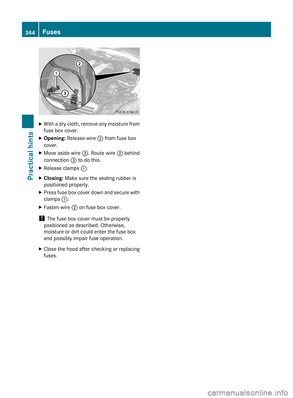
XWith a dry cloth, remove any moisture from
fuse box cover.
XOpening: Release wire ; from fuse box
cover.
XMove aside wire ;. Route wire ; behind
connection = to do this.
XRelease clamps :.XClosing: Make sure the sealing rubber is
positioned properly.
XPress fuse box cover down and secure with
clamps :.
XFasten wire ; on fuse box cover.
! The fuse box cover must be properly
positioned as described. Otherwise,
moisture or dirt could enter the fuse box
and possibly impair fuse operation.
XClose the hood after checking or replacing
fuses.
344FusesPractical hints
212_AKB; 2; 41, en-USd2ureepe,Version: 2.11.8.12009-07-17T09:14:21+02:00 - Seite 344