2010 MERCEDES-BENZ CLS63AMG weight
[x] Cancel search: weightPage 209 of 308
Maximum permissible tire inflation
pressure
This number is the greatest amount of air
pressure that should ever be put in the tire.
Normal occupant weight
The number of occupants the vehicle is
designed to seat, multiplied by 68 kilograms
(150 lb).
Occupant distribution
The distribution of occupants in a vehicle at
their designated seating positions.
Production options weight
The combined weight of those installed
regular production options weighing over
5 lbs (2.3 kilograms) in excess of those
standard items which they replace, not
previously considered in curb weight or
accessory weight, including heavy duty
brakes, ride levelers, roof rack, heavy duty
battery, and special trim.
PSI (Pounds per square inch)
A standard unit of measure for air pressure.
Recommended tire inflation pressure
The recommended tire inflation pressure for
normal
driving conditions is listed on the Tire
and Loading Information placard located on
the driver’s door B-pillar. It provides best
handling, tread life and riding comfort.
Supplemental information pertaining to
special driving situations can be found on the
tire inflation pressure label on the inside of
the fuel filler flap.
Rim A metal support for a tire or a tire and tube
assembly upon which the tire beads are
seated. Sidewall The portion of a tire between the tread and
the bead.
TIN (Tire Identification Number)
Unique identifier which facilitates efforts by
tire manufacturers to notify purchasers in
recall situations or other safety matters
concerning tires and gives purchasers the
means
to easily identify such tires. The TIN is
comprised of “Manufacturer’s identification
mark”, “Tire size”, “Tire type code” and “Date
of manufacture”.
Tire ply composition and material used This indicates the number of plies or the
number of layers of rubber-coated fabric in
the tire tread and sidewall. Tire
manufacturers also must indicate the ply
materials in the tire and sidewall, which
include steel, nylon, polyester, and others.
Tire speed rating
Part of tire designation (speed symbol);
indicates the speed range for which a tire is
approved.
Total load limit
Rated cargo and luggage load plus
68 kilograms (150 lb) times the vehicle’s
designated seating capacity.
Traction
The adhesive friction of a tire on a surface on
which
it moves. The amount of grip provided.
Tread The portion of a tire that comes into contact
with the road. Tires and wheels
207
Operation
219_AKB; 4; 54, en-US
d2ureepe, Version: 2.11.8.1 2009-05-11T16:21:02+02:00 - Seite 207 Z
Page 210 of 308
Treadwear indicators
Narrow bands, sometimes called “wear bars”
that
show across the tread of a tire when only
1 / 16 in (1.6 mm) of tread remains.
Uniform Tire Quality Grading Standards A tire information system that provides
consumers with ratings for a tire’s traction,
temperature and treadwear. Ratings are
determined by tire manufacturers using U.S.
government testing procedures. The ratings
are molded into the sidewall of the tire.
Vehicle maximum load on the tire
Load on an individual tire that is determined
by distributing to each axle its share of the
maximum
loaded vehicle weight and dividing
it by two. Winter driving
General information
Have
your vehicle winterized at an authorized
Mercedes-Benz Center. Winter tires
G
Warning!
Winter tires with a tread depth of less than
1 / 6 in (4 mm) must be replaced. They are no
longer suitable for winter operation. G
Warning!
If you use your spare wheel when winter tires
are fitted on the other wheels, be aware that
the
difference in tire characteristics may very
well impair turning stability and that overall
driving stability may be reduced. Adapt your
driving style accordingly.
Have the spare wheel replaced by a regular
road wheel with a winter tire at the nearest
authorized Mercedes-Benz Center. Always use winter tires at temperatures
below 45‡ (7†) and whenever wintry road
conditions prevail. Not all M+S rated tires
provide special winter performance. Make
sure the tires you use show the mountain/
snowflakeimarking on the tire sidewall.
These tires meet specific snow traction
performance requirements of the Rubber
Manufacturers Association (RMA) and the
Rubber Association of Canada (RAC) and
have been designed specifically for use in
snow conditions. Use of winter tires is the
only way to achieve the maximum
effectiveness of your vehicle’s driving safety
systems such as the ABS and the ESP
®
in
winter operation.
For safe handling, make sure all mounted
winter tires are of the same make and have
the same tread design.
For information on winter tires for your
vehicle model, see the “Technical data”
section ( Y page 291).
Always
observe the speed rating of the winter
tires installed on your vehicle. Snow chains
! When driving with snow chains, always
select the raised level of the vehicle level
control. Other settings may result in
damage to your vehicle.
! Some tire sizes do not leave adequate
clearance for snow chains. To help avoid
serious damage to your vehicle or tires,
make sure the use of snow chains is
permissible as specified in the “Technical
data” section of this Operator’s Manual.
Snow chains should only be driven on snow-
covered roads at speeds not to exceed
30 mph (50 km/h)
. Remove chains as soon
as possible when driving on roads without
snow. 208
Winter driving
Operation
219_AKB; 4; 54, en-US
d2ureepe,
Version: 2.11.8.1 2009-05-11T16:21:02+02:00 - Seite 208
Page 232 of 308
Display messages
Possible causes/consequences and
X SolutionsFront
Passenger
Airbag
Enabled
See
Operator’s
Manual USA only:
The front passenger front air bag is activated while driving
even though a child, small individual, or object below the
system’s weight threshold is on the front passenger seat, or
the front passenger seat is empty. Objects on the seat or
forces acting on the seat may make the system sense
supplemental weight.
X
Stop the vehicle in a safe location as soon as possible.
X Engage the parking brake.
X Switch off the ignition.
X Open the front passenger door.
X Remove child and child restraint from front passenger seat
and properly secure the child in rear seat employing the
child restraint if necessary.
X Remove any other items from on and around the front
passenger
seat and make sure the storage bag on the back
of the front passenger seat is empty.
X Make sure no objects which apply forces to the seat are
present
(e.g. objects such as books, briefcases etc. lodged
behind or around the seat, head restraints pushing against
roof etc.). The system may recognize such forces as
supplemental weight and sense that an occupant on the
front passenger seat is of a greater weight than actually
present.
X Keep the seat unoccupied, close the front passenger door
and switch on the ignition.
Monitor the 04 indicator lamp in the center
console (Y page 44) and the multifunction display in the
instrument cluster
(Y page 28) for the following:
With the seat unoccupied and the ignition switched on,
R the 04 indicator lamp in the center console
should illuminate and remain illuminated, indicating that
the OCS (Y page 41) has deactivated the front passenger
front air bag.
R the message Front Passenger Airbag Enabled See
Operator’s Manual or the message Front Passenger
Airbag Disabled See Operator’s Manual should not
appear in the multifunction display at any time the seat is
unoccupied. Wait at least 60 seconds for the system to
complete the necessary check cycles and to make sure
neither message appears in the multifunction display. 230
Vehicle status messages in the multifunction display
Practical hints
219_AKB; 4; 54, en-US
d2ureepe,
Version: 2.11.8.1 2009-05-11T16:21:02+02:00 - Seite 230
Page 234 of 308
Display messages
Possible causes/consequences and
X SolutionsFront
Passenger
Airbag
Disabled
See
Operator’s
Manual USA only:
The
front passenger front air bag is deactivated while driving
even though an adult or someone larger than a small
individual is occupying the front passenger seat. Forces
acting on the seat may make the system sense a decrease in
weight.
X Stop the vehicle in a safe location as soon as possible.
X Engage the parking brake.
X Switch off the ignition.
X Have the front passenger vacate the seat and exit the
vehicle.
X Adjust the seat height to a higher position (Y page 78).
X Make sure no objects which apply forces to the seat are
present
(e.g. objects such as books, briefcases etc. lodged
underneath, behind or around the seat). Such forces may
cause the system to sense that an occupant of a lesser
weight than actually present is on the front passenger seat.
X Keep the seat unoccupied, close the front passenger door
and switch on the ignition.
Monitor the 04 indicator lamp in the center
console (Y page 44) and the multifunction display in the
instrument cluster
(Y page 28) for the following:
With the seat unoccupied and the ignition switched on,
R the 04 indicator lamp in the center console
should illuminate and remain illuminated, indicating that
the OCS (Y page 41) has deactivated the front passenger
front air bag.
R the message Front Passenger Airbag Enabled See
Operator’s Manual or the message Front Passenger
Airbag Disabled See Operator’s Manual should not
appear in the multifunction display at any time the seat is
unoccupied. Wait at least 60 seconds for the system to
complete the necessary check cycles and to make sure
neither message appears in the multifunction display.
If above conditions are met, you can occupy the front
passenger seat again. Depending on the front passenger
classification sensed by the OCS, the 04
indicator lamp will remain illuminated or go out.
If above conditions are not met, the system is not working
properly. Have the system checked at an authorized
Mercedes-Benz Center as soon as possible. 232
Vehicle status messages in the multifunction display
Practical hints
219_AKB; 4; 54, en-US
d2ureepe,
Version: 2.11.8.1 2009-05-11T16:21:02+02:00 - Seite 232
Page 262 of 308
the TPMS is not a substitute for proper tire
maintenance, and it is the driver’s
responsibility to maintain correct tire
pressure, even if underinflation has not
reached
the level to trigger illumination of the
TPMS low tire pressure telltale.
USA only:
Your vehicle has also been equipped with a
TPMS malfunction indicator to indicate when
the system is not operating properly. The
TPMS malfunction indicator is combined with
the low tire pressure telltale. When the
system detects a malfunction, the telltale will
flash for approximately 1 minute and then
remain continuously illuminated. This sequence will continue upon subsequent
vehicle start-ups as long as the malfunction
exists. When the malfunction indicator is
illuminated, the system may not be able to
detect
or signal low tire pressure as intended.
TPMS malfunctions may occur for a variety of
reasons, including the installation of
incompatible replacement or alternate tires
or wheels on the vehicle that prevent the
TPMS from functioning properly. Always
check the TPMS malfunction telltale after
replacing one or more tires or wheels on your
vehicle to ensure that the replacement or
alternate tires and wheels allow the TPMS to
continue to function properly. Lamp in center console
Problem
Possible causes/consequences and
X Solutions04
The front passenger
front air bag off
indicator lamp
illuminates and
remains illuminated
with the weight of a
typical adult or
someone larger than a
small individual on the
front passenger seat.
The system is malfunctioning.
X
Have the system checked as soon as possible at an authorized
Mercedes-Benz Center.
X Read and observe messages in the multifunction display and
follow corrective steps (Y page 228). G
Warning!
If the 04 indicator lamp
illuminates and remains illuminated with the
weight of a typical adult or someone larger than a small individual on the front passenger
seat,
do not have any passenger use the front
passenger seat until the system has been
repaired. 260
What to do if …
Practical hints
219_AKB; 4; 54, en-US
d2ureepe,
Version: 2.11.8.1 2009-05-11T16:21:02+02:00 - Seite 260
Page 263 of 308
Problem
Possible causes/consequences and
X Solutions04
The front passenger
front air bag off
indicator lamp does not
illuminate and/or does
not remain illuminated
with the weight of a
typical 12-month-old
child in a standard child
restraint or less on the
front passenger seat.
The system is malfunctioning.
X
Make sure there is nothing between seat cushion and child seat
and check installation of the child seat.
X Make sure no objects applying supplemental weight onto the
seat are present.
X Make sure no objects which apply forces to the seat are present
(e.g. objects such as books, briefcases etc. lodged behind or
around the seat, head restraints pushing against roof etc.). The
system may recognize such forces as supplemental weight.
X If the front passenger front air bag off indicator lamp remains
out, have the system checked as soon as possible at an
authorized Mercedes-Benz Center. Do not transport a child on
the front passenger seat until the system has been repaired.
X Read and observe messages in the multifunction display and
follow corrective steps (Y page 228). G
Warning!
If the 04 indicator lamp does not
illuminate or remains out with the weight of a
typical 12-month-old child in a standard child
restraint or less on the front passenger seat,
do not transport a child on the front
passenger seat until the system has been
repaired. Unlocking/locking manually
Unlocking the vehicle
If you cannot unlock the vehicle with the
SmartKey or with KEYLESS-GO, unlock the
driver’s door and the trunk using the
mechanical key.
The anti-theft alarm system will trigger when
you
R unlock the driver’s door or the trunk with
the mechanical key
and
R open the driver’s door or the trunk
To cancel the alarm, insert the SmartKey into
the starter switch. Removing the mechanical key
SmartKey
SmartKey with KEYLESS-GO Unlocking/locking manually
261Practical hints
219_AKB; 4; 54, en-US
d2ureepe, Version: 2.11.8.1 2009-05-11T16:21:02+02:00 - Seite 261 Z
Page 278 of 308
X
Turn the SmartKey in the starter switch to
position 1.
or
X Vehicles with KEYLESS-GO: Press the
KEYLESS-GO start/stop button once. Do
not depress the brake pedal.
X Press I on electric air pump switch ;.
The electric air pump switches on and
inflates the collapsible tire.
X Inflate the collapsible tire to the
recommended tire inflation pressure as
specified for your vehicle ( Y page 296).
This should take approximately 5 minutes. G
Warning!
The air hose and the union nut can become
hot during inflation. Exercise proper caution
to avoid burning yourself when using the
equipment.
! Do not operate the electric air pump
longer than 8 minutes without interruption.
Otherwise it may overheat.
You may operate the air pump again after
it has cooled off.
! Compare the recommended tire inflation
pressure for your vehicle with the tire
inflation pressure on the yellow label
located on the spare wheel rim.
If the tire inflation pressure on the yellow
label on the spare wheel rim differs from
the values given in this Operator’s Manual,
inflate the tire to the recommended tire
inflation pressure given on the yellow label
on the spare wheel rim.
X Press 0 on electric air pump switch ;.
X Turn the SmartKey in the starter switch to
position 0.
or
X Vehicles with KEYLESS-GO: Press the
KEYLESS-GO start/stop button twice. Do
not depress the brake pedal.
X Version 1 only: If the tire inflation pressure
is above the recommended tire inflation pressure as specified for your vehicle
(Y page 296), decrease tire pressure using
the vent screw on air hose ?.
X Version 2 only: If the tire inflation pressure
is above the recommended tire inflation
pressure as specified for your vehicle
(Y page 296), decrease tire pressure using
deflate button B. G
Observe Safety notes, see page 185.
X Detach the electric air pump.
X Reinstall collapsible tire valve cap.
X Version 1 only: Store electrical plug =
and air hose ? behind flap :.
X Version 2 only: Store electrical plug =
and the air hose back into the pump
housing bottom.
X Place the electric air pump back in its
designated storage space.
X Lower the vehicle.
Lowering the vehicle G
Warning!
Vehicles with spare wheel with collapsible tire
only: Inflate collapsible tire only after the
wheel is properly attached.
Inflate the collapsible tire using the electric
air pump before lowering the vehicle.
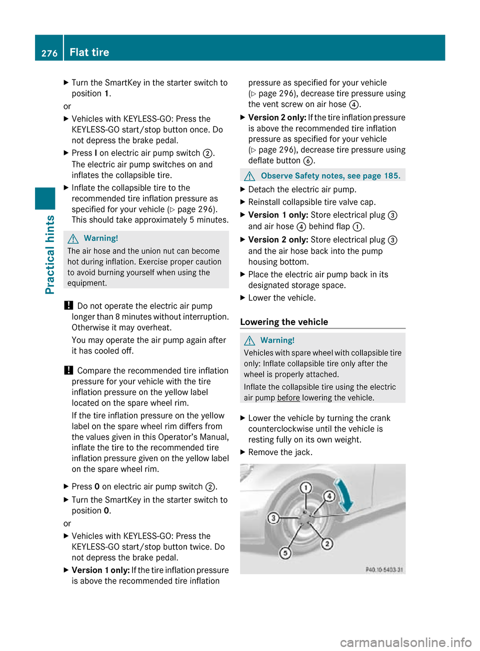
X Lower the vehicle by turning the crank
counterclockwise until the vehicle is
resting fully on its own weight.
X Remove the jack. 276
Flat tirePractical hints
219_AKB; 4; 54, en-US
d2ureepe,
Version: 2.11.8.1 2009-05-11T16:21:02+02:00 - Seite 276
Page 292 of 308

Vehicle specification CLS 550
(219.372)
The quoted data apply only to the standard
vehicle. Contact an authorized Mercedes-
Benz
Center for the corresponding data of all
special bodies and special equipment. Engine CLS 550
Engine, type
273
Mode of operation
4-stroke engine,
gasoline injection No. of cylinders
8
Bore
3.86 in (98.00 mm)
Stroke
3.56 in (90.50 mm)
Total piston
displacement
333.2 cu in
(5 461 cm 3
) Compression
ratio
10.7:1
Output acc. to
SAE J 1349
16 382 hp/6
000 rpm
(285 kW/6 000 rpm) Maximum torque
acc.
to SAE J 1349 391 lb-ft/
2 800 - 4 800 rpm
(530 Nm/
2 800 - 4 800 rpm) Maximum engine
speed
6 500 rpm
Firing order
1-5-4-2-6-3-7-8
Poly-V-belt
2 398 mm
Electrical system CLS 550
Alternator
14 V/180 A
Starter motor
12 V/1.7 kW
Battery
12 V/100 Ah Electrical system CLS 550
Spark plugs, type
Bosch F8 DPP 332U
NGK PFR 5R-11
Spark plugs,
electrode gap
0.039 in (1.0 mm)
Spark plugs,
tightening torque
18 - 22 lb-ft
(25 - 30 Nm) Main dimensions CLS 550
Overall vehicle
length
193.7 in (4
920 mm) Overall vehicle
width
17 83.0 in (2
107 mm) Overall vehicle
height
55.7 in (1
414 mm) Wheelbase
112.4 in (2
854 mm) Track, front
62.5 in (1
587 mm) Track, rear
61.8 in (1
570 mm) Turning circle
36.8 ft (11.2 m)
Weights CLS 550
Roof load
max. 220 lb (100 kg)
Trunk load
max. 220 lb (100 kg)
Vehicle specification CLS 63 AMG
(219.377)
The quoted data apply only to the standard
vehicle. Contact an authorized Mercedes-
Benz
Center for the corresponding data of all
special bodies and special equipment.
16 Premium fuel required. Performance may vary with fuel octane rating.
17 Exterior rear view mirrors folded out. 290
Vehicle specification CLS 63 AMG (219.377)
Technical data
219_AKB; 4; 54, en-US
d2ureepe,
Version: 2.11.8.1 2009-05-11T16:21:02+02:00 - Seite 290