2010 MERCEDES-BENZ CLS63AMG height
[x] Cancel search: heightPage 204 of 308

Tire size designation, load and speed
rating
:
Tire width
; Aspect ratio in %
= Radial tire code
? Rim diameter
A Load index
B Speed symbol
i For illustration purposes only. Actual data
on tires are specific to each vehicle and
may vary from data shown in above
illustration.
General: Depending on the design standards
used, the tire size molded into the sidewall
may have no letter or a letter preceding the
tire size designation.
No letter preceding the size designation (as
illustrated above): Passenger car tire based
on European design standards.
Letter “P” preceding the size designation:
Passenger car tire based on U.S. design
standards.
Letter “LT” preceding the size designation:
Light Truck tire based on U.S. design
standards.
Letter “T” preceding the size designation:
Temporary spare tires which are high
pressure compact spares designed for
temporary emergency use only.
Tire width
Tire width : indicates the nominal tire width
in millimeters. Aspect ratio
Aspect ratio
; is the dimensional
relationship between tire section height and
section width and is expressed in percentage.
The aspect ratio is arrived at by dividing
section height by section width.
Tire code
Tire code = indicates the tire construction
type. The “R” stands for radial tire type. Letter
“D” means diagonal or bias ply construction;
letter “B” means belted-bias ply construction.
At the tire manufacturer’s option, any tire
with a speed capability above 149 mph
(240 km/h) can include a “ZR” in the size
designation (for example: 245/40 ZR 18). For
additional information, see “Tire speed
rating” (Y page 203).
Rim diameter
Rim diameter ? is the diameter of the bead
seat, not the diameter of the rim edge. The
rim diameter is indicated in inches (in).
Load index G
Warning!
The tire load rating must always be at least
half of the GAWR of your vehicle. Otherwise,
tire failure may be the result which may cause
an accident and/or serious injury to you or
others.
Always replace rims and tires with the same
designation, manufacturer and type as shown
on the original part. G
Warning!
Do not overload the tires by exceeding the
specified load limit as indicated on the Tire
and Loading Information placard on the
driver’s door B-pillar. Overloading the tires
can overheat them, possibly causing a
blowout. Overloading the tires can also result
in handling or steering problems, or brake
failure.
Load index A is a numerical code associated
with the maximum load a tire can support. 202
Tires and wheelsOperation
219_AKB; 4; 54, en-US
d2ureepe,
Version: 2.11.8.1 2009-05-11T16:21:02+02:00 - Seite 202
Page 208 of 308

radio, and heater, to the extent that these
items are available as factory-installed
equipment (whether installed or not).
Air pressure
The amount of air inside the tire pressing
outward on each square inch of the tire. Air
pressure is expressed in pounds per square
inch (psi), kilopascal (kPa), or bar.
Aspect ratio
Dimensional relationship between tire
section height and section width expressed
in percentage.
Bar
Metric unit for air pressure. There are
14.5038 pounds per square inch (psi) to
1
bar; there are 100 kilopascals (kPa) to 1 bar.
Bead The tire bead contains steel wires wrapped by
steel cords that hold the tire onto the rim.
Cold tire inflation pressure
Tire inflation pressure when your vehicle has
been sitting for at least 3 hours or driven no
more than 1 mile (1.6 km).
Curb weight
The weight of a motor vehicle with standard
equipment including the maximum capacity
of fuel, oil, and coolant, and, if so equipped,
air conditioning and additional optional
equipment, but without passengers and
cargo.
DOT (Department of Transportation)
A tire branding symbol which denotes the tire
meets requirements of the U.S. Department
of Transportation. GAWR (Gross Axle Weight Rating) The GAWR is the maximum permissible axle
weight.
The gross vehicle weight on each axle
must never exceed the GAWR for the front
and rear axle indicated on the certification
label located on the driver’s door B-pillar.
GVW (Gross Vehicle Weight) The GVW comprises the weight of the vehicle
including fuel, tools, spare wheel, installed
accessories, passengers and cargo and, if
applicable,
trailer tongue load. The GVW must
never exceed the GVWR indicated on the
certification label located on the driver’s door
B-pillar.
GVWR (Gross Vehicle Weight Rating) This is the maximum permissible vehicle
weight of the fully loaded vehicle (weight of
the
vehicle including all options, passengers,
fuel, and cargo and, if applicable, trailer
tongue load). It is indicated on the
certification label located on the driver’s door
B-pillar.
Kilopascal (kPa) Metric unit for air pressure. There are 6.9 kPa
to 1 psi; another metric unit for air pressure
is bar. There are 100 kilopascals (kPa) to
1 bar.
Load index
Numerical code associated with the
maximum load a tire can support.
Maximum load rating
The maximum load in kilograms and pounds
that can be carried by the tire.
Maximum loaded vehicle weight
The sum of curb weight, accessory weight,
total load limit, and production options
weight.206
Tires and wheels
Operation
219_AKB; 4; 54, en-US
d2ureepe,
Version: 2.11.8.1 2009-05-11T16:21:02+02:00 - Seite 206
Page 234 of 308

Display messages
Possible causes/consequences and
X SolutionsFront
Passenger
Airbag
Disabled
See
Operator’s
Manual USA only:
The
front passenger front air bag is deactivated while driving
even though an adult or someone larger than a small
individual is occupying the front passenger seat. Forces
acting on the seat may make the system sense a decrease in
weight.
X Stop the vehicle in a safe location as soon as possible.
X Engage the parking brake.
X Switch off the ignition.
X Have the front passenger vacate the seat and exit the
vehicle.
X Adjust the seat height to a higher position (Y page 78).
X Make sure no objects which apply forces to the seat are
present
(e.g. objects such as books, briefcases etc. lodged
underneath, behind or around the seat). Such forces may
cause the system to sense that an occupant of a lesser
weight than actually present is on the front passenger seat.
X Keep the seat unoccupied, close the front passenger door
and switch on the ignition.
Monitor the 04 indicator lamp in the center
console (Y page 44) and the multifunction display in the
instrument cluster
(Y page 28) for the following:
With the seat unoccupied and the ignition switched on,
R the 04 indicator lamp in the center console
should illuminate and remain illuminated, indicating that
the OCS (Y page 41) has deactivated the front passenger
front air bag.
R the message Front Passenger Airbag Enabled See
Operator’s Manual or the message Front Passenger
Airbag Disabled See Operator’s Manual should not
appear in the multifunction display at any time the seat is
unoccupied. Wait at least 60 seconds for the system to
complete the necessary check cycles and to make sure
neither message appears in the multifunction display.
If above conditions are met, you can occupy the front
passenger seat again. Depending on the front passenger
classification sensed by the OCS, the 04
indicator lamp will remain illuminated or go out.
If above conditions are not met, the system is not working
properly. Have the system checked at an authorized
Mercedes-Benz Center as soon as possible. 232
Vehicle status messages in the multifunction display
Practical hints
219_AKB; 4; 54, en-US
d2ureepe,
Version: 2.11.8.1 2009-05-11T16:21:02+02:00 - Seite 232
Page 264 of 308

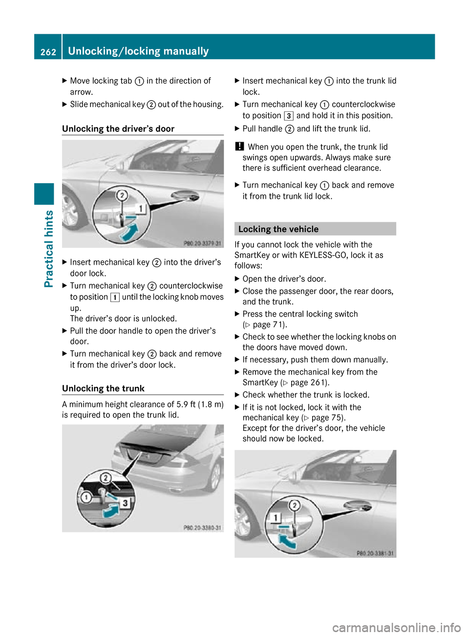
X
Move locking tab : in the direction of
arrow.
X Slide mechanical key ; out of the housing.
Unlocking the driver’s door X
Insert mechanical key ; into the driver’s
door lock.
X Turn mechanical key ; counterclockwise
to position 1 until the locking knob moves
up.
The driver’s door is unlocked.
X Pull the door handle to open the driver’s
door.
X Turn mechanical key ; back and remove
it from the driver’s door lock.
Unlocking the trunk A minimum height clearance of 5.9 ft (1.8 m)
is required to open the trunk lid. X
Insert mechanical key : into the trunk lid
lock.
X Turn mechanical key : counterclockwise
to position 3 and hold it in this position.
X Pull handle ; and lift the trunk lid.
! When you open the trunk, the trunk lid
swings open upwards. Always make sure
there is sufficient overhead clearance.
X Turn mechanical key : back and remove
it from the trunk lid lock. Locking the vehicle
If you cannot lock the vehicle with the
SmartKey or with KEYLESS-GO, lock it as
follows:
X Open the driver’s door.
X Close the passenger door, the rear doors,
and the trunk.
X Press the central locking switch
(Y page 71).
X Check to see whether the locking knobs on
the doors have moved down.
X If necessary, push them down manually.
X Remove the mechanical key from the
SmartKey (Y page 261).
X Check whether the trunk is locked.
X If it is not locked, lock it with the
mechanical key ( Y page 75).
Except for the driver’s door, the vehicle
should now be locked. 262
Unlocking/locking manuallyPractical hints
219_AKB; 4; 54, en-US
d2ureepe,
Version: 2.11.8.1 2009-05-11T16:21:02+02:00 - Seite 262
Page 275 of 308

with the jack. Do not disengage the parking
brake while the vehicle is raised.
Make sure that the ground on which the
vehicle is standing and where you place the
jack is solid, level and not slippery. If
necessary, use a large underlay. On slippery
surfaces, such as tiled floors, you should use
a non-slip underlay, for example a rubber mat.
Do not use wooden blocks or similar objects
to support the jack. Otherwise the jack may
not be able to achieve its load-bearing
capacity if it is not at its full height.
Never start the engine when the vehicle is
raised.
Also observe the notes on the jack.
X Prevent the vehicle from rolling away by
blocking wheels with wheel chocks or other
sizeable objects.
When your vehicle is equipped with a wheel
chock, it is included with the vehicle tool kit
(Y page 224). For information on setting up
the collapsible wheel chock, see
(Y page 225).
When changing a wheel on a level surface:
X Place a wheel chock or other sizeable
object in front of and another wheel chock
or other sizeable object behind the wheel
that is diagonally opposite to the wheel
being changed.
Always try lifting the vehicle using the jack on
a level surface. However, should
circumstances require you to do so on a hill:
X Place wheel chocks or other sizeable
objects on the downhill side in front of both
wheels on the side opposite to the side on
which the wheel is to be changed. G
Warning!
Only jack up the vehicle on level ground or on
slight inclines/declines. Otherwise, the
vehicle could fall off the jack and injure you or
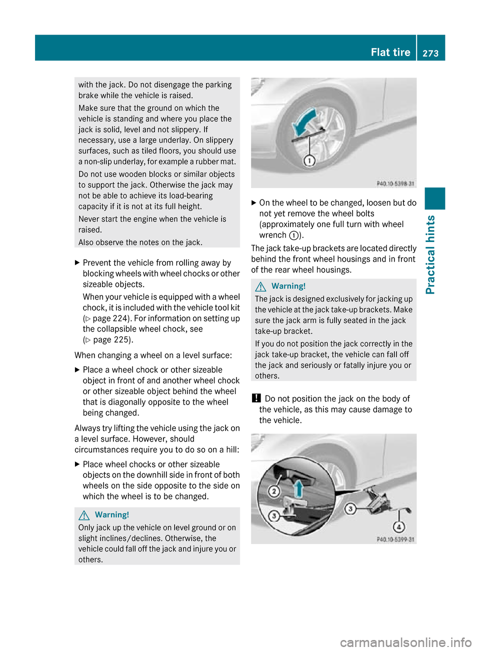
others. X
On the wheel to be changed, loosen but do
not yet remove the wheel bolts
(approximately one full turn with wheel
wrench :).
The jack take-up brackets are located directly
behind the front wheel housings and in front
of the rear wheel housings. G
Warning!
The jack is designed exclusively for jacking up
the vehicle at the jack take-up brackets. Make
sure the jack arm is fully seated in the jack
take-up bracket.
If you do not position the jack correctly in the
jack take-up bracket, the vehicle can fall off
the jack and seriously or fatally injure you or
others.
! Do not position the jack on the body of
the vehicle, as this may cause damage to
the vehicle. Flat tire
273Practical hints
219_AKB; 4; 54, en-US
d2ureepe, Version: 2.11.8.1 2009-05-11T16:21:02+02:00 - Seite 273 Z
Page 292 of 308

Vehicle specification CLS 550
(219.372)
The quoted data apply only to the standard
vehicle. Contact an authorized Mercedes-
Benz
Center for the corresponding data of all
special bodies and special equipment. Engine CLS 550
Engine, type
273
Mode of operation
4-stroke engine,
gasoline injection No. of cylinders
8
Bore
3.86 in (98.00 mm)
Stroke
3.56 in (90.50 mm)
Total piston
displacement
333.2 cu in
(5 461 cm 3
) Compression
ratio
10.7:1
Output acc. to
SAE J 1349
16 382 hp/6
000 rpm
(285 kW/6 000 rpm) Maximum torque
acc.
to SAE J 1349 391 lb-ft/
2 800 - 4 800 rpm
(530 Nm/
2 800 - 4 800 rpm) Maximum engine
speed
6 500 rpm
Firing order
1-5-4-2-6-3-7-8
Poly-V-belt
2 398 mm
Electrical system CLS 550
Alternator
14 V/180 A
Starter motor
12 V/1.7 kW
Battery
12 V/100 Ah Electrical system CLS 550
Spark plugs, type
Bosch F8 DPP 332U
NGK PFR 5R-11
Spark plugs,
electrode gap
0.039 in (1.0 mm)
Spark plugs,
tightening torque
18 - 22 lb-ft
(25 - 30 Nm) Main dimensions CLS 550
Overall vehicle
length
193.7 in (4
920 mm) Overall vehicle
width
17 83.0 in (2
107 mm) Overall vehicle
height
55.7 in (1
414 mm) Wheelbase
112.4 in (2
854 mm) Track, front
62.5 in (1
587 mm) Track, rear
61.8 in (1
570 mm) Turning circle
36.8 ft (11.2 m)
Weights CLS 550
Roof load
max. 220 lb (100 kg)
Trunk load
max. 220 lb (100 kg)
Vehicle specification CLS 63 AMG
(219.377)
The quoted data apply only to the standard
vehicle. Contact an authorized Mercedes-
Benz
Center for the corresponding data of all
special bodies and special equipment.
16 Premium fuel required. Performance may vary with fuel octane rating.
17 Exterior rear view mirrors folded out. 290
Vehicle specification CLS 63 AMG (219.377)
Technical data
219_AKB; 4; 54, en-US
d2ureepe,
Version: 2.11.8.1 2009-05-11T16:21:02+02:00 - Seite 290
Page 293 of 308

Engine CLS 63 AMG
Engine, type
156
Mode of operation
4-stroke engine,
gasoline injection No. of cylinders
8
Bore
4.02 in (102.20 mm)
Stroke
3.72 in (94.60 mm)
Total piston
displacement
378.8 cu in
(6 208 cm 3
) Compression
ratio
11.3:1
Output acc. to
SAE J 1349
18 507 hp/6
800 rpm
(378 kW/6 800 rpm) Maximum torque
acc.
to SAE J 1349 465 lb-ft/5
200 rpm
(630 Nm/5 200 rpm) Maximum engine
speed
7 200 rpm
Firing order
1-5-4-2-6-3-7-8
Poly-V-belt
2 360 mm
Electrical system CLS 63 AMG
Alternator
14 V/180 A
Starter motor
12 V/2.1 kW
Battery
12 V/95 Ah
Spark plugs, type
NGK ILZKAR 7A10
Spark plugs,
electrode gap
0.039 in (1.0 mm)
Spark plugs,
tightening torque
15 - 18 lb-ft
(20 - 25 Nm) Main dimensions CLS 63 AMG
Overall vehicle
length
193.5 in (4
915 mm) Overall vehicle
width
19 83.0 in (2
107 mm) Overall vehicle
height
54.7 in (1
389 mm) Wheelbase
112.4 in (2
854 mm) Track, front
63.0 in (1
599 mm) Track, rear
62.3 in (1
583 mm) Turning circle
37.7 ft (11.5 m)
Weights CLS 63 AMG
Roof load
max. 220 lb (100 kg)
Trunk load
max. 220 lb (100 kg)
Rims and tires
Notes
! Only
use tires which have been tested and
approved by Mercedes-Benz. Tires
approved by Mercedes-Benz are developed
to provide best possible performance in
conjunction with the driving safety systems
on your vehicle such as the ABS or the
ESP ®
. Tires specially developed for your
vehicle and tested and approved by
Mercedes-Benz can be identified by finding
the following on the tire’s sidewall:
R MO = Mercedes-Benz Original
equipment tires
R MOE
= Mercedes-Benz Original Extended
(tires with limited run-flat
characteristics) original equipment tires
Using tires other than those approved by
Mercedes-Benz may result in damage that
18 Premium fuel required. Performance may vary with fuel octane rating.
19 Exterior rear view mirrors folded out. Rims and tires
291
Technical data
219_AKB; 4; 54, en-US
d2ureepe, Version: 2.11.8.1 2009-05-11T16:21:02+02:00 - Seite 291 Z