2010 MERCEDES-BENZ C300 4MATIC battery
[x] Cancel search: batteryPage 198 of 364
iThe air recirculation mode is activated
automatically at high outside
temperatures.
The indicator lamp in button g is not lit
when the air recirculation mode is switched
on automatically.
A quantity of outside air is added after
approximately 30 minutes.XDeactivating: Press button g again.
The indicator lamp in the button goes out.
i The manually selected air recirculation
mode is deactivated automatically:
R after 5 minutes if the outside
temperature is below approximately
41‡ (5†)
R after 5 minutes if the air conditioning is
turned off
R after 30 minutes if the outside
temperature is above approximately
41‡ (5†)
Using driver-side settings for
passenger side
This feature is only available in Canada
vehicles.
You can use the settings of the driver’s side,
such as temperature, air volume and air
distribution, for the passenger side.
XActivating: Adjust the air temperature, air
volume and air distribution.XPress button ¸.
The indicator lamp in the button comes on.
The driver-side settings are used for the
passenger side.XDeactivating: Press button ¸ again.
The indicator lamp in the button goes out.Rear window defrosterGWarning!
Any accumulation of snow and ice should be
removed from the rear window before driving.
Visibility could otherwise be impaired,
endangering you and others.
The rear window defroster uses a large
amount of power. To keep the battery drain
to a minimum, switch off the defroster as
soon as the rear window is clear. The
defroster is switched off automatically after
some time of operation depending on the
outside temperature.
XSwitch on the ignition.XSwitching on: Press button ¤ on the
respective climate control panel.
The indicator lamp in the button comes on.XSwitching off: Press button ¤ again.
The rear window defroster switches off when
the battery voltage is too low. Too many
electrical consumers may be operating
simultaneously.
XSwitch off consumers that are currently not
needed if required.
Power tilt/sliding sunroof
Opening and closing
GObserve Safety notes, see page 54.GWarning!
When opening or closing the tilt/sliding
sunroof, make sure there is no danger of
anyone being harmed by the opening/closing
procedure.
The tilt/sliding sunroof is equipped with the
express operation and automatic reversal
function. If the movement of the tilt/sliding
sunroof is blocked during the closing
procedure, the tilt/sliding sunroof will stop
and open slightly.
196Power tilt/sliding sunroofControls in detail
204_AKB; 5; 23, en-USd2ureepe,Version: 2.11.8.12009-07-16T17:54:06+02:00 - Seite 196
Page 211 of 364
XSwitch on the ignition.XExtending/Retracting: Press rear
window sunshade switch : briefly.
Ashtrays
Center console ashtray
iA storage compartment is located under
the ashtray insert.
! The storage compartment is not heat-
proof. When smoking always make sure the
ashtray insert is present and properly
inserted.
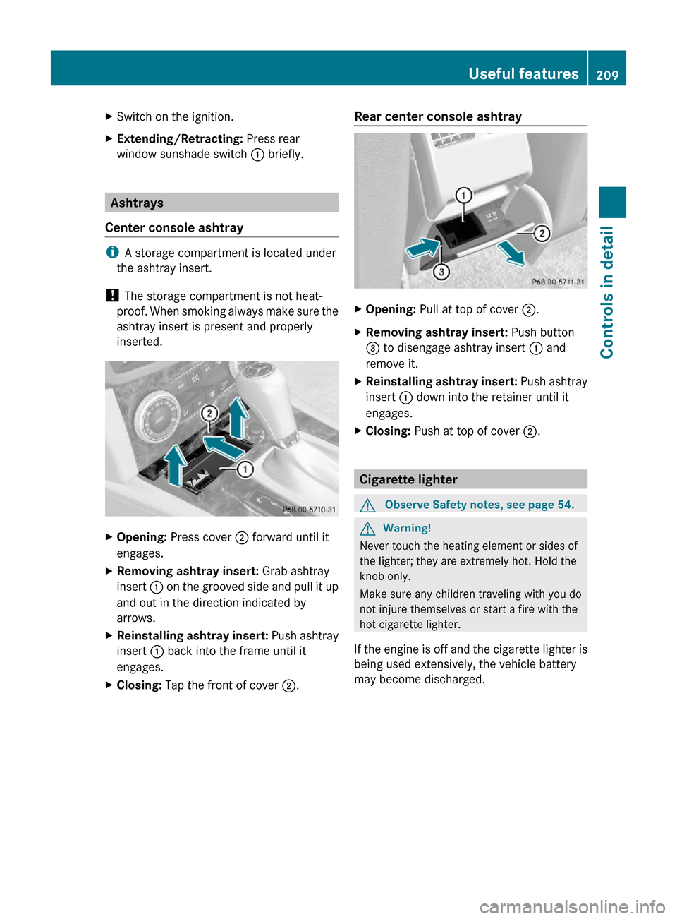
XOpening: Press cover ; forward until it
engages.
XRemoving ashtray insert: Grab ashtray
insert : on the grooved side and pull it up
and out in the direction indicated by
arrows.
XReinstalling ashtray insert: Push ashtray
insert : back into the frame until it
engages.
XClosing: Tap the front of cover ;.Rear center console ashtray XOpening: Pull at top of cover ;.XRemoving ashtray insert: Push button
= to disengage ashtray insert : and
remove it.
XReinstalling ashtray insert: Push ashtray
insert : down into the retainer until it
engages.
XClosing: Push at top of cover ;.
Cigarette lighter
GObserve Safety notes, see page 54.GWarning!
Never touch the heating element or sides of
the lighter; they are extremely hot. Hold the
knob only.
Make sure any children traveling with you do
not injure themselves or start a fire with the
hot cigarette lighter.
If the engine is off and the cigarette lighter is
being used extensively, the vehicle battery
may become discharged.
Useful features209Controls in detail204_AKB; 5; 23, en-USd2ureepe,Version: 2.11.8.12009-07-16T17:54:06+02:00 - Seite 209Z
Page 212 of 364
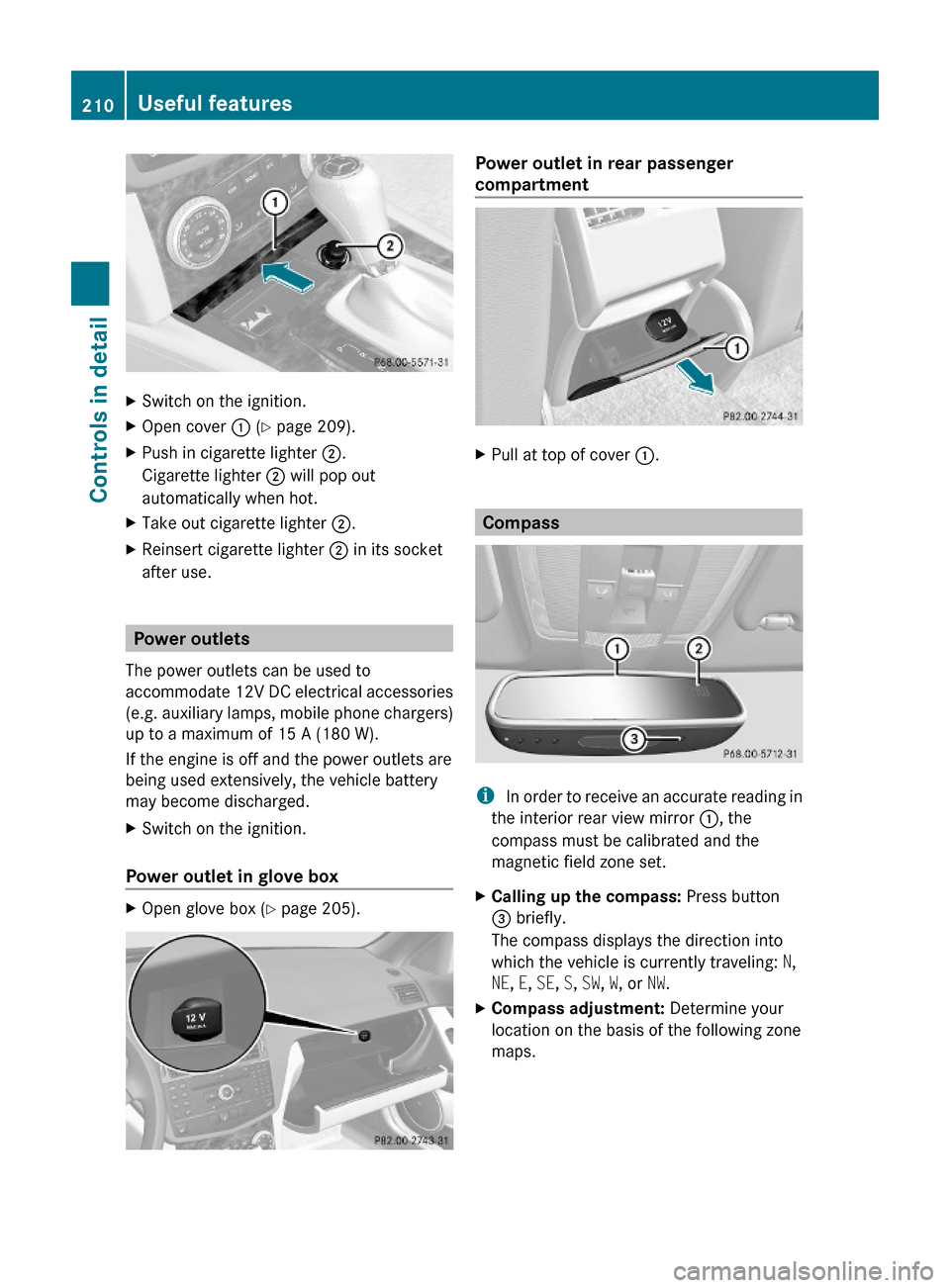
XSwitch on the ignition.XOpen cover : (Y page 209).XPush in cigarette lighter ;.
Cigarette lighter ; will pop out
automatically when hot.
XTake out cigarette lighter ;.XReinsert cigarette lighter ; in its socket
after use.
Power outlets
The power outlets can be used to
accommodate 12V DC electrical accessories
(e.g. auxiliary lamps, mobile phone chargers)
up to a maximum of 15 A (180 W).
If the engine is off and the power outlets are
being used extensively, the vehicle battery
may become discharged.
XSwitch on the ignition.
Power outlet in glove box
XOpen glove box (Y page 205).Power outlet in rear passenger
compartment
XPull at top of cover :.
Compass
i In order to receive an accurate reading in
the interior rear view mirror :, the
compass must be calibrated and the
magnetic field zone set.
XCalling up the compass: Press button
= briefly.
The compass displays the direction into
which the vehicle is currently traveling: N,
NE, E, SE, S, SW, W, or NW.
XCompass adjustment: Determine your
location on the basis of the following zone
maps.
210Useful featuresControls in detail
204_AKB; 5; 23, en-USd2ureepe,Version: 2.11.8.12009-07-16T17:54:06+02:00 - Seite 210
Page 214 of 364

access to account information, remote door
unlock and more.
The Tele Aid system is available if
R it has been activated and is operational.
Activation requires a subscription for
monitoring services, connection and
cellular air time
R vehicle battery power is available
R the relevant cellular phone network and
GPS signals are available and pass the
information on to the Customer Assistance
Center
i Location of the vehicle on a map is only
possible if the vehicle is able to receive
signals from the GPS satellite network and
pass the information on to the Customer
Assistance Center.
The Tele Aid system
(Telematic Alarm Identification on Demand)
The Tele Aid system consists of three types
of response:
R Automatic and manual emergency
R Roadside Assistance
R Information
To adjust the speaker volume during a Tele
Aid call do the following:
XPress button W or X on the
multifunction steering wheel.
or
XUse the rotary control on the audio system
( Y page 144).
Be sure to check “Owner’s Online” at
www.mbusa.com (USA only) for more
information and a description of all available
features.
System self-test
The system performs a self-test after you
have switched on the ignition.
GWarning!
A malfunction in the system has been
detected if any or all of the following
conditions occur:
R The indicator lamp in the SOS button does
not come on during the system self-test.
R The indicator lamp in the Roadside
Assistance button F does not come on
during the system self-test.
R The indicator lamp in the Information
button ï does not come on during the
system self-test.
R The indicator lamp in the SOS button,
Roadside Assistance button F, or
Information button ï remains
illuminated constantly in red after the
system self-test.
R The message Tele Aid Inoperative or
Tele Aid Not Activated appears in the
multifunction display after the system self-
test
If a malfunction is indicated as outlined above,
the system may not operate as expected. In
case of an emergency, help will have to be
summoned by other means.
Have the system checked at the nearest
Mercedes-Benz Center or contact the
Customer Assistance Center at
1-800-FOR-MERCedes (1-800-367-6372)
(USA only) or 1-888-923-8367 (Canada only)
as soon as possible.
Emergency calls
! In order to activate the Tele Aid system, a
subscriber agreement must be completed.
To ensure your system is activated and
operational, please press Information
button ï to perform the acquaintance
call. Failure to complete either of these
steps may result in a system that is not
activated.
If you have any questions regarding
activation, please call the Customer
Assistance Center at
212Useful featuresControls in detail
204_AKB; 5; 23, en-USd2ureepe,Version: 2.11.8.12009-07-16T17:54:06+02:00 - Seite 212
Page 221 of 364
control, or simply for continued use as a
hand-held remote control to operate the
respective device in other situations.
Reprogramming a single signal
transmitter button
To program a device using a signal
transmitter button previously trained, follow
these steps:
XSwitch on the ignition.XPress and hold the desired signal
transmitter button ( ;, = or ?). Do not
release the button.
Indicator lamp : will begin to flash after
20 seconds.XWithout releasing the signal transmitter
button, proceed with programming starting
with step 3.
Operation of integrated remote control
XSwitch on the ignition.XSelect and press the appropriate
integrated signal transmitter button ( ;,
= or ?) to activate the remote controlled
device.
The integrated remote control transmitter
continues to send the signal as long as the
button is pressed – up to 20 seconds.
Erasing the integrated remote control
memory
i If you sell your vehicle, erase the codes of
all three channels.
XSwitch on the ignition.XSimultaneously press and hold outer signal
transmitter buttons ; and ?, for
approximately 20 seconds, until indicator
lamp : flashes rapidly. Do not hold for
longer than 30 seconds.
The codes of all three channels are erased.Programming tips
If you are having difficulty programming the
integrated remote control, here are some
helpful tips:
R Check the frequency of hand-held remote
control A (typically located on the reverse
side of the remote). The integrated remote
control is compatible with radio-frequency
devices operating between 280-390 MHz.
R Put a new battery in hand-held remote
control A. This will increase the likelihood
of the hand-held remote control sending a
stronger and more accurate signal to the
integrated remote control.
R While performing step 3, hold hand-held
remote control A at different lengths and
angles from the signal transmitter button
( ; , = or ?) you are programming.
Attempt varying angles at the distance of 2
to 12 inches (5 to 30 cm) away or the same
angle at varying distances.
R If another hand-held remote control is
available for the same device, try the
programming steps again using that other
hand-held remote control. Make sure new
batteries are in the hand-held remote
control before beginning the procedure.
R Straighten the antenna wire from the
garage door opener assembly. This may
help improve transmitting and/or receiving
signals.
i Certain types of garage door openers are
incompatible with the integrated remote
control. If you should experience further
difficulties with programming the
integrated remote control, contact an
authorized Mercedes-Benz Center, or call
the Mercedes-Benz Customer Assistance
Center (USA only) at
1-800-FOR-MERCedes (1-800-367-6372),
or the HomeLink ®
Hotline (USA only) at
1-800-355-3515, or the Customer Service
(Canada only) at 1-800-387-0100.
Useful features219Controls in detail204_AKB; 5; 23, en-USd2ureepe,Version: 2.11.8.12009-07-16T17:54:06+02:00 - Seite 219Z
Page 253 of 364
GAWR (Gross Axle Weight Rating)
The GAWR is the maximum permissible axle
weight. The gross vehicle weight on each axle
must never exceed the GAWR for the front
and rear axle indicated on the certification
label located on the driver’s door B-pillar.
GVW (Gross Vehicle Weight)
The GVW comprises the weight of the vehicle
including fuel, tools, spare wheel, installed
accessories, passengers and cargo and, if
applicable, trailer tongue load. The GVW must
never exceed the GVWR indicated on the
certification label located on the driver’s door
B-pillar.
GVWR (Gross Vehicle Weight Rating)
This is the maximum permissible vehicle
weight of the fully loaded vehicle (weight of
the vehicle including all options, passengers,
fuel, and cargo and, if applicable, trailer
tongue load). It is indicated on the
certification label located on the driver’s door
B-pillar.
Kilopascal (kPa)
Metric unit for air pressure. There are 6.9 kPa
to 1 psi; another metric unit for air pressure
is bar. There are 100 kilopascals (kPa) to
1 bar.
Load index
Numerical code associated with the
maximum load a tire can support.
Maximum load rating
The maximum load in kilograms and pounds
that can be carried by the tire.
Maximum loaded vehicle weight
The sum of curb weight, accessory weight,
total load limit, and production options
weight.
Maximum permissible tire inflation
pressure
This number is the greatest amount of air
pressure that should ever be put in the tire.
Normal occupant weight
The number of occupants the vehicle is
designed to seat, multiplied by 68 kilograms
(150 lb).
Occupant distribution
The distribution of occupants in a vehicle at
their designated seating positions.
Production options weight
The combined weight of those installed
regular production options weighing over
5 lbs (2.3 kilograms) in excess of those
standard items which they replace, not
previously considered in curb weight or
accessory weight, including heavy duty
brakes, ride levelers, roof rack, heavy duty
battery, and special trim.
PSI (Pounds per square inch)
A standard unit of measure for air pressure.
Recommended tire inflation pressure
The recommended tire inflation pressure for
normal driving conditions is listed on the Tire
and Loading Information placard located on
the driver’s door B-pillar. It provides best
handling, tread life and riding comfort.
Supplemental information pertaining to
special driving situations can be found on the
tire inflation pressure label on the inside of
the fuel filler flap.
Rim
A metal support for a tire or a tire and tube
assembly upon which the tire beads are
seated.
Tires and wheels251Operation204_AKB; 5; 23, en-USd2ureepe,Version: 2.11.8.12009-07-16T17:54:06+02:00 - Seite 251Z
Page 262 of 364
XSwitch on the ignition.
The standard display of the control system
appears ( Y page 121).XPress button = or ; on the
multifunction steering wheel to select the
Service menu.XPress button : or 9 to select
ASSYST PLUS .XPress button a on the multifunction
steering wheel to confirm.
The maintenance service indicator display
with the maintenance service deadline
appears in the multifunction display.
i If the battery was disconnected, the days
of disconnection will not be included in the
count shown by the maintenance service
indicator. To arrive at the true maintenance
service deadline, you will need to subtract
these days from the days shown in the
maintenance service indicator message or
maintenance service indicator display.
Resetting the maintenance service
indicator
In the event that the maintenance service on
your vehicle is not carried out at an authorized
Mercedes-Benz Center, you can have the
maintenance service indicator reset.
The automotive maintenance facility carrying
out the maintenance service will find the
information for resetting the maintenance
service indicator in the maintenance-relevant
literature for your vehicle.
Such literature is available at any authorized
Mercedes-Benz Center or directly from
Mercedes-Benz.
! If the maintenance service indicator was
reset inadvertently, have an authorized
Mercedes-Benz Center correct it.
Only reset the maintenance service
indicator if the proper maintenance service
has been performed. Not following the
proper maintenance service as described
in the Maintenance Booklet will result in
engine damage and/or other vehicle
damage not covered by the Mercedes-Benz
Limited Warranty.
Vehicle care
Cleaning and care of the vehicle
Notes
Regular and proper care will help to maintain
the value of your vehicle.
GWarning!
Many cleaning products can be hazardous.
Some are poisonous, others are flammable.
Always follow the instructions on the
particular container. Always open your
vehicle’s doors or windows when cleaning the
inside.
Never use fluids or solvents that are not
designed for cleaning your vehicle.
Always lock away cleaning products and keep
them out of reach of children.
! When cleaning the vehicle, do not use
scouring agents. Never apply strong force
and only use a soft, wet cloth or sponge.
Otherwise you may scratch or damage the
surface to be cleaned.
While in operation, even while parked, your
vehicle is subjected to varying external
influences which, if gone unchecked, can
attack the paintwork as well as the vehicle
underbody and cause lasting damage.
Such damage is caused not only by extreme
and varying climatic conditions, but also by:
R Air pollution
R Road salt
R Tar
R Gravel and stone chipping
260Vehicle careOperation
204_AKB; 5; 23, en-USd2ureepe,Version: 2.11.8.12009-07-16T17:54:06+02:00 - Seite 260
Page 269 of 364
Vehicle equipment ............................268
Where will I find ...? ..........................268
Vehicle status messages in the
multifunction display .......................270
What to do if … ..................................297
Unlocking/locking manually ...........309
Resetting activated NECK-PRO
active front head restraints .............311
Replacing SmartKey batteries .........312
Replacing bulbs .................................313
Replacing wiper blades ....................316
Flat tire ..............................................317
Battery ...............................................321
Jump starting ....................................323
Towing the vehicle ............................325
Fuses ..................................................328
267Practical hints204_AKB; 5; 23, en-USd2ureepe,Version: 2.11.8.12009-07-16T17:54:06+02:00 - Seite 267