Page 89 of 496

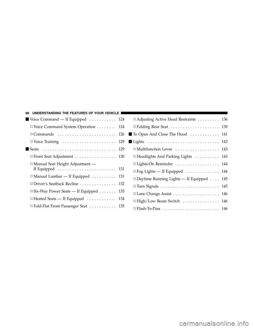
�Voice Command — If Equipped ........... 124
▫ Voice Command System Operation ........ 124
▫ Commands ........................ 126
▫ Voice Training ...................... 129
� Seats .............................. 129
▫ Front Seat Adjustment ................. 130
▫ Manual Seat Height Adjustment —
If Equipped ........................ 131
▫ Manual Lumbar — If Equipped .......... 131
▫ Driver’s Seatback Recline ............... 132
▫ Six-Way Power Seats — If Equipped ....... 133
▫ Heated Seats — If Equipped ............ 134
▫ Fold-Flat Front Passenger Seat ........... 135▫
Adjusting Active Head Restraints ......... 136
▫ Folding Rear Seat .................... 139
� To Open And Close The Hood ............ 141
� Lights ............................. 143
▫ Multifunction Lever .................. 143
▫ Headlights And Parking Lights .......... 143
▫ Lights-On Reminder .................. 144
▫ Fog Lights — If Equipped .............. 144
▫ Daytime Running Lights — If Equipped .... 145
▫ Turn Signals ........................ 145
▫ Lane Change Assist ................... 146
▫ High/Low Beam Switch ............... 146
▫ Flash-To-Pass ....................... 146
88 UNDERSTANDING THE FEATURES OF YOUR VEHICLE
Page 322 of 496

You may also experience the following when the brake
system goes into anti-lock mode:
•the ABS motor running (it may continue to run for a
short time after the stop)
•the clicking sound of solenoid valves
•brake pedal pulsations
•a slight drop or fall away of the brake pedal at the end
of the stop
These are all normal characteristics of ABS.
WARNING!
The Anti-Lock Brake System (ABS) contains sophis-
ticated electronic equipment that may be susceptible
to interference caused by improperly installed or
high output radio transmitting equipment. This in-
terference can cause possible loss of Anti-Lock brak-
ing capability. Installation of such equipment should
be performed by qualified professionals.
All vehicle wheels and tires must be the same size and
type and tires must be properly inflated to produce
accurate signals for the computer.
ELECTRONIC BRAKE CONTROL SYSTEM
Your vehicle may be equipped with an optional ad-
vanced electronic brake control system that includes
Anti-Lock Brake System (ABS), Brake Assist System
(BAS), Traction Control System (TCS), Electronic Roll
Mitigation (ERM), Hill Decent Control (HDC), Hill Start
5
STARTING AND OPERATING 321
Page 338 of 496

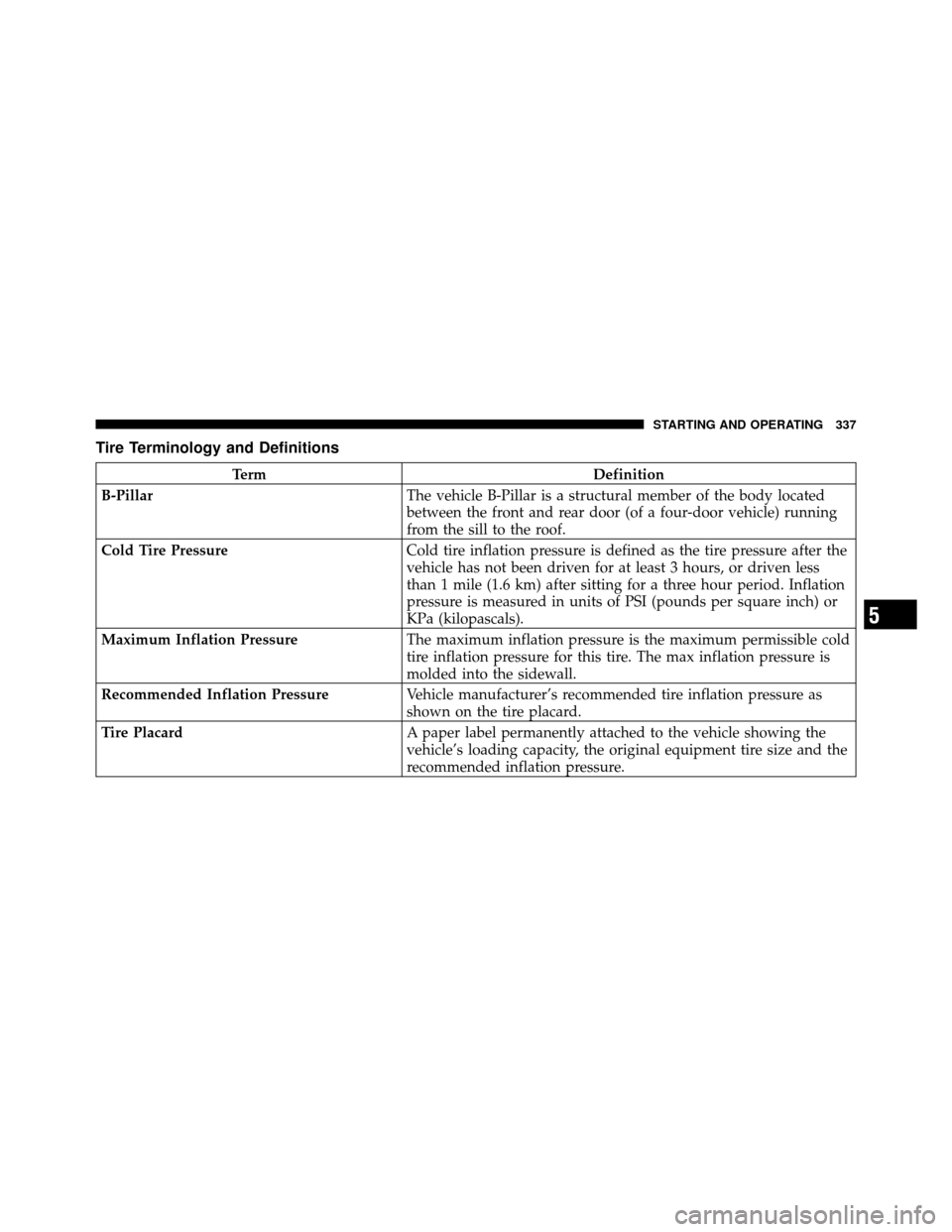
Tire Terminology and Definitions
TermDefinition
B-Pillar The vehicle B-Pillar is a structural member of the body located
between the front and rear door (of a four-door vehicle) running
from the sill to the roof.
Cold Tire Pressure Cold tire inflation pressure is defined as the tire pressure after the
vehicle has not been driven for at least 3 hours, or driven less
than 1 mile (1.6 km) after sitting for a three hour period. Inflation
pressure is measured in units of PSI (pounds per square inch) or
KPa (kilopascals).
Maximum Inflation Pressure The maximum inflation pressure is the maximum permissible cold
tire inflation pressure for this tire. The max inflation pressure is
molded into the sidewall.
Recommended Inflation Pressure Vehicle manufacturer’s recommended tire inflation pressure as
shown on the tire placard.
Tire Placard A paper label permanently attached to the vehicle showing the
vehicle’s loading capacity, the original equipment tire size and the
recommended inflation pressure.
5
STARTING AND OPERATING 337
Page 389 of 496

WARNING! (Continued)
•Always park on a firm, level surface as far from
the edge of the roadway as possible before raising
the vehicle.
•Block the wheel diagonally opposite the wheel to
be raised.
•Set the parking brake firmly and set an automatic
transmission in PARK; a manual transmission in
REVERSE.
•Never start or run the engine with the vehicle on a
jack.
•Do not let anyone sit in the vehicle when it is on a
jack.
•Do not get under the vehicle when it is on a jack.
•Only use the jack in the positions indicated and
for lifting this vehicle during a tire change.(Continued)
WARNING! (Continued)
•If working on or near a roadway, be extremely
careful of motor traffic.
•To assure that spare tires, flat or inflated, are
securely stowed, spares must be stowed with the
valve stem facing the ground.
•Turn on the Hazard Warning flasher.
1. Remove the scissors jack and lug wrench from the
spare wheel as an assembly. Turn the jack screw to the left
to loosen the lug wrench, and remove the wrench from
the jack assembly.
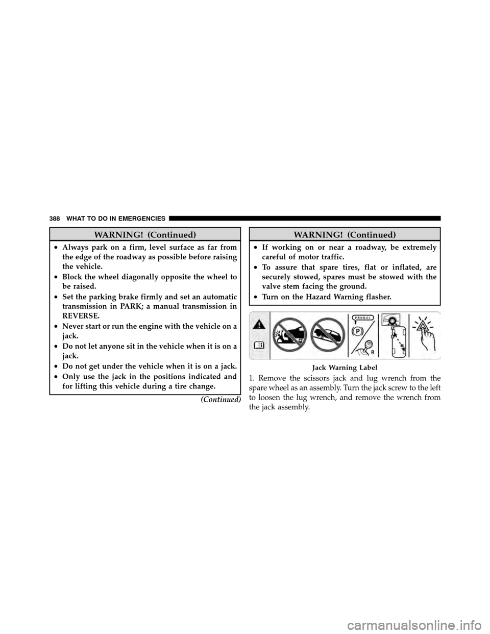
Jack Warning Label
388 WHAT TO DO IN EMERGENCIES