2010 JAGUAR XFR rjb
[x] Cancel search: rjbPage 1876 of 3039
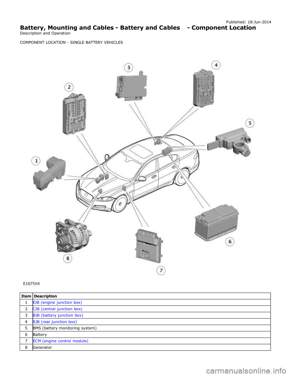
1 EJB (engine junction box) 2 CJB (central junction box) 3 BJB (battery junction box) 4 RJB (rear junction box) 5 BMS (battery monitoring system) 6 Battery 7 ECM (engine control module) 8 Generator
Page 1877 of 3039
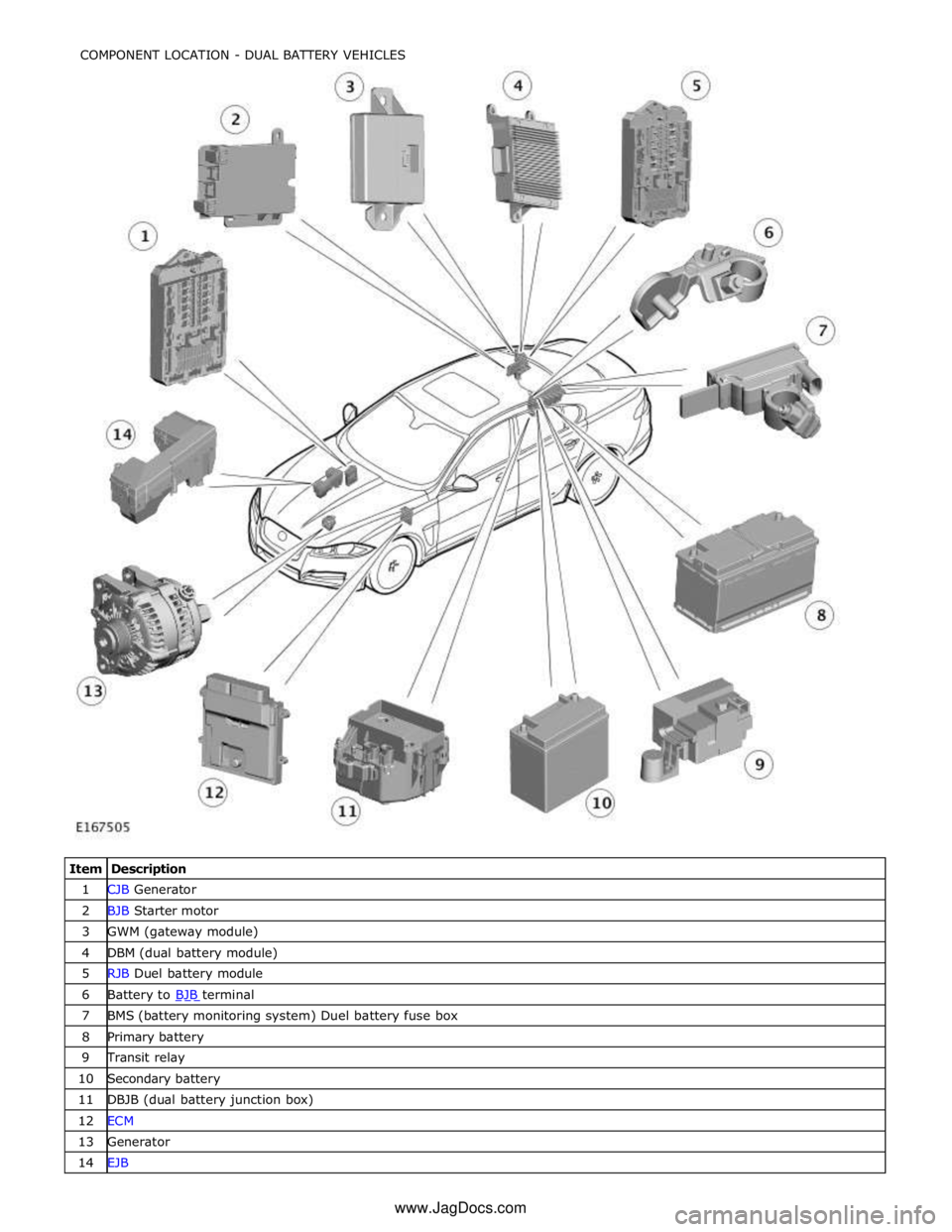
1 CJB Generator 2 BJB Starter motor 3 GWM (gateway module) 4 DBM (dual battery module) 5 RJB Duel battery module 6 Battery to BJB terminal 7 BMS (battery monitoring system) Duel battery fuse box 8 Primary battery 9 Transit relay 10 Secondary battery 11 DBJB (dual battery junction box) 12 ECM 13 Generator 14 EJB COMPONENT LOCATION - DUAL BATTERY VEHICLES
www.JagDocs.com
Page 1878 of 3039
Battery, Mounting and Cables - Battery and Cables - Overview
Description and Operation
OVERVIEW
Single Battery Vehicles Published: 18-Jun-2014
Mounted on the battery negative terminal is a BMS (battery monitoring system) module. The BMS module is integral with the
battery negative cable and is controlled by the ECM (engine control module).
CAUTION: To avoid damaging the battery monitoring system module, always use a suitable body ground point rather than
the battery negative terminal when connecting a slave power supply to the vehicle.
If a new battery is fitted to the vehicle, the BMS module will require re-calibrating using the Jaguar approved diagnostic
system.
Fitted on the battery positive terminal is a transit relay. The transit relay must be removed from the vehicle during the
Pre-Delivery Inspection (PDI). For additional information, refer to the PDI Manual.
The vehicle battery provides power to the BJB (battery junction box). The BJB contains 3 megafuses, delivering power to the RJB (rear junction box), the CJB (central junction box) and the EJB (engine junction box). In addition to containing fuses and
relays, the RJB and RJB contain software to control a number of vehicle systems. These functions are covered in the appropriate sections of this manual.
Dual Battery System Vehicles - TD42.2L Engine Variants Only
Two batteries are fitted to accommodate the dual battery system used for the Stop/Start system.
A primary battery is located in the luggage compartment floor in a plastic molded tray and secured with a metal rod. The
secondary battery is located in the DBJB (dual battery junction box).
The primary battery is a 90Ahr, 850A CCA AGM Battery.
The secondary battery is a 14Ahr, 200A CCA Absorbed Glass Mat (AGM) Battery.
A BMS (battery monitoring system) control module is mounted on the primary battery negative terminal. The BMS control
module is integral with the battery negative cable and is controlled by the GWM (gateway module).
CAUTION: To avoid damaging the BMS control module, always use the ground (negative (-)) terminal stud point on the
right side top mount. Never connect directly to the primary battery negative terminal when connecting a slave power supply to
the vehicle, the BMS control module can be damaged.
If a new primary battery is fitted to the vehicle, the BMS control module will require re-calibrating using a Jaguar approved
diagnostic system.
When the vehicle leaves the factory, a transit relay is fitted to the battery positive terminal. The transit relay is connected to
the CJB which limits the electrical functions to essential items only, to reduce loads on the primary battery. The transit relay must be removed from the vehicle during the PDI (Pre-Delivery Inspection). For additional information, refer to the PDI.
The primary battery provides power to the BJB. The BJB contains three megafuses, delivering power to the RJB, the EJB and the starter motor and generator. In addition to containing fuses and relays, the RJB and CJB contain software to control a number of vehicle systems. These functions are covered in the appropriate sections of this manual.
A jump start terminal is located adjacent to the EJB. A cover protects the terminal when not in use. If jump starting is
required, the cover must be removed and the positive (+) jump lead attached securely. The negative (-) jump lead is attached
to a stud located on the right side top mount in the engine compartment. The cover must be fitted to the positive terminal
when not in use.
Dual Battery System
The dual battery system is used on vehicles with the stop/start system. The dual battery system prevents the vehicle
electrical systems being subjected to undesirably low voltages during repeated engine restarts. If the electrical systems are
subject to low voltages the customer may notice degraded performance of components and systems and incorrect fault DTC
(diagnostic trouble code)'s may be stored.
The dual battery system isolates all electrical components and systems sensitive to low supply voltage from the primary
battery while an engine start is in progress, and supplies them from the secondary battery. Without the dual battery system,
the electrical power required by the TSS (Tandem Solenoid Starter) motor to crank the engine for each start would cause a
voltage drop across the entire vehicle electrical network, and cause control modules to function incorrectly and in some cases
reset and/or record DTC's.
If the dual battery system is unable to prevent electrical supplies to the vehicle systems being subjected to low voltage levels
during engine stop/start operations, due to the condition of the primary and/or secondary batteries or a system fault, the
stop/start feature is disabled.
Page 1879 of 3039

The dual battery system comprises the following components:
Dual Battery Module (DBM).
Dual Battery Junction Box (DBJB).
Gateway Module (GWM).
Primary battery.
Secondary battery.
The GWM hosts most of the software required to control the dual battery system and components. The GWM monitors the
components and can store fault related DTC's.
The GWM also controls the charging system software in conjunction with the ECM, RJB, CJB and ABS (anti-lock brake system) control module via the high speed and medium speed CAN (controller area network) bus. The GWM software will monitor the
status of the stop/start system and determine when a stop/start event can occur. It can also intervene to maintain vehicle
systems by keeping the engine running or initiating a restart due to, for example, climate control system requirements or
request for restart from the ECM. A brake pressure signal is received from the ABS control module which will indicate to the
GWM that an engine restart is required from driver operation of the foot brake.
The GWM contains the intelligent power management system and the BMS software. Monitoring of the primary battery
condition for stop/start is controlled by the GWM and the BMS control module.
Page 1881 of 3039
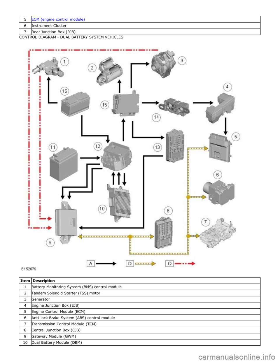
6 Instrument Cluster 7 Rear Junction Box (RJB) CONTROL DIAGRAM - DUAL BATTERY SYSTEM VEHICLES
Item Description 1 Battery Monitoring System (BMS) control module 2 Tandem Solenoid Starter (TSS) motor 3 Generator 4 Engine Junction Box (EJB) 5 Engine Control Module (ECM) 6 Anti-lock Brake System (ABS) control module 7 Transmission Control Module (TCM) 8 Central Junction Box (CJB) 9 Gateway Module (GWM) 10 Dual Battery Module (DBM)
Page 1882 of 3039

11 Secondary battery 12 Dual Battery Junction Box (DBJB) 13 Rear Junction Box (RJB) 14 Megafuse 15 Battery Junction box (BJB) 16 Primary battery
System Operation BATTERY MONITORING SYSTEM - TD4 2.2L DIESEL VEHICLES ONLY
Periodically the battery monitoring system module will instigate a self-calibration routine. To self calibrate, the battery
monitoring system first charges the battery to its full condition.
NOTE: If the vehicle is only driven for short periods the charging process could take a number of days to complete.
Once the battery is fully charged, the battery monitoring system will discharge the battery to approximately 75% of its full
state of charge, but never lower than 12.2 V. The time taken to complete this part of the routine is dependent on the electrical
load on the vehicle.
When the second part of the routine has been successfully completed, the battery monitoring system will return the battery to
its optimum level of charge. The optimum level of charge will be between 12.6 V and 15 V, depending on battery condition,
temperature and loading.
The battery monitoring system module also monitors the battery condition with the engine switched off. If a low voltage
condition is detected the module can request the infotainment system is switched off to protect battery voltage. Once the
infotainment system has been switched off, the vehicle must be run for at least 5 minutes to charge the battery before the
infotainment system can be operated with the engine switched off.
BATTERY MONITORING SYSTEM - SINGLE AND DUAL BATTERY SYSTEM VEHICLES
When the ignition is off (power mode 0), the BMS control module records the primary battery state of charge and begins to
monitor the battery condition from this point.
If the battery state of charge falls by 7%, the BMS control module will monitor the primary battery for 5 minutes. If after the 5
minute monitoring period, the primary battery charge has continued to fall due to the quiescent drain current being too high,
the BMS control module will determine that some control modules are still 'awake'. The BMS control module sends a shutdown
message on the LIN (local interconnect network) bus to the GWM (Gateway Module). The GWM sends a CAN (controller area
network) bus message on both the medium and high speed networks to all control modules, requesting them to shutdown.
The BMS control module will monitor the primary battery state of charge for a further 5 minutes and determine if the primary
battery state of charge is still dropping. If a quiescent drain current continues, the primary battery state of charge will
continue to drop. If the state of charge falls to 12% of the initial monitoring value, the BMS control module determines that
one or more control modules are still awake and a failure to respond to the shutdown request may indicate an error state
within the control module(s).
BMS Low Battery Warning and Energy Management Messages
The BMS continuously monitors the condition of the primary vehicle battery. If excessive battery discharge occurs, the system
will begin to shut down non-essential electrical systems in order to protect the battery.
If the BMS calculates that battery condition is not within set parameters, there are 3 messages that can be displayed, 2 on the
touch screen and 1 on the message center. These inform the user that the battery is either at a low level of charge or the
engine-off power consumption limit has been exceeded.
Low Battery - Please switch engine on or system will shutdown in 3 minutes: is displayed as a Warning on the
touch screen if the engine is not running. This indicates that the battery has fallen below a predefined threshold. As
soon as the battery is charged back above this threshold then the message will be removed.
Low Battery - Please start your engine is displayed on the message center if the engine is not running. This indicates
that the battery has fallen below a predefined threshold. As soon as the battery is charged back above this threshold
then the message will be removed or it can be manually removed by pressing 'OK'.
System will shut down in 3 minutes: is displayed as an Energy management on the touch screen if the engine is not
running, and system features are causing excessive battery discharge. After 3 minutes the BMS will begin shutting
down vehicle systems. Normal system operation will resume when the engine is started.
This is based on a percentage of battery capacity available for the customer to use with the engine off. The percentage can
change based upon several factors.
Once triggered, the resetting of this message will not occur until the vehicle is driven for 10 minutes with the engine running
(to allow the battery to recoup any lost charge). However, if the engine is run for less than 10 minutes, the message will only
be displayed after an additional 5 minutes with the ignition on but engine off.
BMS Control Module Self Calibration
Periodically the BMS control module will instigate a self-calibration routine. To self calibrate, the battery monitoring system www.JagDocs.com
Page 1887 of 3039
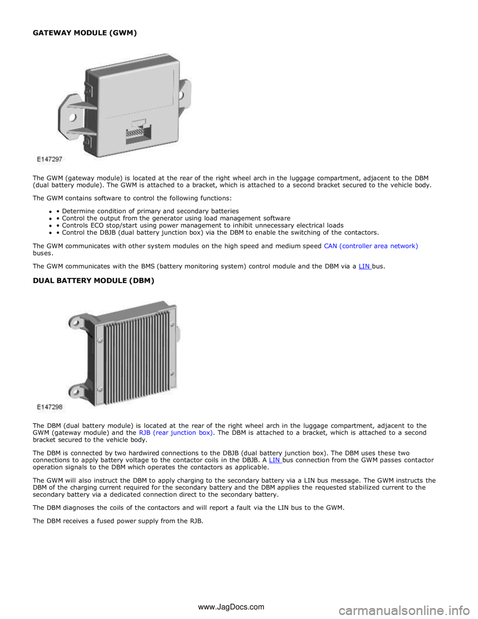
DUAL BATTERY MODULE (DBM)
The DBM (dual battery module) is located at the rear of the right wheel arch in the luggage compartment, adjacent to the
GWM (gateway module) and the RJB (rear junction box). The DBM is attached to a bracket, which is attached to a second
bracket secured to the vehicle body.
The DBM is connected by two hardwired connections to the DBJB (dual battery junction box). The DBM uses these two
connections to apply battery voltage to the contactor coils in the DBJB. A LIN bus connection from the GWM passes contactor operation signals to the DBM which operates the contactors as applicable.
The GWM will also instruct the DBM to apply charging to the secondary battery via a LIN bus message. The GWM instructs the
DBM of the charging current required for the secondary battery and the DBM applies the requested stabilized current to the
secondary battery via a dedicated connection direct to the secondary battery.
The DBM diagnoses the coils of the contactors and will report a fault via the LIN bus to the GWM.
The DBM receives a fused power supply from the RJB. www.JagDocs.com
Page 1911 of 3039
Published: 11-May-2011
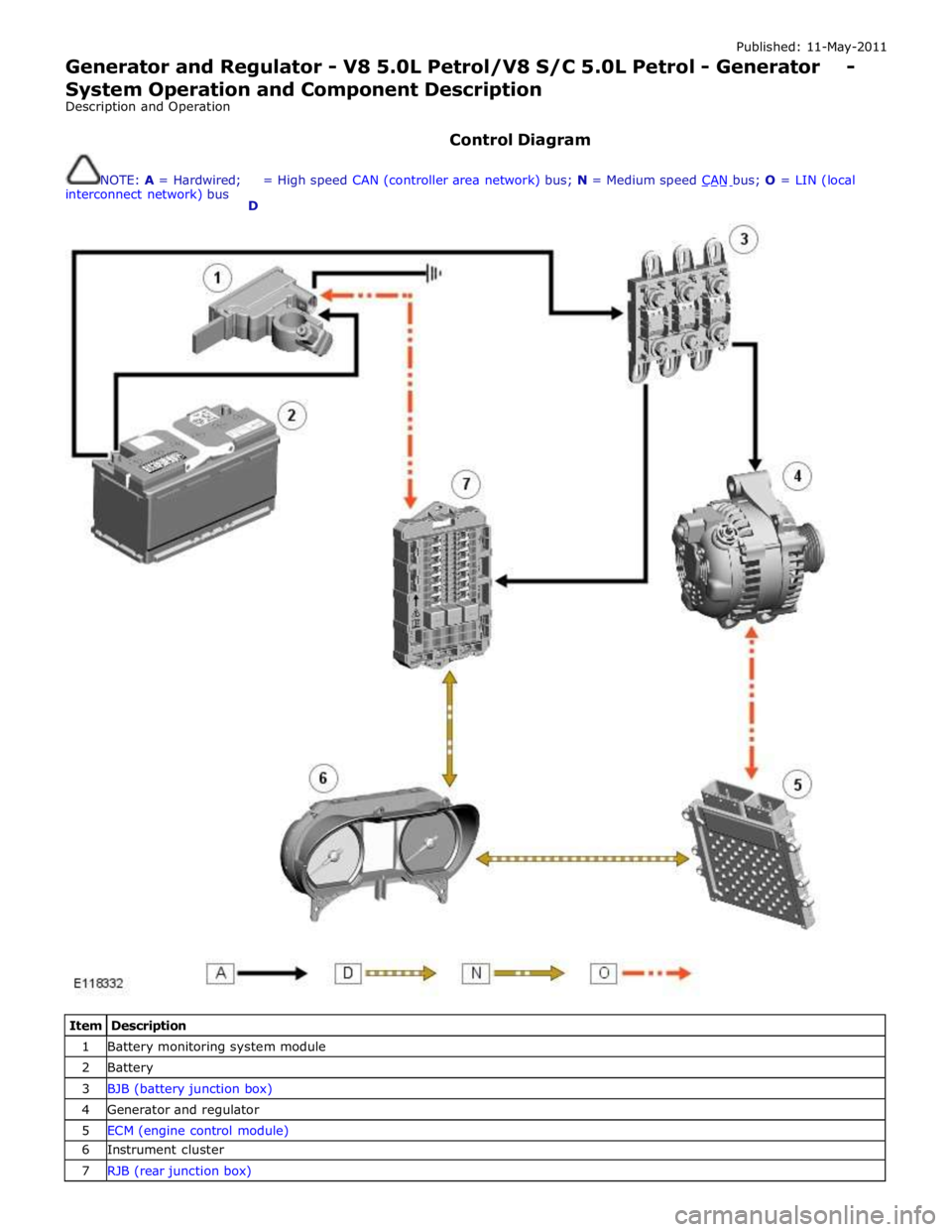
Generator and Regulator - V8 5.0L Petrol/V8 S/C 5.0L Petrol - Generator - System Operation and Component Description
Description and Operation
Control Diagram
NOTE: A = Hardwired;
interconnect network) bus
D = High speed CAN (controller area network) bus; N = Medium speed CAN bus; O = LIN (local
Item Description 1 Battery monitoring system module 2 Battery 3 BJB (battery junction box) 4 Generator and regulator 5 ECM (engine control module) 6 Instrument cluster 7 RJB (rear junction box)