Page 2212 of 3039
Motor (501-11 Glass, Frames and Mechanisms, Removal and Installation).
8. Remove the exterior mirror.
For additional information, refer to: Exterior Mirror (501-09 Rear View Mirrors, Removal and Installation).
9. Remove the front door latch.
For additional information, refer to: Front Door Latch (501-14 Handles, Locks, Latches and Entry Systems, Removal and Installation).
10. Remove the front door outer window frame mouldings.
11. Remove the front door weatherstrips.
12. Remove the front door wiring harness.
13. Remove the front door impact absorbers.
14. Remove the front door check strap.
15. Remove the front door glass run felt.
Page 2253 of 3039

Interior Trim and Ornamentation - Headliner
Removal and Installation
Removal
NOTE: Removal steps in this procedure may contain installation details. Published: 11-May-2011
1. Refer to: Battery Disconnect and Connect (414-01 Battery, Mounting and Cables, General Procedures).
2. Refer to: Interior Rear View Mirror (501-09 Rear View Mirrors, Removal and Installation).
3. Refer to: Overhead Console (501-12 Instrument Panel and Console, Removal and Installation).
4.
Remove both sun visors.
Refer to: Sun Visor (501-05 Interior Trim and Ornamentation, Removal and Installation).
5.
Remove both A-pillar trim panels.
Refer to: A-Pillar Trim Panel (501-05 Interior Trim and Ornamentation, Removal and Installation).
6.
Remove both B-pillar upper trim panels.
Refer to: B-Pillar Upper Trim Panel (501-05 Interior Trim and Ornamentation, Removal and Installation).
7.
Remove both C-pillar trim panels.
Refer to: C-Pillar Trim Panel (501-05 Interior Trim and Ornamentation, Removal and Installation).
8.
Remove both front seats.
Refer to: Front Seat (501-10 Seating, Removal and Installation).
9. Refer to: Rear Seat Cushion (501-10 Seating, Removal and Installation).
Page 2281 of 3039
Interior Trim and Ornamentation - Sun Visor Vanity Mirror
Removal and Installation
General Equipment Published: 28-Jan-2013
Removal
Installation
1. Using a suitable tool, release the retaining clips and
remove the sun visor vanity mirror from the sun visor.
General Equipment: Interior trim remover
1. CAUTION: Do not use excessive force to install the
component.
Press firmly against the areas indicated until an audible
click is heard. Interior trim remover
Page 2290 of 3039
Exterior mirror retaining nuts 8 — 71 Exterior mirror motor retaining screws 1 — 9
Page 2291 of 3039
Rear View Mirrors - Rear View Mirrors - Component Location
Description and Operation
NOTE: LHD (left-hand drive) shown RHD (right-hand drive) similar Published: 11-May-2011
Item Description 1 Passenger door mirror 2 Passenger door control module 3 Interior mirror 4 Drivers door control module 5 Mirror control switch 6 Drivers door mirror
Page 2292 of 3039

Rear View Mirrors - Rear View Mirrors - Overview
Description and Operation
Overview
The exterior mirrors incorporate the following:
Blind spot monitoring indicator
Auto dimming function
Turn signal indicators
Approach lamps
Exterior temperature sensor
Heated mirror function
Reverse dipping function Published: 11-May-2011
Movement of the door mirrors is controlled from a switch pack located on the drivers door. The switch pack contains 2
non-latching mirror select buttons labeled 'L' and 'R' and a 4-way mirror movement switch. Door mirror movement commands
are transmitted to the driver's door module over the LIN (local interconnect network) bus. The drivers door module transmits
any mirror movement commands to the passenger door module over the medium speed CAN (controller area network) bus.
Movement of the door mirrors is carried out by the respective door module. The door modules provide supply and ground paths
to the mirror motors and monitor mirror position via potentiometers located in the mirror housings.
Both exterior door mirrors and the interior mirror feature an auto dimming function. The interior rear view mirror contains one
forward and one reward facing light sensor. The light sensors control the auto dimming feature of the interior mirror to reduce
glare from the headlights of following vehicles.
When auto-dimming of the interior mirror is required, a supply is provided by the interior mirror to both door mirrors to initiate
the door mirror auto-dimming sequence.
Blind spot monitoring function alerts the driver to a vehicle located in the vehicle blind spot. A warning indicator is located in
each exterior mirror towards the outer edge.
Refer to: Blindspot Monitoring System (413-09 Warning Devices, Description and Operation).
Page 2293 of 3039
Published: 04-Nov-2013
Rear View Mirrors - Rear View Mirrors - System Operation and Component Description
Description and Operation
Control Diagram
NOTE: A = Hardwired, N = Medium speed CAN (controller area network) bus, O = LIN (local interconnect network) bus
Item Description 1 RJB (rear junction box) 2 RH (right-hand) door module 3 RH door mirror 4 LH (left-hand)side door mirror 5 Interior mirror 6 Battery
Page 2294 of 3039

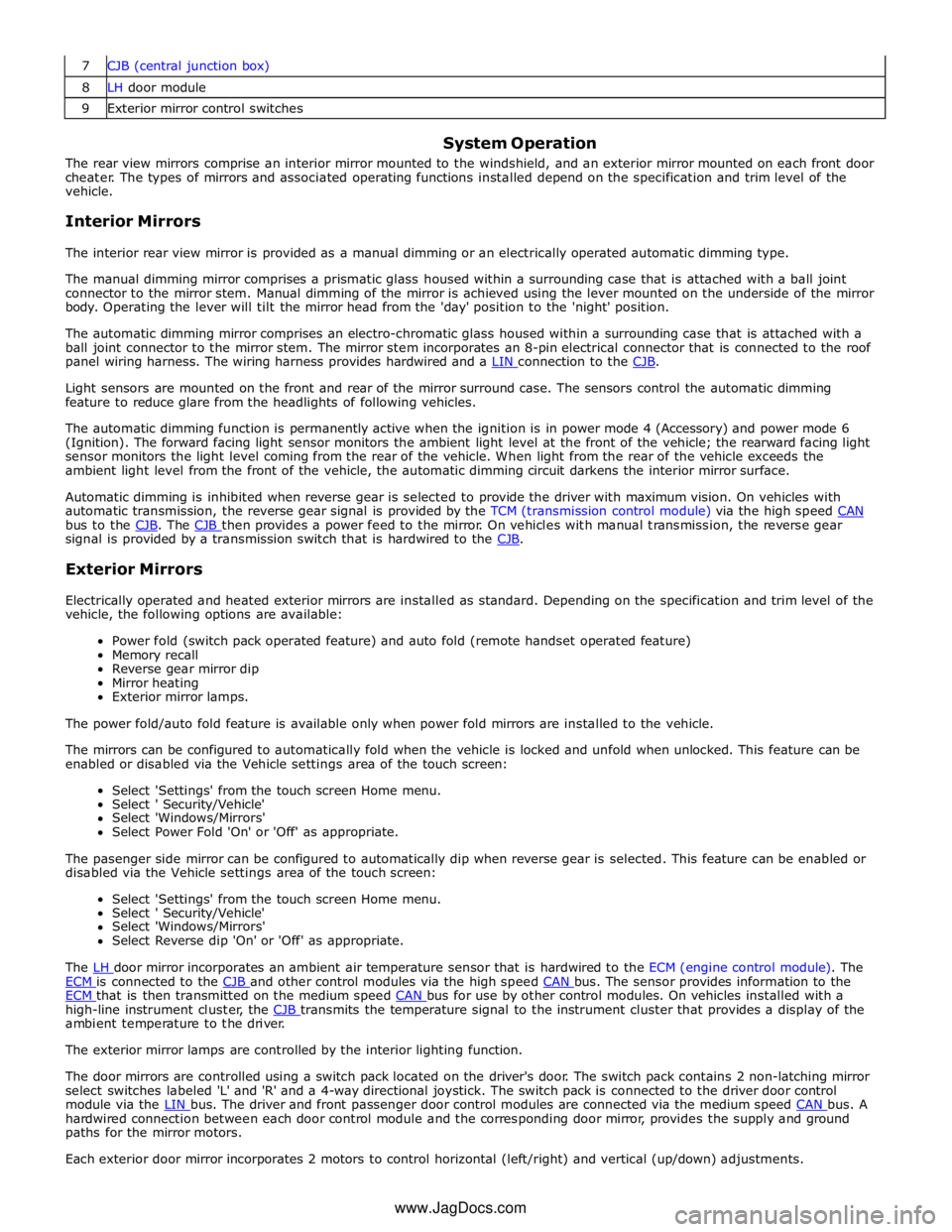
8 LH door module 9 Exterior mirror control switches
System Operation
The rear view mirrors comprise an interior mirror mounted to the windshield, and an exterior mirror mounted on each front door
cheater. The types of mirrors and associated operating functions installed depend on the specification and trim level of the
vehicle.
Interior Mirrors
The interior rear view mirror is provided as a manual dimming or an electrically operated automatic dimming type.
The manual dimming mirror comprises a prismatic glass housed within a surrounding case that is attached with a ball joint
connector to the mirror stem. Manual dimming of the mirror is achieved using the lever mounted on the underside of the mirror
body. Operating the lever will tilt the mirror head from the 'day' position to the 'night' position.
The automatic dimming mirror comprises an electro-chromatic glass housed within a surrounding case that is attached with a
ball joint connector to the mirror stem. The mirror stem incorporates an 8-pin electrical connector that is connected to the roof
panel wiring harness. The wiring harness provides hardwired and a LIN connection to the CJB.
Light sensors are mounted on the front and rear of the mirror surround case. The sensors control the automatic dimming
feature to reduce glare from the headlights of following vehicles.
The automatic dimming function is permanently active when the ignition is in power mode 4 (Accessory) and power mode 6
(Ignition). The forward facing light sensor monitors the ambient light level at the front of the vehicle; the rearward facing light
sensor monitors the light level coming from the rear of the vehicle. When light from the rear of the vehicle exceeds the
ambient light level from the front of the vehicle, the automatic dimming circuit darkens the interior mirror surface.
Automatic dimming is inhibited when reverse gear is selected to provide the driver with maximum vision. On vehicles with
automatic transmission, the reverse gear signal is provided by the TCM (transmission control module) via the high speed CAN bus to the CJB. The CJB then provides a power feed to the mirror. On vehicles with manual transmission, the reverse gear signal is provided by a transmission switch that is hardwired to the CJB.
Exterior Mirrors
Electrically operated and heated exterior mirrors are installed as standard. Depending on the specification and trim level of the
vehicle, the following options are available:
Power fold (switch pack operated feature) and auto fold (remote handset operated feature)
Memory recall
Reverse gear mirror dip
Mirror heating
Exterior mirror lamps.
The power fold/auto fold feature is available only when power fold mirrors are installed to the vehicle.
The mirrors can be configured to automatically fold when the vehicle is locked and unfold when unlocked. This feature can be
enabled or disabled via the Vehicle settings area of the touch screen:
Select 'Settings' from the touch screen Home menu.
Select ' Security/Vehicle'
Select 'Windows/Mirrors'
Select Power Fold 'On' or 'Off' as appropriate.
The pasenger side mirror can be configured to automatically dip when reverse gear is selected. This feature can be enabled or
disabled via the Vehicle settings area of the touch screen:
Select 'Settings' from the touch screen Home menu.
Select ' Security/Vehicle'
Select 'Windows/Mirrors'
Select Reverse dip 'On' or 'Off' as appropriate.
The LH door mirror incorporates an ambient air temperature sensor that is hardwired to the ECM (engine control module). The ECM is connected to the CJB and other control modules via the high speed CAN bus. The sensor provides information to the ECM that is then transmitted on the medium speed CAN bus for use by other control modules. On vehicles installed with a high-line instrument cluster, the CJB transmits the temperature signal to the instrument cluster that provides a display of the ambient temperature to the driver.
The exterior mirror lamps are controlled by the interior lighting function.
The door mirrors are controlled using a switch pack located on the driver's door. The switch pack contains 2 non-latching mirror
select switches labeled 'L' and 'R' and a 4-way directional joystick. The switch pack is connected to the driver door control
module via the LIN bus. The driver and front passenger door control modules are connected via the medium speed CAN bus. A hardwired connection between each door control module and the corresponding door mirror, provides the supply and ground
paths for the mirror motors.
Each exterior door mirror incorporates 2 motors to control horizontal (left/right) and vertical (up/down) adjustments. www.JagDocs.com