2010 JAGUAR XFR Electrical
[x] Cancel search: ElectricalPage 2941 of 3039
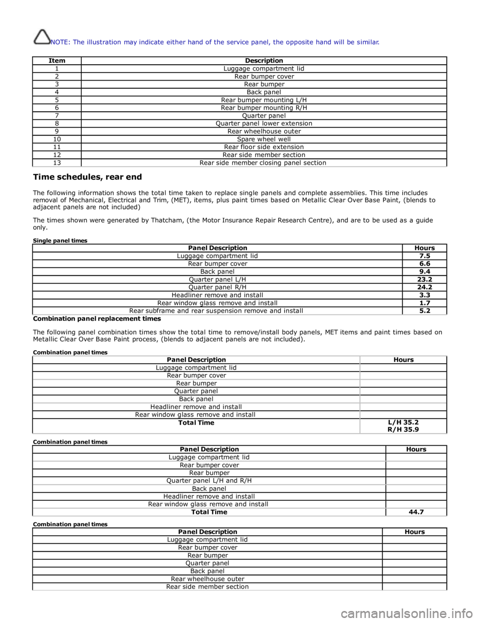
NOTE: The illustration may indicate either hand of the service panel, the opposite hand will be similar.
Item Description 1 Luggage compartment lid 2 Rear bumper cover 3 Rear bumper 4 Back panel 5 Rear bumper mounting L/H 6 Rear bumper mounting R/H 7 Quarter panel 8 Quarter panel lower extension 9 Rear wheelhouse outer 10 Spare wheel well 11 Rear floor side extension 12 Rear side member section 13 Rear side member closing panel section Time schedules, rear end
The following information shows the total time taken to replace single panels and complete assemblies. This time includes
removal of Mechanical, Electrical and Trim, (MET), items, plus paint times based on Metallic Clear Over Base Paint, (blends to
adjacent panels are not included)
The times shown were generated by Thatcham, (the Motor Insurance Repair Research Centre), and are to be used as a guide
only.
Single panel times
Panel Description Hours Luggage compartment lid 7.5 Rear bumper cover 6.6 Back panel 9.4 Quarter panel L/H 23.2 Quarter panel R/H 24.2 Headliner remove and install 3.3 Rear window glass remove and install 1.7 Rear subframe and rear suspension remove and install 5.2 Combination panel replacement times
The following panel combination times show the total time to remove/install body panels, MET items and paint times based on
Metallic Clear Over Base Paint process, (blends to adjacent panels are not included).
Combination panel times
Panel Description Hours Luggage compartment lid Rear bumper cover Rear bumper Quarter panel Back panel Headliner remove and install Rear window glass remove and install Total Time L/H 35.2
R/H 35.9 Combination panel times
Panel Description Hours Luggage compartment lid Rear bumper cover Rear bumper Quarter panel L/H and R/H Back panel Headliner remove and install Rear window glass remove and install Total Time 44.7 Combination panel times
Panel Description Hours Luggage compartment lid Rear bumper cover Rear bumper Quarter panel Back panel Rear wheelhouse outer Rear side member section
Page 2943 of 3039
Rear End Sheet Metal Repairs - Back Panel
Removal and Installation
Removal Published: 11-May-2011
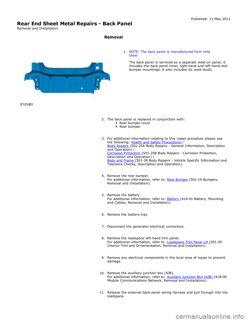
1. NOTE: The back panel is manufactured from mild
steel.
The back panel is serviced as a separate weld-on panel, it
includes the back panel inner, right-hand and left-hand rear
bumper mountings, it also includes its weld studs.
2. The back panel is replaced in conjunction with:
Rear bumper cover
Rear bumper
3. For additional information relating to this repair procedure please see
the following: Health and Safety Precautions / Body Repairs (501-25A Body Repairs - General Information, Description and Operation) /
Corrosion Protection (501-25B Body Repairs - Corrosion Protection, Description and Operation) /
Body and Frame (501-26 Body Repairs - Vehicle Specific Information and Tolerance Checks, Description and Operation).
4. Remove the rear bumper.
For additional information, refer to: Rear Bumper (501-19 Bumpers, Removal and Installation).
5. Remove the battery.
For additional information, refer to: Battery (414-01 Battery, Mounting and Cables, Removal and Installation).
6. Remove the battery tray.
7. Disconnect the generator electrical connectors.
8. Remove the loadspace left-hand trim panel.
For additional information, refer to: Loadspace Trim Panel LH (501-05 Interior Trim and Ornamentation, Removal and Installation).
9. Remove any electrical components in the local area of repair to prevent
damage.
10. Remove the auxiliary junction box (AJB).
For additional information, refer to: Auxiliary Junction Box (AJB) (418-00 Module Communications Network, Removal and Installation).
11. Release the external back panel wiring harness and pull through into the
loadspace.
Page 2949 of 3039
Removal and Installation).
7. Remove the battery.
For additional information, refer to: Battery (414-01 Battery, Mounting and Cables, Removal and Installation).
8. Disconnect the generator electrical connectors.
9. If the left-hand rear quarter panel is to be repaired, remove the
loadspace left-hand trim panel.
For additional information, refer to: Loadspace Trim Panel LH (501-05 Interior Trim and Ornamentation, Removal and Installation).
10. If the right-hand rear quarter panel is to be repaired, remove the
auxiliary junction box (AJB).
For additional information, refer to: Auxiliary Junction Box (AJB) (418-00 Module Communications Network, Removal and Installation).
11. Remove any electrical components in the local area of repair to prevent
damage.
12. Remove the rear muffler.
For additional information, refer to: Rear Muffler (309-00C Exhaust System - V8 5.0L Petrol/V8 S/C 5.0L Petrol, Removal and Installation) /
Rear Muffler (309-00C Exhaust System - V8 5.0L Petrol/V8 S/C 5.0L Petrol, Removal and Installation) /
Rear Muffler (309-00C Exhaust System - V8 5.0L Petrol/V8 S/C 5.0L Petrol, Removal and Installation).
13. Remove the exhaust muffler and tailpipe heatshield.
14. Remove the rear scuff plate trim panel.
For additional information, refer to: Rear Scuff Plate Trim Panel (501-05 Interior Trim and Ornamentation, Removal and Installation).
15. Remove the loadspace trim panel.
For additional information, refer to: Loadspace Trim Panel (501-05 Interior Trim and Ornamentation, Removal and Installation).
16. Remove the forced air extraction grille.
17. Release and lay aside the back panel and loadspace wiring harness.
18. Remove the luggage compartment lid weatherstrip.
19. Remove the rear bumper cover side retainer.
20. Remove the roof moulding.
21. Remove the headliner.
For additional information, refer to: Headliner (501-05 Interior Trim and Ornamentation, Removal and Installation).
22. Remove the side air curtain module.
www.JagDocs.com
Page 2960 of 3039
(100-00 General Information, Description and Operation) /
Body Repairs (501-25A Body Repairs - General Information, Description and Operation) /
Corrosion Protection (501-25B Body Repairs - Corrosion Protection, Description and Operation) /
Body and Frame (501-26 Body Repairs - Vehicle Specific Information and Tolerance Checks, Description and Operation).
4. Remove the battery.
For additional information, refer to: Battery (414-01 Battery, Mounting and Cables, Removal and Installation).
5. Disconnect the generator electrical connectors.
6. Remove any electrical components in the local area of repair to prevent
damage.
7. Remove the Rear Bumper.
For additional information, refer to: Rear Bumper (501-19 Bumpers, Removal and Installation).
8. Remove the rear muffler.
For additional information, refer to: Rear Muffler (309-00C Exhaust System - V8 5.0L Petrol/V8 S/C 5.0L Petrol, Removal and Installation) /
Rear Muffler (309-00C Exhaust System - V8 5.0L Petrol/V8 S/C 5.0L Petrol, Removal and Installation) /
Rear Muffler (309-00C Exhaust System - V8 5.0L Petrol/V8 S/C 5.0L Petrol, Removal and Installation).
9. Remove the exhaust muffler and tailpipe heatshield.
10. Remove the forced air extraction grille.
Page 2964 of 3039
Rear End Sheet Metal Repairs - Rear Bumper Mounting
Removal and Installation
Removal Published: 11-May-2011
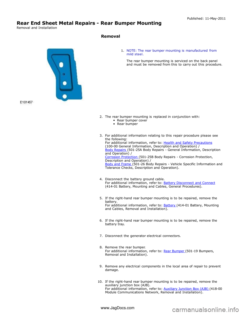
1. NOTE: The rear bumper mounting is manufactured from
mild steel.
The rear bumper mounting is serviced on the back panel
and must be removed from this to carry out this procedure.
2. The rear bumper mounting is replaced in conjunction with:
Rear bumper cover
Rear bumper
3. For additional information relating to this repair procedure please see
the following:
For additional information, refer to: Health and Safety Precautions (100-00 General Information, Description and Operation) /
Body Repairs (501-25A Body Repairs - General Information, Description and Operation) /
Corrosion Protection (501-25B Body Repairs - Corrosion Protection, Description and Operation) /
Body and Frame (501-26 Body Repairs - Vehicle Specific Information and Tolerance Checks, Description and Operation).
4. Disconnect the battery ground cable.
For additional information, refer to: Battery Disconnect and Connect (414-01 Battery, Mounting and Cables, General Procedures).
5. If the right-hand rear bumper mounting is to be repaired, remove the
battery.
For additional information, refer to: Battery (414-01 Battery, Mounting and Cables, Removal and Installation).
6. If the right-hand rear bumper mounting is to be repaired, remove the
battery tray.
7. Disconnect the generator electrical connectors.
8. Remove the rear bumper.
For additional information, refer to: Rear Bumper (501-19 Bumpers, Removal and Installation).
9. Remove any electrical components in the local area of repair to prevent
damage.
10. If the right-hand rear bumper mounting is to be repaired, remove the
auxiliary junction box (AJB).
For additional information, refer to: Auxiliary Junction Box (AJB) (418-00 Module Communications Network, Removal and Installation). www.JagDocs.com
Page 2967 of 3039
Rear End Sheet Metal Repairs - Rear Floor Side Extension
Removal and Installation
Removal Published: 11-May-2011
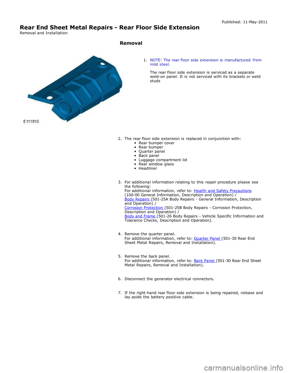
1. NOTE: The rear floor side extension is manufactured from
mild steel.
The rear floor side extension is serviced as a separate
weld-on panel. It is not serviced with its brackets or weld
studs
2. The rear floor side extension is replaced in conjunction with:
Rear bumper cover
Rear bumper
Quarter panel
Back panel
Luggage compartment lid
Rear window glass
Headliner
3. For additional information relating to this repair procedure please see
the following:
For additional information, refer to: Health and Safety Precautions (100-00 General Information, Description and Operation) /
Body Repairs (501-25A Body Repairs - General Information, Description and Operation) /
Corrosion Protection (501-25B Body Repairs - Corrosion Protection, Description and Operation) /
Body and Frame (501-26 Body Repairs - Vehicle Specific Information and Tolerance Checks, Description and Operation).
4. Remove the quarter panel.
For additional information, refer to: Quarter Panel (501-30 Rear End Sheet Metal Repairs, Removal and Installation).
5. Remove the back panel.
For additional information, refer to: Back Panel (501-30 Rear End Sheet Metal Repairs, Removal and Installation).
6. Disconnect the generator electrical connectors.
7. If the right-hand rear floor side extension is being repaired, release and
lay aside the battery positive cable.
Page 2975 of 3039
Body and Frame (501-26 Body Repairs - Vehicle Specific Information and Tolerance Checks, Description and Operation).
7. Disconnect the generator electrical connectors.
8. Remove the luggage compartment lid.
For additional information, refer to: Luggage Compartment Lid (501-03 Body Closures, Removal and Installation).
9. Remove the spare wheel well.
For additional information, refer to: Spare W heel Well (501-30 Rear End Sheet Metal Repairs, Removal and Installation).
10. Remove the rear floor side extension.
For additional information, refer to: Rear Floor Side Extension (501-30 Rear End Sheet Metal Repairs, Removal and Installation).
11. Remove the rear muffler hanger bracket from the side member.
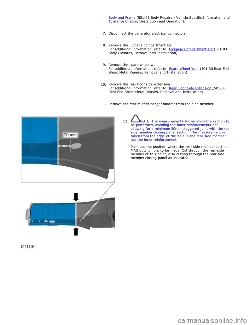
12. NOTE: The measurements shown allow the section to
be performed, avoiding the inner reinforcements and
allowing for a minimum 50mm staggered joint with the rear
side member closing panel section. The measurement is
taken from the edge of the hole in the rear side member,
not the inner reinforcement.
Mark out the position where the rear side member section
MAG butt joint is to be made. Cut through the rear side
member at this point, also cutting through the rear side
member closing panel as indicated.
Page 2981 of 3039
Section (501-29 Side Panel Sheet Metal Repairs, Removal and Installation).
6. Disconnect the generator electrical connectors.
7. Remove the rear safety belt retractor.
For additional information, refer to: Rear Safety Belt Retractor (501-20A Safety Belt System, Removal and Installation).
8. Disconnect, release the inner quarter panel wiring harness and position
it to one side.
9. If the right-hand rear wheelhouse outer is being repaired, release the
battery positive cable and position it to one side.
10. Release the inner quarter panel insulating material and position it to
one side.
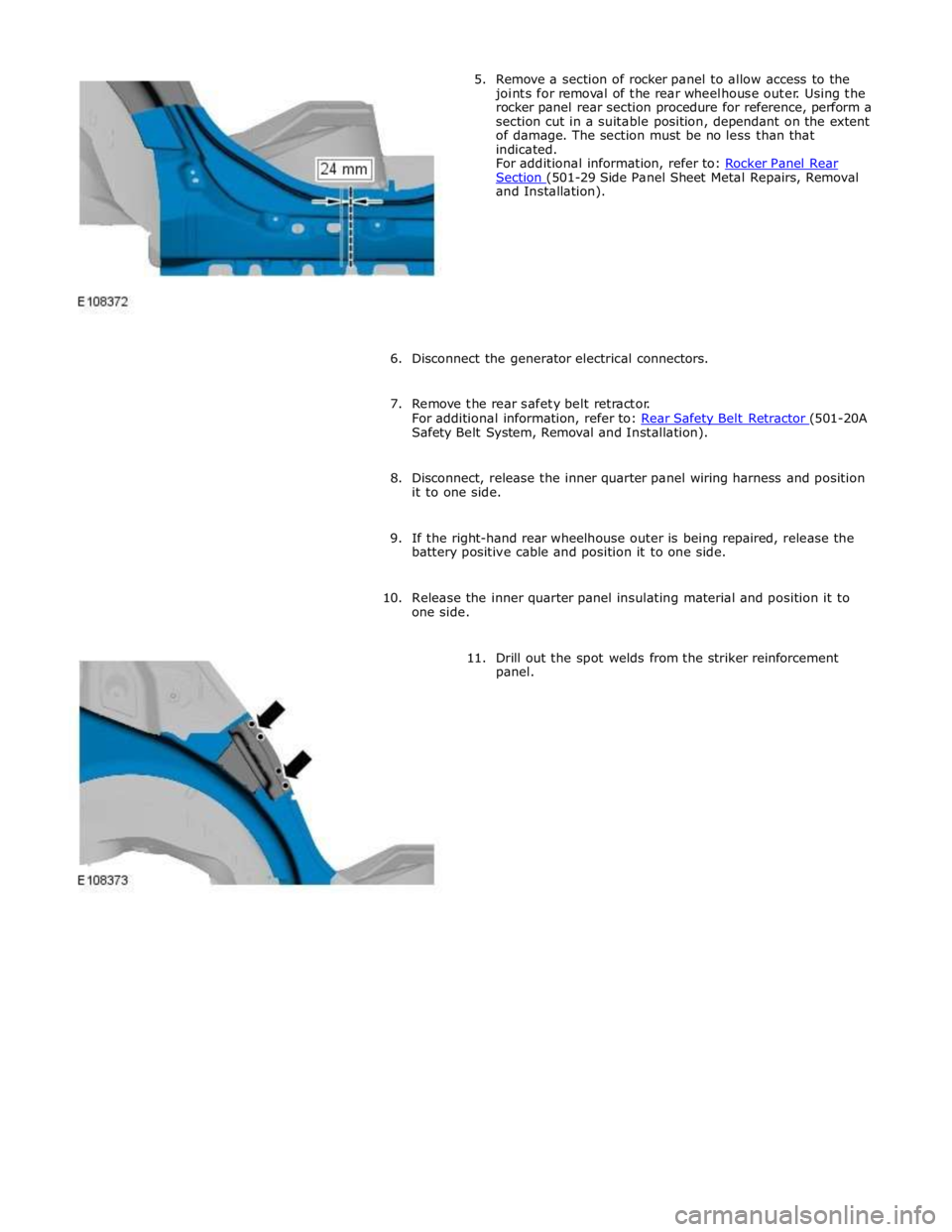
11. Drill out the spot welds from the striker reinforcement
panel.