2010 JAGUAR XFR trip computer
[x] Cancel search: trip computerPage 1829 of 3039
module and fuel injector operating data from the ECM.
A 'Trip' button is located on the end of the LH (left-hand) multifunction switch and allows the driver to access, in sequence, the
available trip information by repeatedly pressing the button. The trip information is displayed in the following order:
Trip distance – The trip distance since the last reset is displayed
Average speed – The average speed since the last reset is displayed
Average fuel consumption – The average fuel consumption since the last reset is displayed
Range – The range is displayed showing the distance which can be travelled until the fuel gage reads empty. If the
range display shows dashes (-), this indicates a failure with one or both of the fuel level sensors.
The trip computer has three independent memories; A, B and Auto. Memories A and B can be set independently. The Auto
memory is reset after each ignition cycle and therefore only contains information relating the current journey.
The trip information can also be accessed from the TSD located in the center console. The TSD allows the same information
available with the trip button on the multifunction switch to be displayed on the TSD, with the addition of the option to reset
the values in the A and B memories.
If the battery is disconnected, all trip data in memories A, B and Auto are erased.
Fuel Level Display
The fuel level display is a linear LCD display to show the usable fuel tank contents. The level display is active at all times when the ignition is on. Low fuel level is displayed as a LOW FUEL LEVEL message and an amber warning triangle in the
message center.
The fuel level is obtained by fuel level sensors in the fuel tank. These are monitored by the RJB software and their output resistance values, corresponding fuel quantity, are transmitted to the instrument cluster on the medium speed CAN bus. The instrument cluster uses the two level sensor signals to calculate the fuel tank contents. This calculation takes into account
fuel movement in the tank to display a steady fuel quantity in the LCD.
The fuel level information is transmitted on the medium speed and high speed CAN bus for use by other vehicle system modules.
AUDIBLE WARNINGS
The instrument cluster can generate audible warnings to alert the driver to a displayed message and change of vehicle
operating condition. The audible warning is generated by a sounder located within the instrument cluster. The audible warnings
can be generated for the warnings below and are listed in order of priority, with the first being the highest priority:
Seatbelt reminder
EPB (High Pitch)
ACC Driver Intervene 1
Airbag fault
Key in ignition switch
ASL overspeed
ACC Driver Intervene 2
EPB (Low Pitch)
Vehicle armed (entry delay)
JaguarDrive selector not in park
Valet mode
Lights on reminder
Hood operation
Passive Entry / Passive Start (PEPS)
Memory set
Turn signal indicators
Seat Belt Minder.
The audible warnings can take the form of a single chime, a number of chimes or a continuous chime. The audible warnings are
initiated by a CAN message request from the requesting sub-system control module or by the instrument cluster software.
Page 1949 of 3039
systems.
A typical example of information transfer is vehicle speed information from the ABS (anti-lock brake system) module used to
control the automatic volume control function. The vehicle speed information from the ABS module is sent on the high speed
CAN network and collected by the instrument panel gateway. The signal is passed to the medium speed CAN network and onto the ICM gateway. The ICM calculates the volume adjustment required. The corrected audio volume level signal is sent on the
MOST network to the IAM or Power amplifier (dependant on vehicle equipment level) for output to the speaker system.
AUDIO SYSTEM USER CONTROLS
Touch-Screen
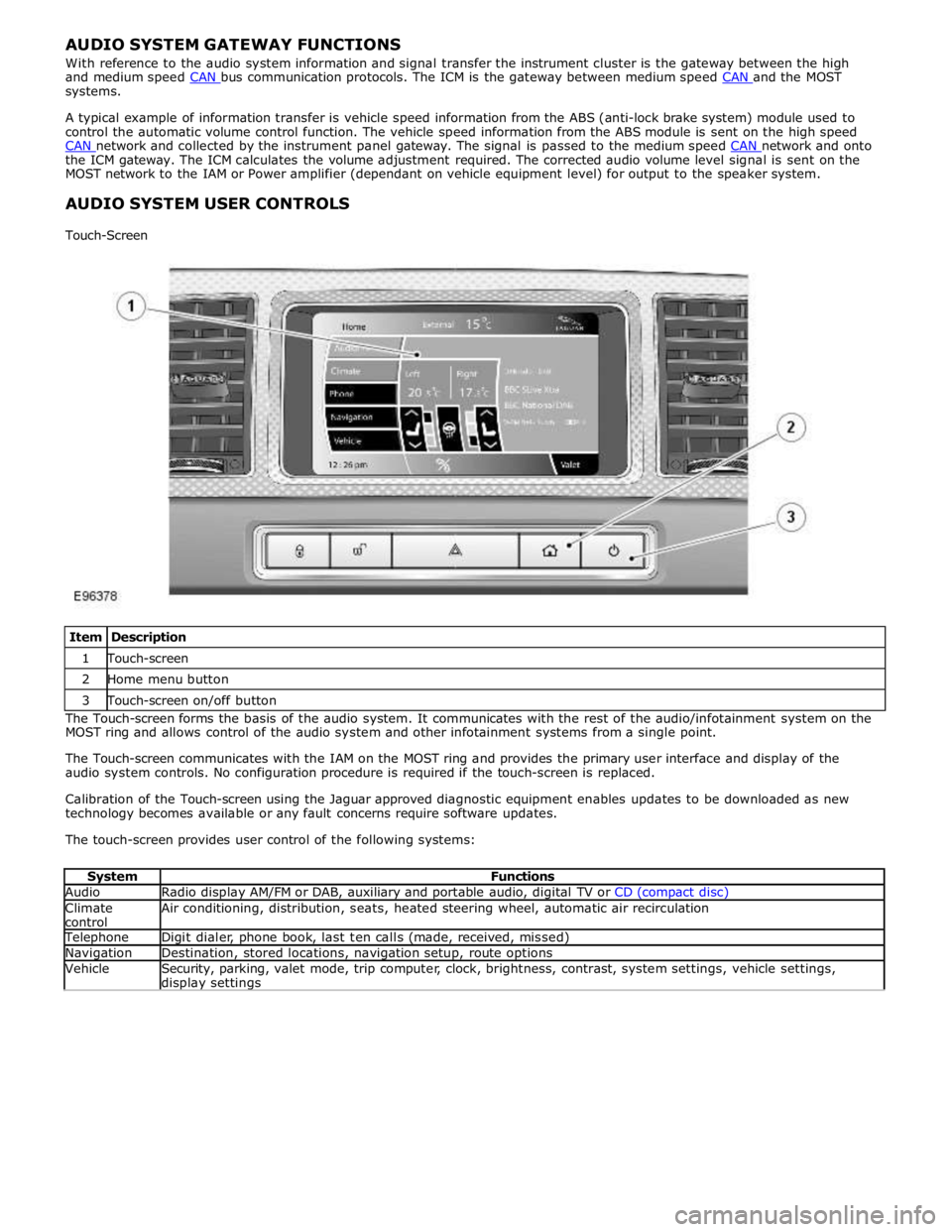
Item Description 1 Touch-screen 2 Home menu button 3 Touch-screen on/off button The Touch-screen forms the basis of the audio system. It communicates with the rest of the audio/infotainment system on the
MOST ring and allows control of the audio system and other infotainment systems from a single point.
The Touch-screen communicates with the IAM on the MOST ring and provides the primary user interface and display of the
audio system controls. No configuration procedure is required if the touch-screen is replaced.
Calibration of the Touch-screen using the Jaguar approved diagnostic equipment enables updates to be downloaded as new
technology becomes available or any fault concerns require software updates.
The touch-screen provides user control of the following systems:
System Functions Audio Radio display AM/FM or DAB, auxiliary and portable audio, digital TV or CD (compact disc) Climate
control Air conditioning, distribution, seats, heated steering wheel, automatic air recirculation Telephone Digit dialer, phone book, last ten calls (made, received, missed) Navigation Destination, stored locations, navigation setup, route options Vehicle
Security, parking, valet mode, trip computer, clock, brightness, contrast, system settings, vehicle settings, display settings
Page 1953 of 3039
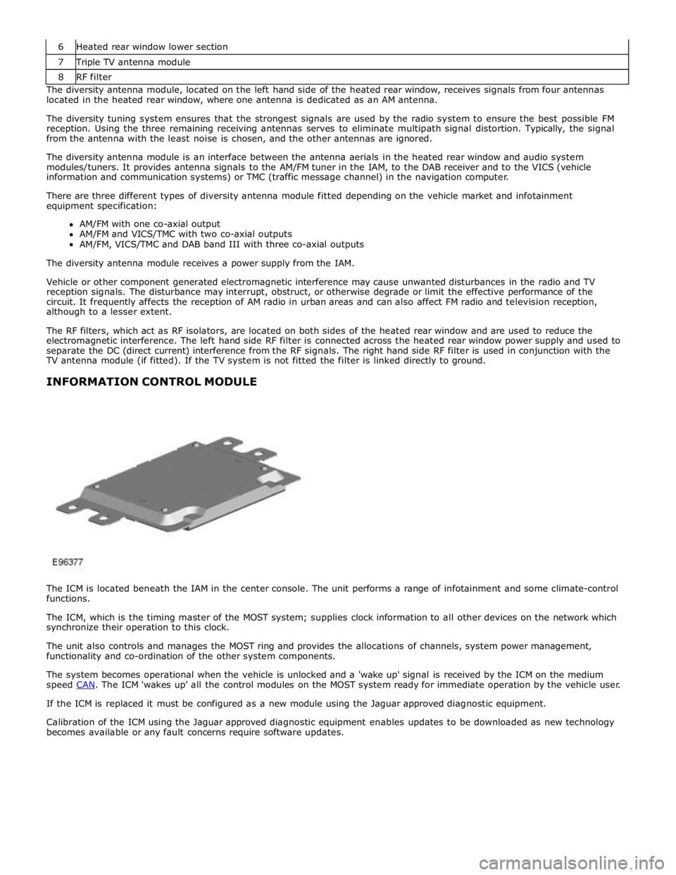
7 Triple TV antenna module 8 RF filter The diversity antenna module, located on the left hand side of the heated rear window, receives signals from four antennas
located in the heated rear window, where one antenna is dedicated as an AM antenna.
The diversity tuning system ensures that the strongest signals are used by the radio system to ensure the best possible FM
reception. Using the three remaining receiving antennas serves to eliminate multipath signal distortion. Typically, the signal
from the antenna with the least noise is chosen, and the other antennas are ignored.
The diversity antenna module is an interface between the antenna aerials in the heated rear window and audio system
modules/tuners. It provides antenna signals to the AM/FM tuner in the IAM, to the DAB receiver and to the VICS (vehicle
information and communication systems) or TMC (traffic message channel) in the navigation computer.
There are three different types of diversity antenna module fitted depending on the vehicle market and infotainment
equipment specification:
AM/FM with one co-axial output
AM/FM and VICS/TMC with two co-axial outputs
AM/FM, VICS/TMC and DAB band III with three co-axial outputs
The diversity antenna module receives a power supply from the IAM.
Vehicle or other component generated electromagnetic interference may cause unwanted disturbances in the radio and TV
reception signals. The disturbance may interrupt, obstruct, or otherwise degrade or limit the effective performance of the
circuit. It frequently affects the reception of AM radio in urban areas and can also affect FM radio and television reception,
although to a lesser extent.
The RF filters, which act as RF isolators, are located on both sides of the heated rear window and are used to reduce the
electromagnetic interference. The left hand side RF filter is connected across the heated rear window power supply and used to
separate the DC (direct current) interference from the RF signals. The right hand side RF filter is used in conjunction with the
TV antenna module (if fitted). If the TV system is not fitted the filter is linked directly to ground.
INFORMATION CONTROL MODULE
The ICM is located beneath the IAM in the center console. The unit performs a range of infotainment and some climate-control
functions.
The ICM, which is the timing master of the MOST system; supplies clock information to all other devices on the network which
synchronize their operation to this clock.
The unit also controls and manages the MOST ring and provides the allocations of channels, system power management,
functionality and co-ordination of the other system components.
The system becomes operational when the vehicle is unlocked and a 'wake up' signal is received by the ICM on the medium
speed CAN. The ICM 'wakes up' all the control modules on the MOST system ready for immediate operation by the vehicle user. If the ICM is replaced it must be configured as a new module using the Jaguar approved diagnostic equipment.
Calibration of the ICM using the Jaguar approved diagnostic equipment enables updates to be downloaded as new technology
becomes available or any fault concerns require software updates.
Page 1981 of 3039
Navigation Destination, stored locations, navigation setup, route options Vehicle
Security, parking, valet mode, trip computer, clock, brightness, contrast, system settings, vehicle settings, display settings The screen is a touch sensitive 7 inch LCD (liquid crystal display) VGA screen containing 800 x 480 pixels in a 15:9 format. The
screen processes its own video for system operation but receives the navigation graphics from the navigation computer.
Steering Wheel Controls
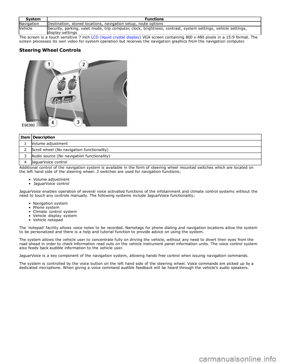
Item Description 1 Volume adjustment 2 Scroll wheel (No navigation functionality) 3 Audio source (No navigation functionality) 4 JaguarVoice control Additional control of the navigation system is available in the form of steering wheel mounted switches which are located on
the left hand side of the steering wheel. 2 switches are used for navigation functions;
Volume adjustment
JaguarVoice control
JaguarVoice enables operation of several voice activated functions of the infotainment and climate control systems without the
need to touch any controls manually. The following systems include JaguarVoice functionality;
Navigation system
Phone system
Climate control system
Vehicle display system
Vehicle notepad
The 'notepad' facility allows voice notes to be recorded. Nametags for phone dialing and navigation locations allow the system
to be personalized and there is a help and tutorial function to provide advice on using the system.
The system allows the vehicle user to concentrate fully on driving the vehicle, without any need to divert their eyes from the
road ahead in order to check information read outs on the vehicle instrument panel information units. The voice control system
also feeds back audible information to the vehicle user.
JaguarVoice is a key component of the navigation system, allowing hands free control when issuing navigation commands.
The system is controlled by the voice button on the left hand side of the steering wheel. Voice commands are picked up by a
dedicated microphone. When giving a voice command audible feedback will be heard through the vehicle’s audio speakers.
Page 2029 of 3039
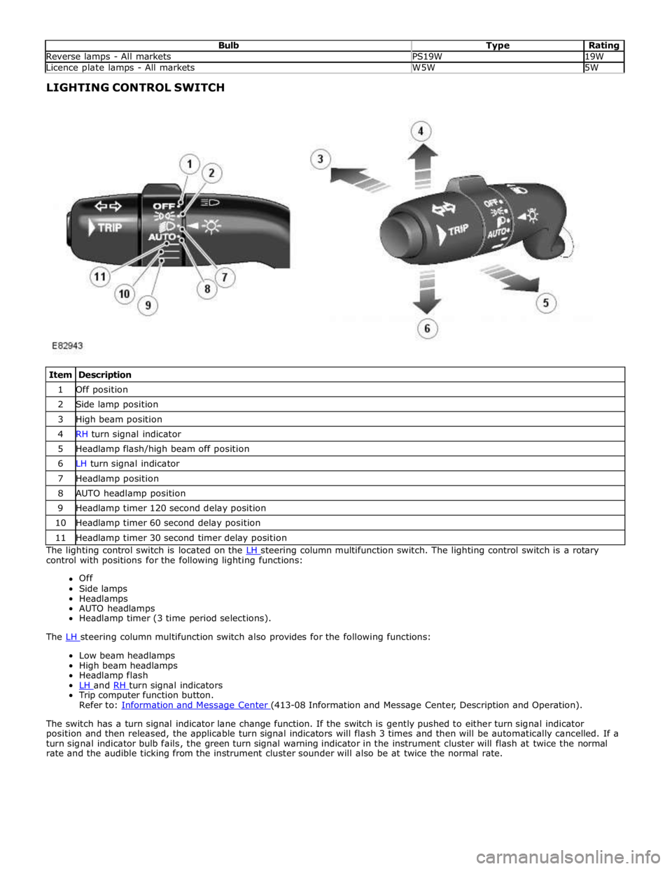
Bulb Type Rating Reverse lamps - All markets PS19W 19W Licence plate lamps - All markets W5W 5W LIGHTING CONTROL SWITCH
Item Description 1 Off position 2 Side lamp position 3 High beam position 4 RH turn signal indicator 5 Headlamp flash/high beam off position 6 LH turn signal indicator 7 Headlamp position 8 AUTO headlamp position 9 Headlamp timer 120 second delay position 10 Headlamp timer 60 second delay position 11 Headlamp timer 30 second timer delay position The lighting control switch is located on the LH steering column multifunction switch. The lighting control switch is a rotary control with positions for the following lighting functions:
Off
Side lamps
Headlamps
AUTO headlamps
Headlamp timer (3 time period selections).
The LH steering column multifunction switch also provides for the following functions: Low beam headlamps
High beam headlamps
Headlamp flash
LH and RH turn signal indicators Trip computer function button.
Refer to: Information and Message Center (413-08 Information and Message Center, Description and Operation).
The switch has a turn signal indicator lane change function. If the switch is gently pushed to either turn signal indicator
position and then released, the applicable turn signal indicators will flash 3 times and then will be automatically cancelled. If a
turn signal indicator bulb fails, the green turn signal warning indicator in the instrument cluster will flash at twice the normal
rate and the audible ticking from the instrument cluster sounder will also be at twice the normal rate.