2010 JAGUAR XFR radio antenna
[x] Cancel search: radio antennaPage 1987 of 3039
1
2
3
4
5
6
7
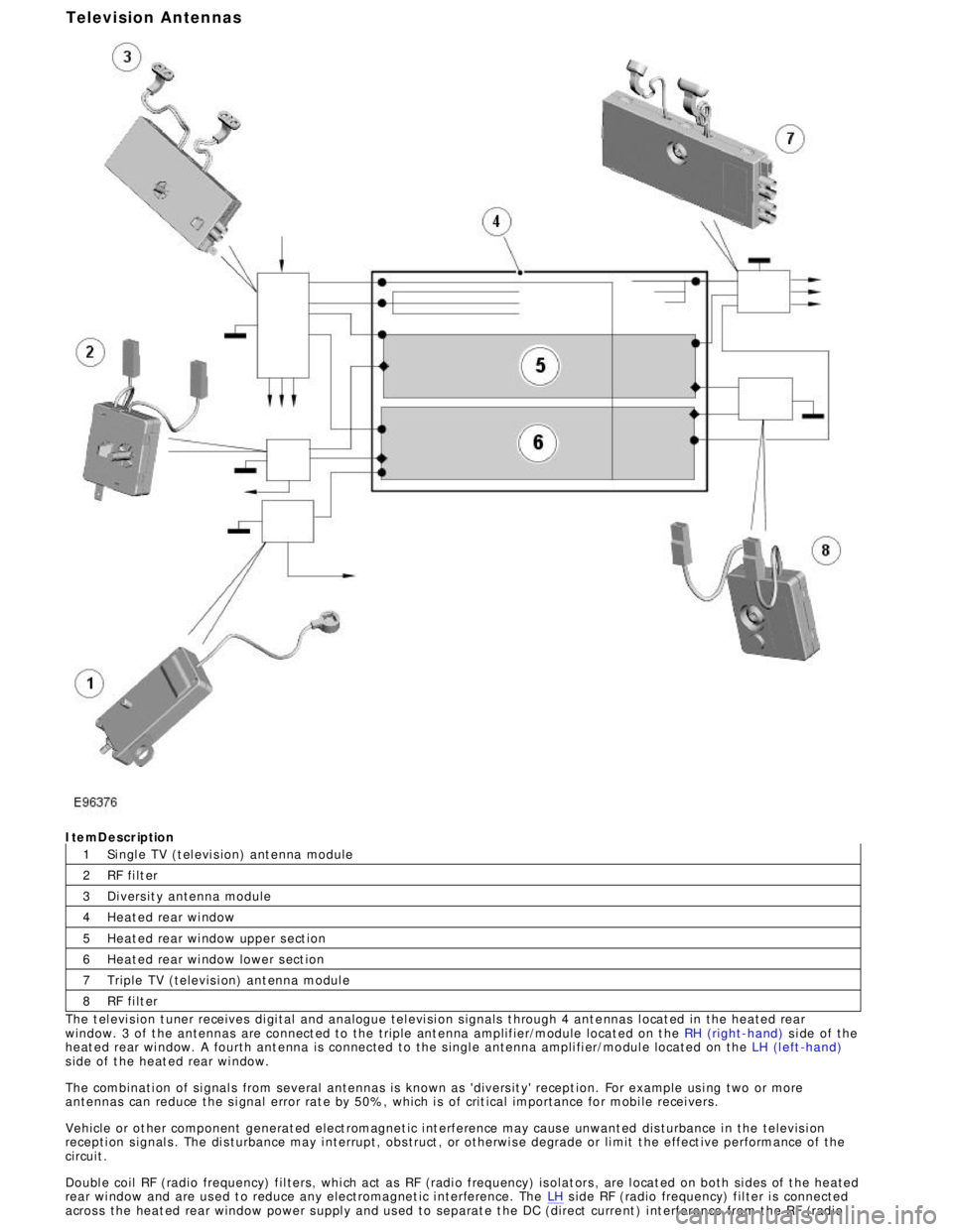
8ItemDescription
Si ngl e TV (t el evi s ion) ant enna module
RF fi lt er
Di vers it y antenna module
Heat ed rear wi ndow
Heat ed rear wi ndow upper s ect ion
Heat ed rear wi ndow lower s ect ion
Triple TV (televis i on) ant enna modul e
RF fi lt er
The t el evi s ion t uner receives di gi tal and analogue tel evi si on s ignals t hrough 4 ant e nnas l ocat ed in the heated rear
window. 3 of t he antennas are connect ed to the triple ant enna amplifier/module locat ed on t he RH (right-hand) s i de of the
heat ed rear wi ndow. A fourth ant enna is connected to the s ingl e antenna ampli fi er/mo dul e located on the LH (l eft -hand)
s ide of t he heat ed rear wi ndow.
The combinati on of si gnal s from several antennas is known as 'divers it y' recept ion. For example us i ng two or more
antennas can reduce the s i gnal error rat e by 50%, which i s of crit ical importance for mobi le recei vers.
Vehicle or ot her component generat ed elect romagnet ic i nt erference may caus e unwant ed dis turbance i n the televis i on
recepti on s ignal s . The di s turbance may i nterrupt, obs truct , or otherwi s e degrade or li mit t he effect ive performance of t he
circuit .
Doubl e coil RF (radio frequency) fil ters, whi ch act as RF (radi o frequency) is olat ors , are l ocat ed on both si des of t he heated
rear wi ndow and are us ed t o reduce any electromagnet ic i nterference. The LH s ide RF (radio frequency) fil ter i s connected
acros s the heat ed rear window power s uppl y and us ed to separat e t he DC (direct curre nt ) i nt erference from t he RF (radioTelevision Antennas
Page 1988 of 3039
1
2
3 frequency) si gnal s. The pos it ive fil ter i s pres ent on al l vehi cl e t ypes and market s .
The ri ght hand s i de doubl e coi l RF (radio frequency) filt er is onl y used in conjunct ion wit h t he tel evi si on antenna modules
and is connect ed acros s the heat ed rear wi ndow ground ci rcuit . If a tel evi si on s ys t e m i s not fi tt ed a fil ter i s used whi ch is
li nked di rectl y t o ground.
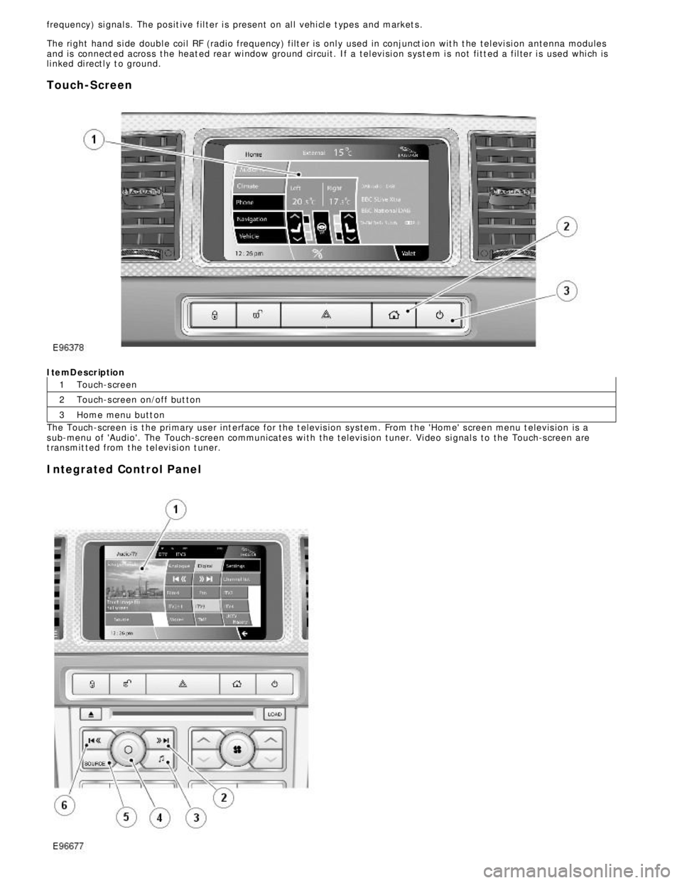
Touch-ScreenItemDescription
Touch-s creen
Touch-s creen on/off but ton
Home menu butt on
The Touch-screen i s t he pri mary us er int erface for the t elevis ion sys tem. From t he 'Home' s creen menu t elevis ion is a
s ub-menu of 'Audio'. The Touch-s creen communicates wi th the t elevis ion tuner. Vi deo si gnal s to the Touch-s creen are
t ransmit ted from t he tel evi si on t uner.
Integrated Control Panel
Page 2124 of 3039

The battery backed sounder is disconnected (partial trigger only).
The vehicle battery is disconnected on a vehicle fitted with a battery backed sounder (partial trigger only).
The inclination sensor detects a change in vehicle attitude.
The intrusion detection module detects movement within the cabin.
Door Modules Component Description
The door modules provide the interface between the door latch-motors, the door latch-switches and the CJB. The door modules
provide door switch status information and enable the door latch-motors on request from the CJB or the keyless vehicle
module.
Keyless Vehicle Module
The keyless vehicle module interfaces with the Central locking, Radio Frequency (RF) receiver and collects RF signal information
which is transmitted from the Smart Key. This information is translated into commands which are passed on the medium speed
CAN bus to the:
CJB,
RJB,
door modules, and
instrument cluster.
The keyless vehicle module also monitors:
2 interior antennae,
1 luggage compartment antenna,
a rear bumper antenna, and
4 door handle antennae if the passive entry system is fitted.
On vehicles with passive entry, the additional fast latch motors are controlled via the keyless vehicle module and the locking
status is passed to the CJB on the medium speed CAN bus.
Instrument Cluster
The instrument cluster controls the alarm indicator, and in conjunction with the ECM (engine control module), the engine
immobilization. The ECM controls the engine crank and fuel functions and the instrument cluster processes the valid
transponder information.
Alarm Indicator
The alarm indicator is a LED (light emitting diode) located in the body of the sunload/light sensor. When the ignition is off the
indicator gives a visual indication of the active anti-theft system to show if the alarm system is active or not active. Operation
of the alarm indicator is controlled by the instrument cluster which varies the flash rate of the LED to indicate the system
status of the alarm and the immobilization systems.
When the ignition is on, the indicator provides a visual indication of the status of the passive anti-theft (engine
immobilization) system. If the immobilization system is operating correctly, the LED will be illuminated for 3 seconds at
ignition on and then extinguish. If a fault exists in the immobilization system, the LED will be either permanently illuminated
or flashing for 60 seconds. This indicates that a fault exists and fault code has been recorded. After the 60 second period the
LED will flash at different frequencies which indicate the nature of the fault.
Refer to: Anti-Theft - Passive (419-01B Anti-Theft - Passive, Description and Operation).
Passive Anti-Theft Horn
The passive anti-theft horn is hardwired to the CJB which activates the horn when the alarm is triggered.
Battery Backed Sounder
Operation of the battery backed sounder is controlled by the CJB on the LIN bus. The sounder is also connected with a
permanent battery supply via the CJB. An integral, rechargeable battery powers the sounder if the battery power supply from
the CJB is interrupted.
Dependant on vehicle, a incitation sensor is incorporated into the battery backed sounder, to monitor vehicle attitude, see
Inclination Sensor.
Inclination Sensor
The CJB monitors the inclination sensor and will activate the alarm system if the vehicle is being raised.
Intrusion Detection Module
The intrusion detection module comprises an ultrasonic sound wave sensor which monitors the vehicle's interior.
The intrusion detection module is activated with volumetric mode which in turn is enabled when the vehicle is double locked.
The vehicle can be locked and alarmed with the module de-activated if a pet is to be left in the vehicle for example by single-
Page 2140 of 3039
Published: 11-May-2011
Anti-Theft - Passive - Anti-Theft - Passive - Component Location
Description and Operation
Component Location
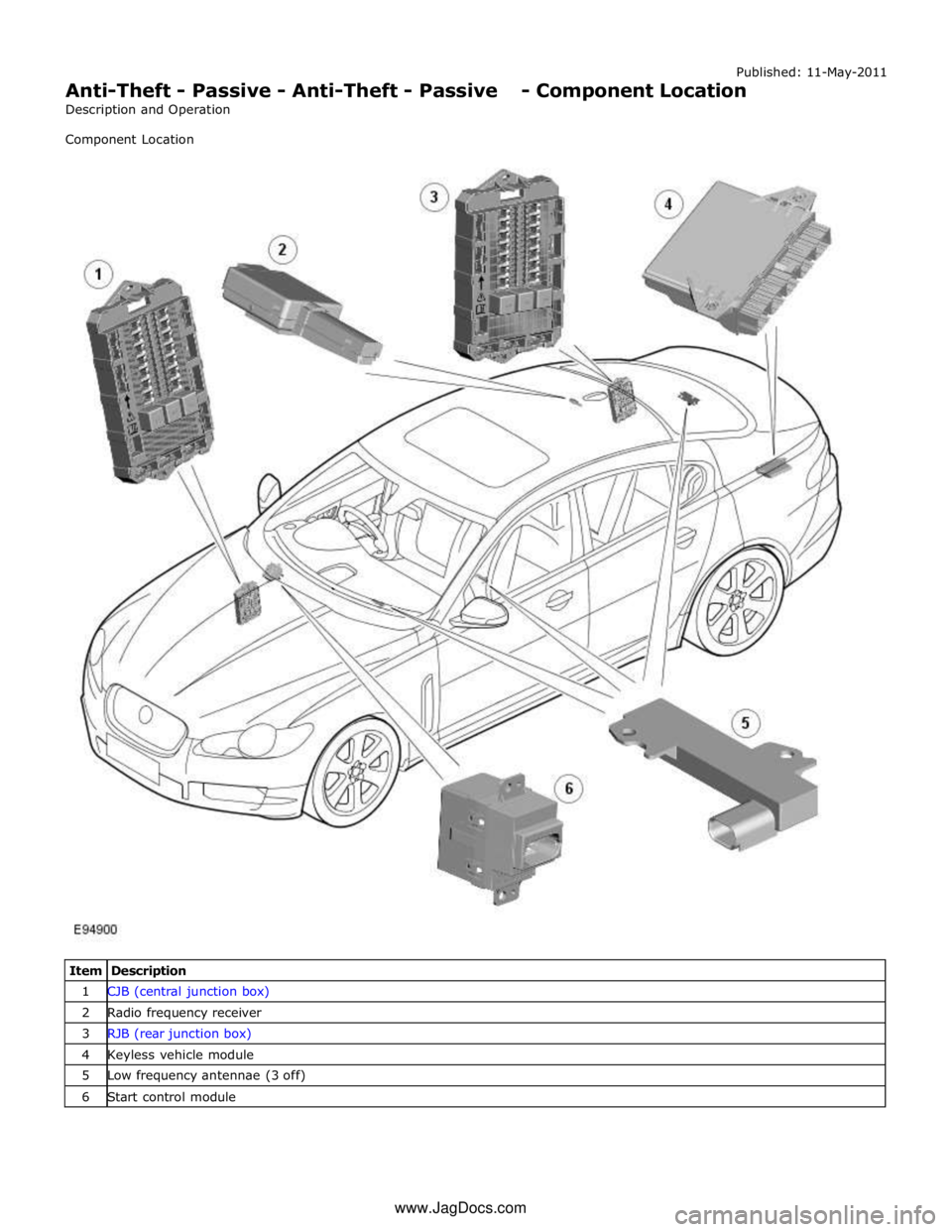
Item Description 1 CJB (central junction box) 2 Radio frequency receiver 3 RJB (rear junction box) 4 Keyless vehicle module 5 Low frequency antennae (3 off) 6 Start control module www.JagDocs.com
Page 2143 of 3039
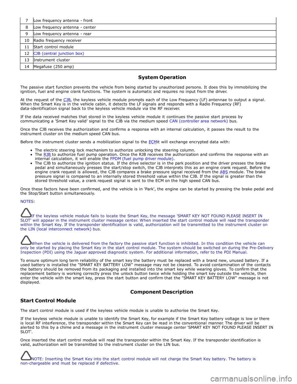
7 Low frequency antenna - front 8 Low frequency antenna - center 9 Low frequency antenna - rear 10 Radio frequency receiver 11 Start control module 12 CJB (central junction box) 13 Instrument cluster 14 Megafuse (250 amp)
System Operation
The passive start function prevents the vehicle from being started by unauthorized persons. It does this by immobilizing the
ignition, fuel and engine crank functions. The system is automatic and requires no input from the driver.
At the request of the CJB, the keyless vehicle module prompts each of the Low Frequency (LF) antennae to output a signal. When the Smart Key is in the vehicle cabin, it detects the LF signals and responds with a Radio Frequency (RF)
data-identification signal back to the keyless vehicle module via the RF receiver.
If the data received matches that stored in the keyless vehicle module it continues the passive start process by
communicating a 'Smart Key valid’ signal to the CJB via the medium speed CAN (controller area network) bus.
Once the CJB receives the authorization and confirms a response with an internal calculation, it passes the result to the
instrument cluster on the medium speed CAN bus.
Before the instrument cluster sends a mobilization signal to the ECMit will exchange encrypted data with: The electric steering lock mechanism to authorize unlocking the steering column.
The RJB to authorize fuel pump operation. Once the RJB receives the authorization and confirms the response with an internal calculation, it will enable the FPDM (fuel pump driver module).
The CJB to authorize the ignition status. If the drive selector is in the park position and the driver presses the brake
pedal and simultaneously presses the start/stop switch, the CJB interprets this as an engine crank request. Before the
engine crank request is allowed, the CJB compares a brake pressure signal received from the ABS module. The brake pressure signal is compared to an internally stored threshold value within the CJB. If the signal is greater than the
stored threshold value, a crank request signal is sent to the ECM on the high speed CAN bus.
Once these factors have been confirmed, and the vehicle is in 'Park', the engine can be started by pressing the brake pedal and
the Stop/Start button simultaneously.
NOTES:
If the keyless vehicle module fails to locate the Smart Key, the message 'SMART KEY NOT FOUND PLEASE INSERT IN
SLOT' will appear in the instrument cluster message center. When inserted the start control module will read the transponder
within the Smart Key. If the transponder identification is valid, authorization will be transmitted to the instrument cluster on
the LIN (local interconnect network) bus.
When the vehicle is delivered from the factory the passive start function is inhibited. In this condition the vehicle can
only be started by placing the Smart Key in the start control module. The system should be switched on during the Pre-Delivery
Inspection (PDI) using the Jaguar approved diagnostic system. For additional information, refer to the PDI Manual.
To ensure optimum long term reliability of the smart key the battery must be replaced with a brand new, unused battery. If a
used battery is installed the "SMART KEY BATTERY LOW" message may not be cleared. To avoid contamination of the contacts
the battery should be removed from its packaging and installed into the smart key while wearing gloves. To confirm that the
replacement battery is working correctly press the unlock button twice while holding the smart key outside the vehicle, then
enter the vehicle with the smart key, press the start button and confirm that the "SMART KEY BATTERY LOW" message is not
displayed.
Start Control Module Component Description
The start control module is used if the keyless vehicle module is unable to authorise the Smart Key.
If the keyless vehicle module is unable to identify the Smart Key, for example if the Smart Key battery voltage is low or there
is local RF interference, the transponder within the Smart Key can be read in the conventional manner. The driver will be
alerted to this by a chime and a message in the instrument cluster message center 'SMART KEY NOT FOUND PLEASE INSERT IN
SLOT'.
Once inserted the start control module will read the transponder within the Smart Key. If the transponder identification is
valid, authorization will be transmitted to the instrument cluster on the LIN bus.
NOTE: Inserting the Smart Key into the start control module will not charge the Smart Key battery. The battery is
non-chargeable and must be replaced if defective.
Page 2144 of 3039

A message 'REMOVE SMART KEY' will be displayed if the Smart Key is still in the start control module and the driver's door is
opened.
Low Frequency Antenna
Three Low Frequency (LF) antennae for the passive start system are positioned in specific locations in the vehicle; refer to
Component Location graphic.
NOTE: On vehicles with the passive entry system, five additional antennae are used; one integrated into the rear bumper
and one in each door handle assembly. These are only used by the passive entry system and have no function in the passive
start system.
The keyless vehicle module transmits an LF signal via the antennae which is received by the Smart Key. The Smart Key then
responds by transmitting a Radio Frequency (RF) signal which is received by the RF receiver and passed to the keyless vehicle
module for authorization.
Keyless Vehicle Module
The keyless vehicle module controls signal transmissions to and from the Smart Key and provides authorization to allow the
vehicle to be started. The module has a medium speed CAN connection to the CJB for authorizing vehicle starting.
Radio Frequency Receiver
The Radio Frequency (RF) receiver transmission is received from the Smart Key to enable key identification.
Page 2488 of 3039
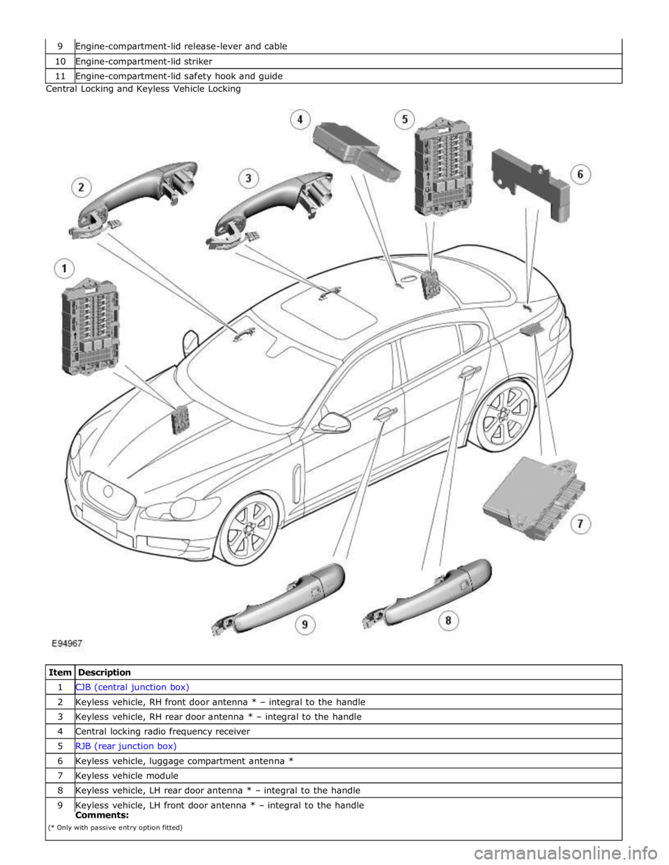
10 Engine-compartment-lid striker 11 Engine-compartment-lid safety hook and guide Central Locking and Keyless Vehicle Locking
Item Description 1 CJB (central junction box) 2 Keyless vehicle, RH front door antenna * – integral to the handle 3 Keyless vehicle, RH rear door antenna * – integral to the handle 4 Central locking radio frequency receiver 5 RJB (rear junction box) 6 Keyless vehicle, luggage compartment antenna * 7 Keyless vehicle module 8 Keyless vehicle, LH rear door antenna * – integral to the handle 9 Keyless vehicle, LH front door antenna * – integral to the handle Comments:
(* Only with passive entry option fitted)
Page 2493 of 3039

Item Description Note: A = Hardwired; N = Medium speed CAN 1 Battery 2 Megafuse (250 A) 3 CJB 4 Radio frequency receiver 5 Keylesss vehicle module 6 Door handle, lock/unlock switch and antenna - front passenger 7 Door latch, fast latch - front passenger 8 Door latch, fast latch - RH rear passenger 9 Door handle, lock/unlock switch and antenna - RH rear passenger 10 Door latch, fast latch - LH rear passenger 11 Door handle, lock/unlock switch and antenna - LH rear passenger 12 Door latch, fast latch - driver door 13 Door handle, lock/unlock switch and antenna - driver door
System Operation
The hinged panels are secured with latches and strikers. A remotely operated central locking system controls the locking and
unlocking of the door and luggage compartment latches. A radio frequency Smart Key allows the vehicle to be locked and
unlocked by pressing the appropriate handset buttons. Two levels of central locking system are available: remote central
locking and an optional passive entry system.
The passive entry and associated passive start system allows the driver to unlock and start the vehicle without using a vehicle
key in a door-lock or ignition switch. The passive entry system is an optional fitment while the passive start system is a
standard fitment on all vehicles. The passive start system is combined with the passive anti-theft immobilization system.
Refer to: Anti-Theft - Passive (419-01B Anti-Theft - Passive, Description and Operation).
Emergency access to the vehicle is provided by two concealed key barrels: one located in the front left-hand door handle and
one located on the underside of the luggage compartment lid finisher. An emergency, removable key blade is fitted into the
Smart Key.
Operation of either key barrel unlocks the vehicle but does not disarm the alarm system. The key barrels in the door and
luggage compartment lid are concealed by a plastic cover which can be removed by inserting the blade of the emergency key
into a slot in the cover.
Locking and unlocking conditions using the emergency key in the door key barrel:
If the alarm is not armed the vehicle can be centrally unlocked.
If the alarm is armed the door only can be opened and the alarm will be triggered.
The vehicle cannot be double locked or the alarm system armed using the emergency key.
The vehicle can be centrally locked and unlocked from inside using the interior handle release levers on the front doors only.
Central locking and unlocking can also be performed using lock and unlock buttons on the vehicle's fascia. The driver can select
locking options, single point entry or drive away locking for example, from a menu available on the touch screen.
Central Locking – Radio Frequency Remote System
The radio frequency central locking system, provides locking and unlocking of the vehicle from inside and outside of the
vehicle. The system is operated using buttons on the Smart Key, which transmits radio frequency signals to the central locking
radio frequency receiver.
The system provides additional security by double-locking the doors from outside the vehicle if the lock button, on the Smart
Key, is pressed twice within 3 seconds; this function is not applicable in North American Specification (NAS) and Japanese
markets.
Additional buttons on the Smart Key provide for the convenience operation of the luggage compartment lid release, headlamp
delay and panic alarm functions. A global open or close feature is also available in certain markets using the lock/unlock
buttons.
Passive Entry
On vehicles fitted with the optional passive entry system, the vehicle can be unlocked without the use of a key blade or
pressing buttons on the Smart Key. The Smart Key operates the passive entry system in addition to the passive start system.
Refer to: Anti-Theft - Passive (419-01B Anti-Theft - Passive, Description and Operation).
The passive entry system is controlled by the keyless vehicle module and five low frequency antennas. One antenna located in
each door handle and one antenna located behind the rear bumper cover.
When a vehicle door handle is pulled to the first five-percent of its travel and the Smart Key is within one meter of the handle;
the Smart Key receives the low-frequency signal transmitted from the keyless vehicle module. The Smart Key responds with a
radio frequency transmission of its authorization code. The radio frequency signal is received by the central locking radio-
frequency receiver and passed to the keyless vehicle module which checks and approves the code as valid. Once the handle is