2010 JAGUAR XFR fuel filter
[x] Cancel search: fuel filterPage 1344 of 3039
Published: 11-May-2011
Evaporative Emissions - V8 5.0L Petrol/V8 S/C 5.0L Petrol - Evaporative Emissions - System Operation and Component Description
Description and Operation
System Operation DIAGNOSTIC MODULE - TANK LEAKAGE PUMP (NAS ONLY)
To check the fuel tank and the EVAP (evaporative emission) system for leaks, the ECM (engine control module) operates the
DMTL pump and monitors the current draw. Initially, the ECM establishes a reference current by pumping air through the reference orifice and back to atmosphere. Once the reference current is determined, the ECM closes the change-over valve, which seals the EVAP system. The EVAP canister purge valve remains de-energized and is therefore closed. The output from the air pump is diverted from the reference orifice and into the EVAP system.
When the change-over valve is closed, the load on the air pump falls to zero. Providing there are no leaks, the air pump will
begin to pressurize the EVAP system and the load and current draw in the pump increases. By monitoring the rate and level of the current increase, the ECM can determine if there is a leak in the EVAP system.
During normal vehicle operation, 15 seconds after the engine has started, the ECM energizes the heating element in the pump to prevent condensation formation and possible incorrect readings. The heater remains energized until either the engine and
ignition are off (if no DMTL test is running) or until after the DMTL test is completed.
Leaks are classified as:
Minor - equivalent to a hole diameter of 0.5 to 1.0 mm (0.02 to 0.04 in.).
Major - equivalent to a hole diameter of 1.0 mm (0.04 in.) or greater.
The ECM performs a check for major leaks each time the ignition is switched off, providing the following conditions are met: The vehicle speed is zero.
The engine speed is zero.
The atmospheric pressure is above 70 kPa (10.15 lbf/in2
), i.e. the altitude is less than approximately 3047 m (10000
feet).
The ambient temperature is between 0 and 40 °C (32 and 104 °F).
The EVAP canister vapor concentration factor is 5 or less (where 0 is no fuel vapor, 1 is stoichiometric fuel vapor and greater than 1 is rich fuel vapor).
The fuel tank level is valid and between 15 and 85% of nominal capacity.
The engine running time during the previous cycle was more than 10 minutes.
The battery voltage is between 10 and 15 volts.
The last engine off time was more than 180 minutes.
No errors are detected with the EVAP components, the ambient air temperature and the fuel level.
NOTE: A leak test can be performed using a Jaguar recognized diagnostic tool. This overrides the above conditions and is
useful for checking correct system and component operation.
The ECM performs a check for minor leaks after every 2nd major leak check.
When the leak check is complete, the ECM stops the DMTL pump and opens (de-energizes) the change-over valve.
If the fuel filler cap is opened or refueling is detected during the leak check, by a sudden drop in the current draw or a rise in
the fuel level, the ECM aborts the leak check.
If a leak is detected during the check, the ECM stores an appropriate fault code in its memory. If a leak is detected on two consecutive checks, the ECM illuminates the MIL (malfunction indicator lamp) in the instrument cluster on the next drive cycle. The duration of a leak check can be between 60 and 900 seconds depending on the results and fuel tank level.
EVAP CANISTER PURGE VALVE
The ECM waits until the engine is running above 55 °C (131 °F) coolant temperature with closed loop fuel operational before the purging process is activated. Under these conditions the engine should be running smoothly with no warm up enrichment.
The EVAP canister purge valve duty (and flow) is initially ramped slowly because the vapor concentration is unknown (a sudden increase in purge could cause unstable engine running or cause it to stall due to an extremely "rich" air/fuel mixture). The
concentration is then determined from the amount of adjustment that the closed loop fueling is required to make to achieve
the target AFR (air fuel ratio). Once the concentration has been determined, the purge flow can be increased rapidly and the
injected fuel can be pro-actively adjusted to compensate for the known purge vapor and the target AIR control is maintained.
When the purging process is active, fresh air is drawn into the EVAP canister via the DMTL filter and pump on NAS vehicles, or via the vent port on the EVAP canister of non NAS vehicles.
Page 1345 of 3039
Component Description DIAGNOSTIC MODULE - TANK LEAKAGE PUMP (NAS ONLY)
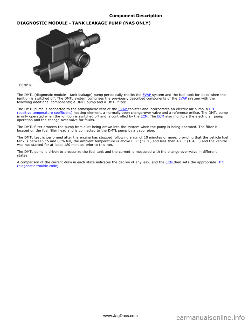
The DMTL (diagnostic module - tank leakage) pump periodically checks the EVAP system and the fuel tank for leaks when the ignition is switched off. The DMTL system comprises the previously described components of the EVAP system with the following additional components; a DMTL pump and a DMTL filter.
The DMTL pump is connected to the atmospheric vent of the EVAP canister and incorporates an electric air pump, a PTC (positive temperature coefficient) heating element, a normally open change-over valve and a reference orifice. The DMTL pump
is only operated when the ignition is switched off and is controlled by the ECM. The ECM also monitors the electric air pump operation and the change-over valve for faults.
The DMTL filter protects the pump from dust being drawn into the system when the pump is being operated. The filter is
located on the fuel filler head and is connected to the DMTL pump by a vapor pipe.
The DMTL test is performed after the engine has stopped following a run of 10 minutes or more, providing that the vehicle fuel
tank is between 15 and 85% full, the ambient temperature is above 0 °C (32 °F) and less than 40 °C (104 °F) and the vehicle
was not started for at least 180 minutes prior to this run.
The DMTL pump is driven to pressurize the fuel tank and the current is measured with the change-over valve in different
states.
A comparison of the current draw in each state indicates the degree of any leak, and the ECM then sets the appropriate DTC (diagnostic trouble code).
www.JagDocs.com
Page 1580 of 3039
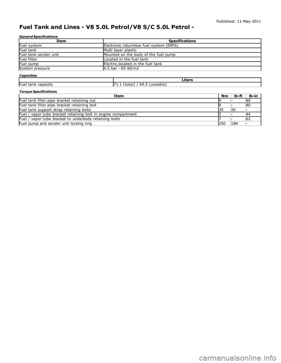
Fuel system Electronic returnless fuel system (ERFS) Fuel tank Multi layer plastic Fuel tank sender unit Mounted on the body of the fuel pump Fuel filter Located in the fuel tank Fuel pump Electric,located in the fuel tank System pressure 4.5 bar - 65 lbf/in2 Capacities Liters Fuel tank capacity 71.1 (total) / 69.5 (useable) Torque Specifications
Item Nm lb-ft lb-in Fuel tank filler pipe bracket retaining nut 9 - 80 Fuel tank filler pipe bracket retaining bolt 9 - 80 Fuel tank support strap retaining bolts 35 26 - Fuel / vapor tube bracket retaining bolt in engine compartment 5 - 44 Fuel / vapor tube bracket to underbody retaining bolts 7 - 62 Fuel pump and sender unit locking ring 250 184 -
Page 1583 of 3039

8 Fuel tank 9 Fuel filler hose 10 FPDM 11 Anti-trickle valve 12 Fuel filler cap and lanyard 13 DMTL filter 14 Fuel filler pipe 15 Charcoal canister 16 DMTL pump 17 Pipe - EVAP charcoal canister to purge valve
Page 1586 of 3039
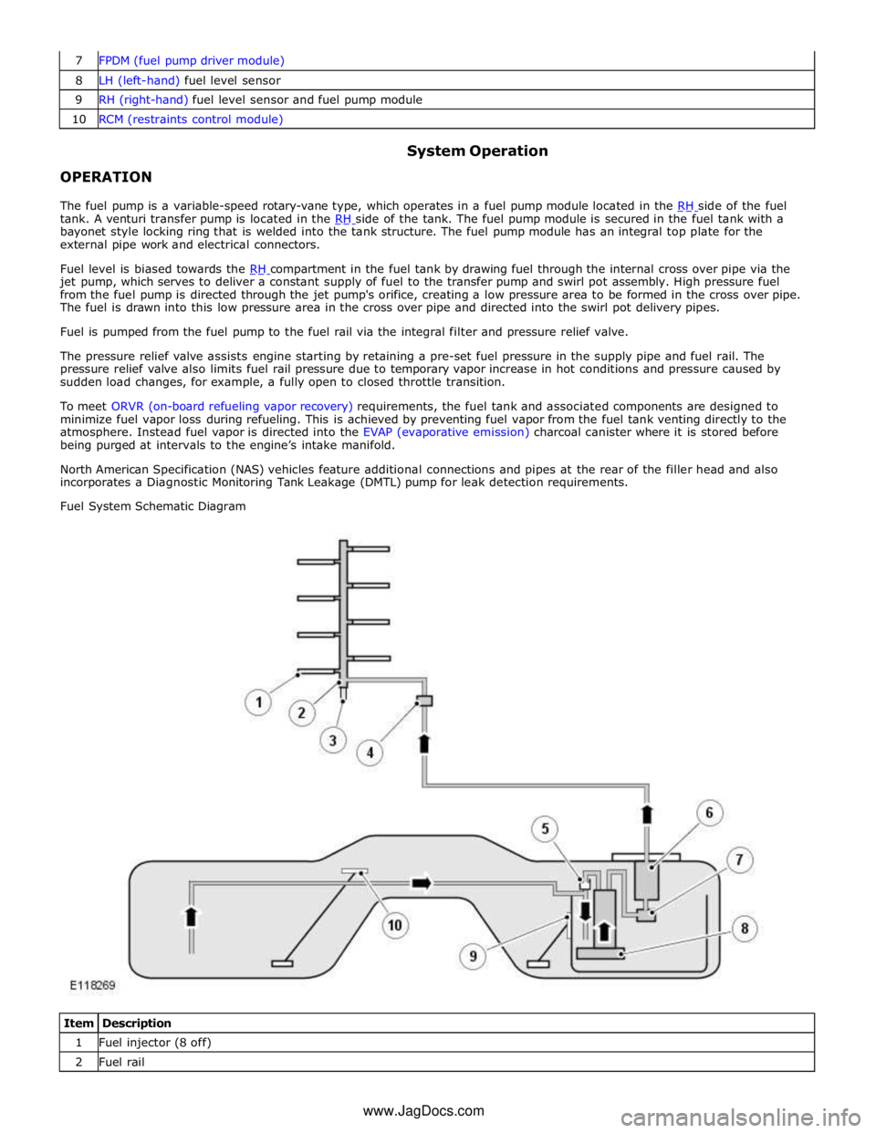
8 LH (left-hand) fuel level sensor 9 RH (right-hand) fuel level sensor and fuel pump module 10 RCM (restraints control module)
OPERATION System Operation
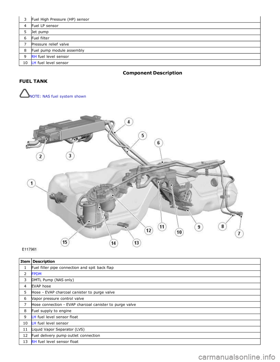
The fuel pump is a variable-speed rotary-vane type, which operates in a fuel pump module located in the RH side of the fuel tank. A venturi transfer pump is located in the RH side of the tank. The fuel pump module is secured in the fuel tank with a bayonet style locking ring that is welded into the tank structure. The fuel pump module has an integral top plate for the
external pipe work and electrical connectors.
Fuel level is biased towards the RH compartment in the fuel tank by drawing fuel through the internal cross over pipe via the jet pump, which serves to deliver a constant supply of fuel to the transfer pump and swirl pot assembly. High pressure fuel
from the fuel pump is directed through the jet pump's orifice, creating a low pressure area to be formed in the cross over pipe.
The fuel is drawn into this low pressure area in the cross over pipe and directed into the swirl pot delivery pipes.
Fuel is pumped from the fuel pump to the fuel rail via the integral filter and pressure relief valve.
The pressure relief valve assists engine starting by retaining a pre-set fuel pressure in the supply pipe and fuel rail. The
pressure relief valve also limits fuel rail pressure due to temporary vapor increase in hot conditions and pressure caused by
sudden load changes, for example, a fully open to closed throttle transition.
To meet ORVR (on-board refueling vapor recovery) requirements, the fuel tank and associated components are designed to
minimize fuel vapor loss during refueling. This is achieved by preventing fuel vapor from the fuel tank venting directly to the
atmosphere. Instead fuel vapor is directed into the EVAP (evaporative emission) charcoal canister where it is stored before
being purged at intervals to the engine’s intake manifold.
North American Specification (NAS) vehicles feature additional connections and pipes at the rear of the filler head and also
incorporates a Diagnostic Monitoring Tank Leakage (DMTL) pump for leak detection requirements.
Fuel System Schematic Diagram
Item Description 1 Fuel injector (8 off) 2 Fuel rail www.JagDocs.com
Page 1587 of 3039
3 Fuel High Pressure (HP) sensor 4 Fuel LP sensor 5 Jet pump 6 Fuel filter 7 Pressure relief valve 8 Fuel pump module assembly 9 RH fuel level sensor 10 LH fuel level sensor
FUEL TANK
NOTE: NAS fuel system shown Component Description
Item Description 1 Fuel filler pipe connection and spit back flap 2 FPDM 3 DMTL Pump (NAS only) 4 EVAP hose 5 Hose - EVAP charcoal canister to purge valve 6 Vapor pressure control valve 7 Hose connection - EVAP charcoal canister to purge valve 8 Fuel supply to engine 9 LH fuel level sensor float 10 LH fuel level sensor 11 Liquid Vapor Separator (LVS) 12 Fuel delivery pump outlet connection 13 RH fuel level sensor float
Page 1589 of 3039
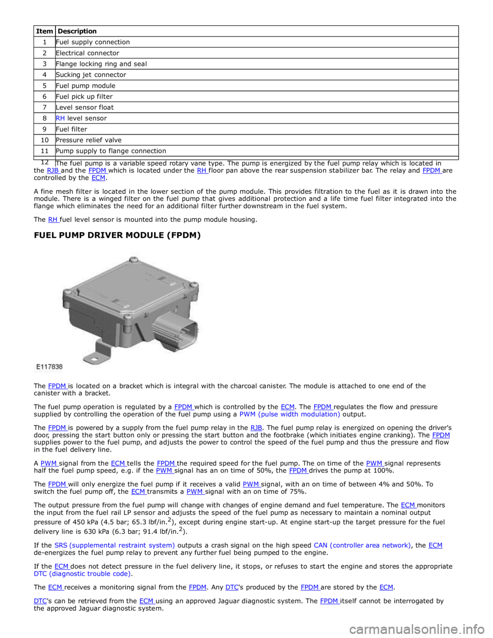
1 Fuel supply connection 2 Electrical connector 3 Flange locking ring and seal 4 Sucking jet connector 5 Fuel pump module 6 Fuel pick up filter 7 Level sensor float 8 RH level sensor 9 Fuel filter 10 Pressure relief valve 11 Pump supply to flange connection 12 The fuel pump is a variable speed rotary vane type. The pump is energized by the fuel pump relay which is located in the RJB and the FPDM which is located under the RH floor pan above the rear suspension stabilizer bar. The relay and FPDM are controlled by the ECM.
A fine mesh filter is located in the lower section of the pump module. This provides filtration to the fuel as it is drawn into the
module. There is a winged filter on the fuel pump that gives additional protection and a life time fuel filter integrated into the
flange which eliminates the need for an additional filter further downstream in the fuel system.
The RH fuel level sensor is mounted into the pump module housing.
FUEL PUMP DRIVER MODULE (FPDM)
The FPDM is located on a bracket which is integral with the charcoal canister. The module is attached to one end of the canister with a bracket.
The fuel pump operation is regulated by a FPDM which is controlled by the ECM. The FPDM regulates the flow and pressure supplied by controlling the operation of the fuel pump using a PWM (pulse width modulation) output.
The FPDM is powered by a supply from the fuel pump relay in the RJB. The fuel pump relay is energized on opening the driver's door, pressing the start button only or pressing the start button and the footbrake (which initiates engine cranking). The FPDM supplies power to the fuel pump, and adjusts the power to control the speed of the fuel pump and thus the pressure and flow
in the fuel delivery line.
A PWM signal from the ECM tells the FPDM the required speed for the fuel pump. The on time of the PWM signal represents half the fuel pump speed, e.g. if the PWM signal has an on time of 50%, the FPDM drives the pump at 100%.
The FPDM will only energize the fuel pump if it receives a valid PWM signal, with an on time of between 4% and 50%. To switch the fuel pump off, the ECM transmits a PWM signal with an on time of 75%.
The output pressure from the fuel pump will change with changes of engine demand and fuel temperature. The ECM monitors the input from the fuel rail LP sensor and adjusts the speed of the fuel pump as necessary to maintain a nominal output
pressure of 450 kPa (4.5 bar; 65.3 lbf/in.2
), except during engine start-up. At engine start-up the target pressure for the fuel
delivery line is 630 kPa (6.3 bar; 91.4 lbf/in.2
).
If the SRS (supplemental restraint system) outputs a crash signal on the high speed CAN (controller area network), the ECM de-energizes the fuel pump relay to prevent any further fuel being pumped to the engine.
If the ECM does not detect pressure in the fuel delivery line, it stops, or refuses to start the engine and stores the appropriate DTC (diagnostic trouble code).
The ECM receives a monitoring signal from the FPDM. Any DTC's produced by the FPDM are stored by the ECM.
DTC's can be retrieved from the ECM using an approved Jaguar diagnostic system. The FPDM itself cannot be interrogated by the approved Jaguar diagnostic system.
Page 1593 of 3039
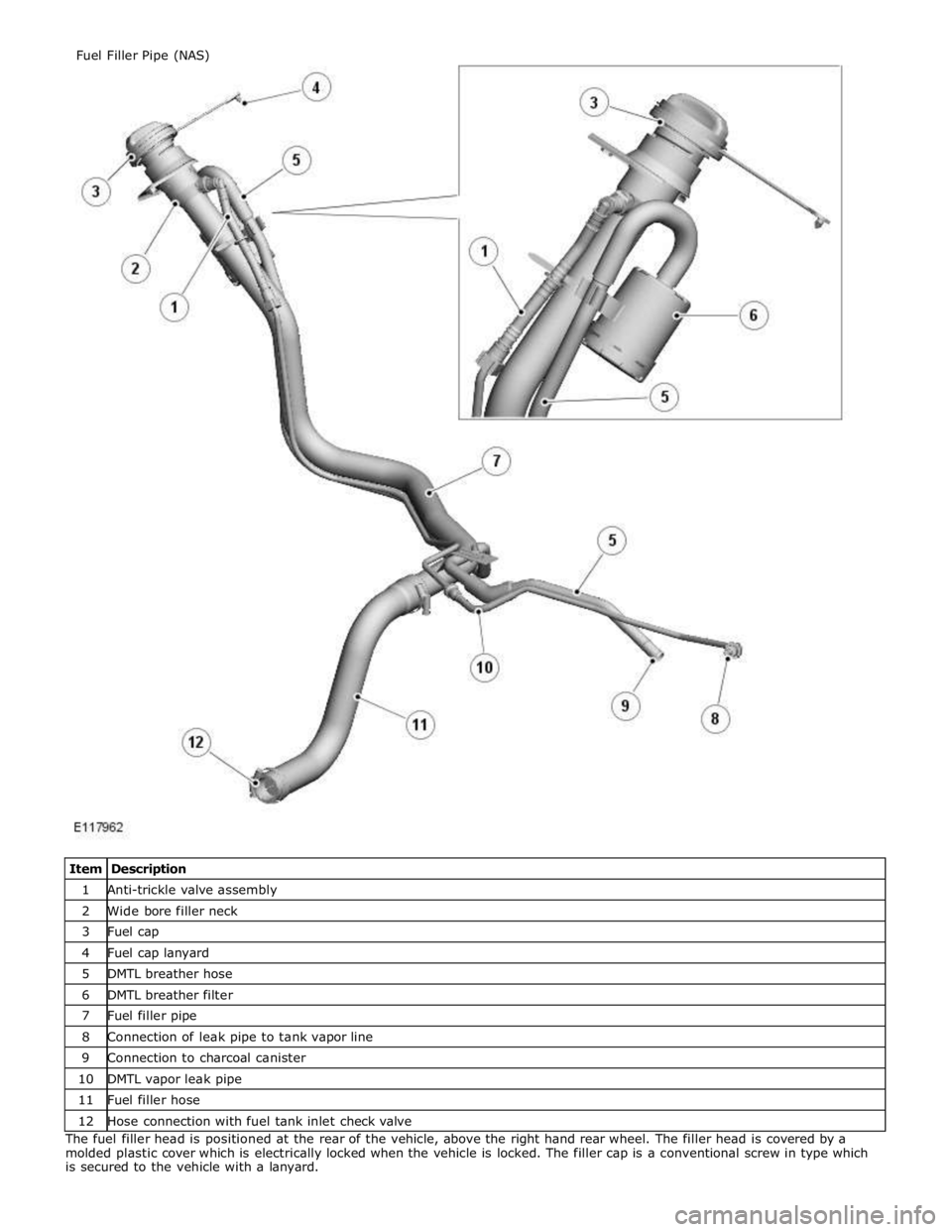
1 Anti-trickle valve assembly 2 Wide bore filler neck 3 Fuel cap 4 Fuel cap lanyard 5 DMTL breather hose 6 DMTL breather filter 7 Fuel filler pipe 8 Connection of leak pipe to tank vapor line 9 Connection to charcoal canister 10 DMTL vapor leak pipe 11 Fuel filler hose 12 Hose connection with fuel tank inlet check valve The fuel filler head is positioned at the rear of the vehicle, above the right hand rear wheel. The filler head is covered by a
molded plastic cover which is electrically locked when the vehicle is locked. The filler cap is a conventional screw in type which
is secured to the vehicle with a lanyard. Fuel Filler Pipe (NAS)