Page 1388 of 3039
Installation 5. WARNING: Fluid loss is unavoidable, use absorbent
cloth or a container to collect the fluid.
CAUTION: Engine coolant will damage the paint
finished surfaces. If spilt, immediately remove the coolant
and clean the area with water.
Lift the tang and rotate the engine coolant temperature
(ECT) sensor counter clockwise.
1. To install, reverse the removal procedure.
Page 1389 of 3039
Published: 11-May-2011
Electronic Engine Controls - V8 S/C 5.0L Petrol - Engine Oil Level Sensor
Removal and Installation
Removal
NOTE: Removal steps in this procedure may contain installation details.
1. WARNING: Do not work on or under a vehicle supported only by a jack.
Always support the vehicle on safety stands.
Raise and support the vehicle.
2. Refer to: Air Deflector (501-02 Front End Body Panels, Removal and Installation).
3. Refer to: Engine Oil Draining and Filling (303-01D Engine - V8 S/C 5.0L Petrol, General Procedures).
Installation
4. CAUTION: Be prepared to collect escaping fluids.
Torque: 11 Nm
1. CAUTION: A new O-ring seal is to be installed.
To install, reverse the removal procedure.
Page 1390 of 3039
Published: 11-May-2011
Electronic Engine Controls - V8 S/C 5.0L Petrol - Front Knock Sensor (KS) LH
Removal and Installation
Removal
NOTE: Removal steps in this procedure may contain installation details.
1. Refer to: Battery Disconnect and Connect (414-01 Battery, Mounting and Cables, General Procedures).
2. WARNING: Do not work on or under a vehicle supported only by a jack.
Always support the vehicle on safety stands.
Raise and support the vehicle.
3. Refer to: Supercharger (303-12D Intake Air Distribution and Filtering - V8 S/C 5.0L Petrol, Removal and Installation).
Installation
4. Torque: 20 Nm
1. To install, reverse the removal procedure.
Page 1391 of 3039
Published: 11-May-2011
Electronic Engine Controls - V8 S/C 5.0L Petrol - Front Knock Sensor (KS) RH
Removal and Installation
Removal
NOTE: Removal steps in this procedure may contain installation details.
1. Refer to: Battery Disconnect and Connect (414-01 Battery, Mounting and Cables, General Procedures).
2. WARNING: Do not work on or under a vehicle supported only by a jack.
Always support the vehicle on safety stands.
Raise and support the vehicle.
3. Refer to: Supercharger (303-12D Intake Air Distribution and Filtering - V8 S/C 5.0L Petrol, Removal and Installation).
Installation
4. Torque: 20 Nm
1. To install, reverse the removal procedure. www.JagDocs.com
Page 1392 of 3039

Published: 11-May-2011
Electronic Engine Controls - V8 S/C 5.0L Petrol - Fuel Rail Pressure (FRP)
Sensor
Removal and Installation
Removal
NOTE: Removal steps in this procedure may contain installation details.
1. Refer to: Fuel System Pressure Release - V8 5.0L Petrol/V8 S/C 5.0L Petrol (310-00 Fuel System - General Information, General Procedures).
2. Disconnect the battery ground cable.
Refer to: Battery Disconnect and Connect (414-01 Battery, Mounting and Cables, General Procedures).
3. Refer to: Cowl Vent Screen (501-02 Front End Body Panels, Removal and Installation).
4. Refer to: Secondary Bulkhead Panel RH - TDV6 3.0L Diesel /V8 5.0L Petrol/V8 S/C 5.0L Petrol (501-02 Front End Body Panels, Removal and Installation).
5. Refer to: Secondary Bulkhead Panel LH - TDV6 3.0L Diesel /V8 5.0L Petrol/V8 S/C 5.0L Petrol (501-02 Front End Body Panels, Removal and Installation).
6. Refer to: Engine Cover - V8 5.0L Petrol/V8 S/C 5.0L Petrol (501-05 Interior Trim and Ornamentation, Removal and Installation).
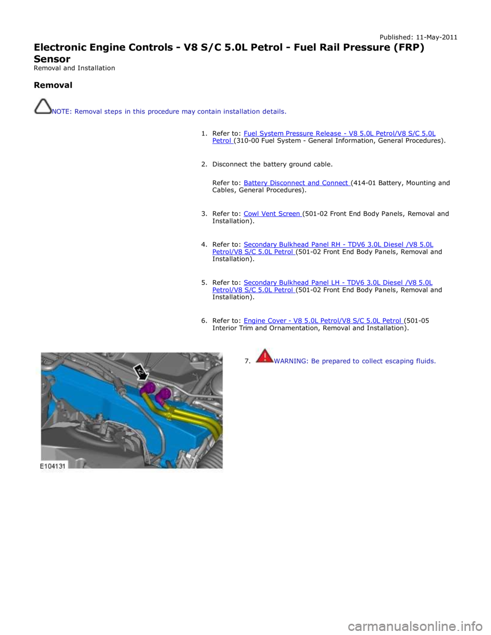
7. WARNING: Be prepared to collect escaping fluids.
Page 1394 of 3039
Published: 11-May-2011
Electronic Engine Controls - V8 S/C 5.0L Petrol - Heated Oxygen Sensor
(HO2S) LH
Removal and Installation
Removal
NOTE: Removal steps in this procedure may contain installation details.
1. Refer to: Battery Disconnect and Connect (414-01 Battery, Mounting and Cables, General Procedures).
2. WARNING: Do not work on or under a vehicle supported only by a jack.
Always support the vehicle on safety stands.
Raise and support the vehicle.
3. Refer to: Air Deflector (501-02 Front End Body Panels, Removal and Installation).
4. Refer to: Catalytic Converter LH (309-00C Exhaust System - V8 5.0L Petrol/V8 S/C 5.0L Petrol, Removal and Installation).
5. CAUTION: Note the fitted position of the component prior
to removal. 310-121
Wrench, H02S Special Tool(s)
Page 1395 of 3039
Installation 6. CAUTION: Make sure that the mating faces are clean
and free of foreign material.
Special Tool(s): 310-121 Torque: 48 Nm
1. CAUTIONS:
Make sure the anti-seize compound does not contact the HO2S tip.
If accidentally dropped or knocked install a new sensor.
Make sure the HO2S wiring harness is not twisted more than 180
degrees and is not in contact with either the exhaust or driveshaft.
NOTE: If the original sensor is to be installed, apply lubricant
meeting specification ESE-M12A4-A to the thread of the sensor.
To install, reverse the removal procedure.
2. NOTE: For NAS vehicles only.
If required, carry out a long drive cycle.
Refer to: Powertrain Control Module (PCM) Long Drive Cycle Self-Test (303-14D Electronic Engine Controls - V8 S/C 5.0L Petrol, General
Procedures).
Page 1396 of 3039
Published: 11-May-2011
Electronic Engine Controls - V8 S/C 5.0L Petrol - Heated Oxygen Sensor
(HO2S) RH
Removal and Installation
Removal
NOTE: Removal steps in this procedure may contain installation details.
1. Refer to: Battery Disconnect and Connect (414-01 Battery, Mounting and Cables, General Procedures).
2. WARNING: Do not work on or under a vehicle supported only by a jack.
Always support the vehicle on safety stands.
Raise and support the vehicle.
3. Refer to: Air Deflector (501-02 Front End Body Panels, Removal and Installation).
4. Refer to: Catalytic Converter RH (309-00C Exhaust System - V8 5.0L Petrol/V8 S/C 5.0L Petrol, Removal and Installation).
5. CAUTION: Note the fitted position of the component prior
to removal. 310-121
Wrench, H02S Special Tool(s) www.JagDocs.com