Page 2541 of 3039

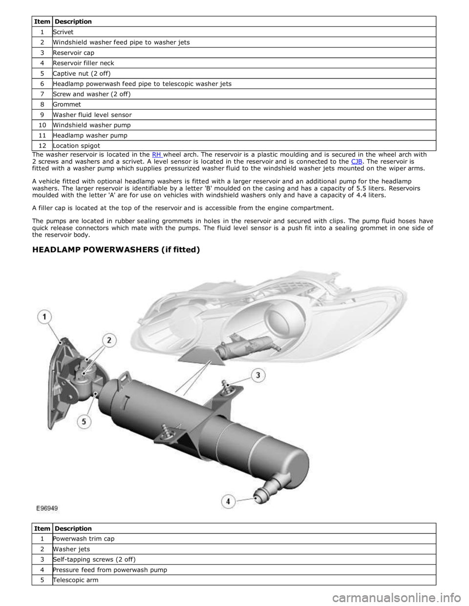
1 Scrivet 2 Windshield washer feed pipe to washer jets 3 Reservoir cap 4 Reservoir filler neck 5 Captive nut (2 off) 6 Headlamp powerwash feed pipe to telescopic washer jets 7 Screw and washer (2 off) 8 Grommet 9 Washer fluid level sensor 10 Windshield washer pump 11 Headlamp washer pump 12 Location spigot The washer reservoir is located in the RH wheel arch. The reservoir is a plastic moulding and is secured in the wheel arch with 2 screws and washers and a scrivet. A level sensor is located in the reservoir and is connected to the CJB. The reservoir is fitted with a washer pump which supplies pressurized washer fluid to the windshield washer jets mounted on the wiper arms.
A vehicle fitted with optional headlamp washers is fitted with a larger reservoir and an additional pump for the headlamp
washers. The larger reservoir is identifiable by a letter 'B' moulded on the casing and has a capacity of 5.5 liters. Reservoirs
moulded with the letter 'A' are for use on vehicles with windshield washers only and have a capacity of 4.4 liters.
A filler cap is located at the top of the reservoir and is accessible from the engine compartment.
The pumps are located in rubber sealing grommets in holes in the reservoir and secured with clips. The pump fluid hoses have
quick release connectors which mate with the pumps. The fluid level sensor is a push fit into a sealing grommet in one side of
the reservoir body.
HEADLAMP POWERWASHERS (if fitted)
Item Description 1 Powerwash trim cap 2 Washer jets 3 Self-tapping screws (2 off) 4 Pressure feed from powerwash pump 5 Telescopic arm
Page 2543 of 3039

Wipers and Washers - Wipers and Washers
Diagnosis and Testing
Principle of Operation Published: 11-May-2011
For a detailed description of the wipers and washers, refer to the relevant Description and Operation sections in the workshop
manual. REFER to: (501-16 Wipers and Washers)
Wipers and Washers (Description and Operation), Wipers and Washers (Description and Operation), Wipers and Washers (Description and Operation).
Inspection and Verification
CAUTION: Diagnosis by substitution from a donor vehicle is NOT acceptable. Substitution of control modules does not
guarantee confirmation of a fault, and may also cause additional faults in the vehicle being tested and/or the donor vehicle.
1. Verify the customer concern.
2. Visually inspect for obvious signs of damage and system integrity.
Visual Inspection
Mechanical Electrical
Wiper blade(s)
Wiper pivot arm shaft
Washer reservoir
Hose(s)
Washer jet(s)
Fuse(s)
Wiring harness
Electrical connector(s)
Washer pump(s)
Wiper motor
3. If an obvious cause for an observed or reported concern is found, correct the cause (if possible) before proceeding to
the next step.
4. If the cause is not visually evident, check for Diagnostic Trouble Codes (DTCs) and refer to the DTC Index.
DTC Index
CAUTION: When probing connectors to take measurements in the course of the pinpoint tests, use the adaptor kit, part
number 3548-1358-00.
NOTES:
If the control module or a component is suspect and the vehicle remains under manufacturer warranty, refer to the
Warranty Policy and Procedures manual (section B1.2), or determine if any prior approval programme is in operation, prior to
the installation of a new module/component.
Generic scan tools may not read the codes listed, or may read only five digit codes. Match the five digits from the scan
tool to the first five digits of the seven digit code listed to identify the fault (the last two digits give additional information
read by the manufacturer approved diagnostic system).
When performing electrical voltage or resistance tests, always use a digital multimeter (DMM) accurate to three decimal
places, and with an up-to-date calibration certificate. When testing resistance, always take the resistance of the DMM leads
into account.
Check and rectify basic faults before beginning diagnostic routines involving pinpoint tests.
Inspect connectors for signs of water ingress, and pins for damage and/or corrosion.
If DTCs are recorded and, after performing the pinpoint tests, a fault is not present, an intermittent concern may be the
cause. Always check for loose connections and corroded terminals.
DTC Description Possible Cause Action B109512
Wiper On/Off
Relay
Wiper On/Off relay control Carry out any pinpoint tests associated with this DTC using the
manufacturer approved diagnostic system. Refer to the electrical
Page 2550 of 3039
Wipers and Washers - Windshield Washer Reservoir
Removal and Installation
Removal Published: 11-May-2011
1.
2. Refer to: Fender Splash Shield (501-02 Front End Body Panels, Removal and Installation).
3. CAUTION: Be prepared to collect escaping fluids.
Page 2778 of 3039

(100-00 General Information, Description and Operation) /
Body Repairs (501-25A Body Repairs - General Information, Description and Operation) /
Corrosion Protection (501-25B Body Repairs - Corrosion Protection, Description and Operation) /
Body and Frame (501-26 Body Repairs - Vehicle Specific Information and Tolerance Checks, Description and Operation).
4. Disconnect the battery ground cable.
For additional information, refer to: Battery Disconnect and Connect (414-01 Battery, Mounting and Cables, General Procedures).
5. Remove the front bumper cover.
For additional information, refer to: Front Bumper Cover (501-19 Bumpers, Removal and Installation).
6. Remove the fender splash shield.
For additional information, refer to: Fender Splash Shield (501-02 Front End Body Panels, Removal and Installation).
7. If the right-hand front fender is to be repaired, remove the windshield
washer reservoir.
For additional information, refer to: Windshield Washer Reservoir (501-16 Wipers and Washers, Removal and Installation).
8. Remove the headlamp assembly.
For additional information, refer to: Headlamp Assembly (417-01 Exterior Lighting, Removal and Installation).
9. Remove the rocker panel outer moulding.
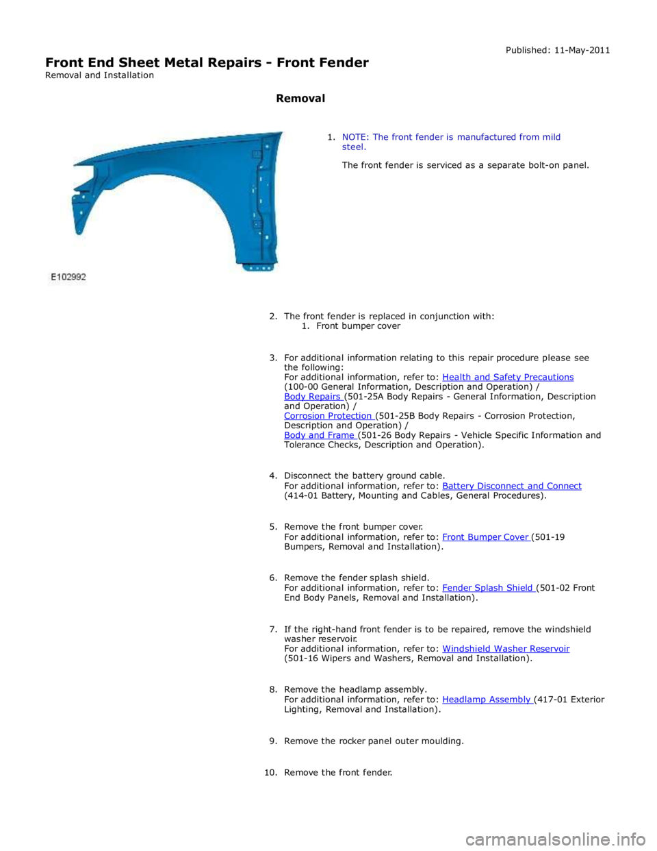
10. Remove the front fender.