Page 1605 of 3039
Published: 11-May-2011
Fuel Tank and Lines - V8 5.0L Petrol/V8 S/C 5.0L Petrol - Fuel Tank
Removal and Installation
Removal
NOTE: Removal steps in this procedure may contain installation details.
1. Refer to: Petrol and Petrol-Ethanol Fuel Systems Health and Safety Precautions (100-00 General Information, Description and Operation).
2. Refer to: Battery Disconnect and Connect (414-01 Battery, Mounting and Cables, General Procedures).
3. Refer to: Fuel Tank Draining (310-00 Fuel System - General Information, General Procedures).
4. WARNING: Do not work on or under a vehicle supported only by a jack.
Always support the vehicle on safety stands.
Raise and support the vehicle.
5. Refer to: Driveshaft - V8 5.0L Petrol/V8 S/C 5.0L Petrol (205-01 Driveshaft, Removal and Installation).
6. NOTE: Some variation in the illustrations may occur, but
the essential information is always correct.
Torque: 10 Nm
7. Torque: 4.8 Nm
Page 1609 of 3039
Published: 18-Jun-2014
Fuel Tank and Lines - V8 5.0L Petrol/V8 S/C 5.0L Petrol - Fuel Tank Filler
Pipe
Removal and Installation
Removal
NOTE: Removal steps in this procedure may contain installation details.
1. Refer to: Diesel Fuel System Health and Safety Precautions (100-00 General Information, Description and Operation).
Refer to: Petrol and Petrol-Ethanol Fuel Systems Health and Safety Precautions (100-00 General Information, Description and Operation).
2. Open the fuel filler door and remove the cap.
3. WARNING: Do not work on or under a vehicle supported only by a
jack. Always support the vehicle on safety stands.
Raise and support the vehicle.
4. Refer to: Battery Disconnect and Connect (414-01 Battery, Mounting and Cables, General Procedures).
5. Remove the right-hand wheel and tire.
Refer to: Wheel and Tire (204-04 Wheels and Tires, Removal and Installation).
Page 1614 of 3039
Published: 31-Oct-2013
Fuel Tank and Lines - V8 5.0L Petrol/V8 S/C 5.0L Petrol - Fuel Rail High-Pressure Fuel Pump Supply Line
Removal and Installation
Removal
NOTES:
Some variation in the illustrations may occur, but the essential information is always correct.
Some illustrations may show the engine removed for clarity.
1. Depressurize the fuel system.
Refer to: Fuel System Pressure Release - V8 5.0L Petrol/V8 S/C 5.0L Petrol (310-00 Fuel System - General Information, General Procedures).
2. Refer to: Battery Disconnect and Connect (414-01 Battery, Mounting and Cables, General Procedures).
3. WARNING: Do not smoke or carry lighted tobacco or open
flame of any type when working on or near any fuel related
components. Highly flammable mixtures are always
present and may ignite. Failure to follow these instructions
may result in personal injury.
CAUTIONS:
Be prepared to collect escaping fuel.
Make sure that all openings are sealed. Use new
blanking caps.
Page 2216 of 3039
Body Closures - Fuel Filler Door Assembly
Removal and Installation
Removal
CAUTION: Do not align the bowl using the hinge arm.
NOTE: Removal steps in this procedure may contain installation details. Published: 11-May-2011
1. WARNING: Do not work on or under a vehicle supported only by a jack.
Always support the vehicle on safety stands.
Raise and support the vehicle.
2. Refer to: Fuel Tank Filler Pipe (310-01, Removal and Installation).
3.
4.
Page 2798 of 3039

Actuation, Removal and Installation).
12. Remove the left-hand and right-hand front seats.
For additional information, refer to: Front Seat (501-10 Seating, Removal and Installation).
13. Remove the heater core and evaporator core housing.
For additional information, refer to: Heater Core and Evaporator Core Housing (412-01 Climate Control, Removal and Installation).
14. Remove the front safety belt retractor.
For additional information, refer to: Front Safety Belt Retractor (501-20A Safety Belt System, Removal and Installation).
15. Remove the B-pillar side impact sensor.
For additional information, refer to: B-Pillar Side Impact Sensor (501-20B Supplemental Restraint System, Removal and Installation).
16. Remove the left-hand and right-hand front floor covering.
17. Remove the rear floor covering.
18. If the left-hand front side member and suspension top mount assembly
is to be repaired, remove the left-hand rear foot well duct.
19. If the right-hand front side member and suspension top mount assembly
is to be repaired, remove the right-hand rear foot well duct.
20. If the drivers side front side member and suspension top mount is being
repaired, remove the pedal box.
21. Release and position the insulating material at the inner bulkhead to
one side.
22. Release and position the inner bulkhead and floor panel wiring harness
to one side.
23. Drain the fuel tank.
For additional information, refer to: Fuel Tank Draining (310-00 Fuel System - General Information, General Procedures).
24. If the left-hand front side member and suspension top mount assembly
is to be repaired, remove the left-hand under shield.
25. If the right-hand front side member and suspension top mount assembly
is to be repaired, remove the right-hand under shield.
26. If the left-hand front side member and suspension top mount assembly
is to be repaired, remove the fuel supply and return pipes.
27. For diesel engine vehicles only, if the left-hand front side member and
suspension top mount assembly is to be repaired, remove the fuel
cooler.
28. If the right-hand front side member and suspension top mount assembly
is to be repaired, release and position the underfloor wiring harness to
Page 2950 of 3039

Supplemental Restraint System, Removal and Installation).
23. Remove the rear window glass.
24. Remove the audio unit antenna amplifier.
For additional information, refer to: Audio Unit Antenna Amplifier (415-01A Information and Entertainment System, Removal and
Installation).
25. If the left-hand rear quarter panel is to be repaired, remove the diversity
antenna module.
26. Remove the C-Pillar side impact sensor.
For additional information, refer to: C-Pillar Side Impact Sensor (501-20B Supplemental Restraint System, Removal and Installation).
27. Remove the rear door striker.
28. Remove the luggage compartment lid.
29. If the right-hand rear quarter panel is to be repaired, drain the fuel tank.
For additional information, refer to: Fuel Tank Draining (310-00 Fuel System - General Information, General Procedures).
30. If the right-hand rear quarter panel is to be repaired, remove the fuel
filler door.
31. If the right-hand rear quarter panel is to be repaired, remove the fuel
tank filler pipe.
For additional information, refer to: Fuel Tank Filler Pipe (310-01 Fuel
Tank and Lines - 3.0L, Removal and Installation) /
Fuel Tank Filler Pipe (310-01 Fuel Tank and Lines - 4.2L, Removal and
Installation).
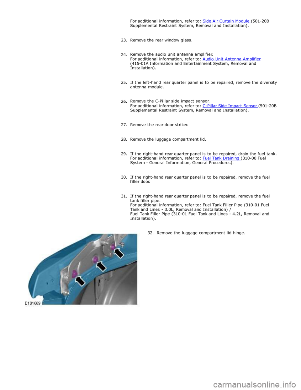
32. Remove the luggage compartment lid hinge.
Page 2993 of 3039
5. Disconnect the generator electrical connectors.
6. Disconnect the battery positive cable and position it to one side.
7. Remove the rear subframe and rear suspension, as an assembly.
For additional information, refer to: Rear Subframe - V6 3.0L Petrol (502-00 Uni-Body, Subframe and Mounting System, Removal and
Installation).
8. Remove the fuel tank filler pipe.
For additional information, refer to: Fuel Tank Filler Pipe (310-01B,
Removal and Installation).
9. Release the left-hand and right-hand luggage floor wiring harnesses and
position them to one side.
10. Make sure that the rear seats are covered to prevent any damage during
this repair procedure.
11. NOTE: If undamaged, the left-hand and right-hand rear bumper
retaining brackets should be reinstalled.
Remove the left-hand and right-hand rear bumper retaining brackets.
Page 3032 of 3039

Published: 11-May-2011
Uni-Body, Subframe and Mounting System - Rear Subframe V8 5.0L Petrol/V8 S/C 5.0L Petrol
Removal and Installation
General Equipment
Removal
NOTE: Removal steps in this procedure may contain installation details.
1. Refer to: Petrol and Petrol-Ethanol Fuel Systems Health and Safety Precautions (100-00 General Information, Description and Operation).
2. WARNING: Do not work on or under a vehicle supported only by a jack.
Always support the vehicle on safety stands.
Raise and support the vehicle.
3. Refer to: Fuel Tank Draining (310-00 Fuel System - General Information, General Procedures).
4. Refer to: Wheel and Tire (204-04 Wheels and Tires, Removal and Installation).
5. Refer to: Driveshaft - V8 5.0L Petrol/V8 S/C 5.0L Petrol (205-01 Driveshaft, Removal and Installation).
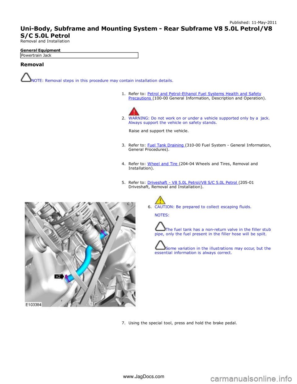
6. CAUTION: Be prepared to collect escaping fluids.
NOTES:
The fuel tank has a non-return valve in the filler stub
pipe, only the fuel present in the filler hose will be spilt.
Some variation in the illustrations may occur, but the
essential information is always correct.
7. Using the special tool, press and hold the brake pedal. Powertrain Jack www.JagDocs.com