2010 JAGUAR XFR TPMS
[x] Cancel search: TPMSPage 454 of 3039

Disconnect the Tire Pressure Monitoring System module connector, C3MC39A.
2 Measure the resistance between: C1MC40, harness side Battery Pin 2 Negative terminal Is the resistance less than 10,000 ohms?
Yes
REPAIR the short circuit. This circuit contains intermediate
connector, C13-B. For additional information, refer to the wiring
diagram. Clear the DTC and run an On Demand Self Test (ODST)
using the manufacturer approved diagnostic system to confirm
rectification.
No
INSTALL a new Tire Pressure Monitoring System module. REFER to:
Tire Pressure Monitoring System (TPMS) Module (204-04 Wheels and Tires, Removal and Installation). B6: CHECK WHETHER THE SHORT CIRCUIT IS IN THE HARNESS OR THE MODULE 1 Disconnect the Tire Pressure Monitoring System module connector, C3MC39A. 2 Measure the resistance between: C1MC40, harness side Battery Pin 2 Positive terminal Is the resistance less than 10,000 ohms?
Yes
REPAIR the short circuit. This circuit contains intermediate
connector, C13-B. For additional information, refer to the wiring
diagram. Clear the DTC and run an On Demand Self Test (ODST)
using the manufacturer approved diagnostic system to confirm
rectification.
No
INSTALL a new Tire Pressure Monitoring System module. REFER to:
Tire Pressure Monitoring System (TPMS) Module (204-04 Wheels and Tires, Removal and Installation). B7: CHECK WHETHER THE SHORT CIRCUIT IS IN THE HARNESS OR THE MODULE 1 Disconnect the Tire Pressure Monitoring System module connector, C3MC39A. www.JagDocs.com
Page 455 of 3039

2 Measure the resistance between: C1MC40, harness side Battery Pin 1 Negative terminal Is the resistance less than 10,000 ohms?
Yes
REPAIR the short circuit. This circuit contains intermediate
connector, C13-B. For additional information, refer to the wiring
diagram. Clear the DTC and run an On Demand Self Test (ODST)
using the manufacturer approved diagnostic system to confirm
rectification.
No
INSTALL a new Tire Pressure Monitoring System module. REFER to:
Tire Pressure Monitoring System (TPMS) Module (204-04 Wheels and Tires, Removal and Installation). B8: CHECK WHETHER THE SHORT CIRCUIT IS IN THE HARNESS OR THE MODULE 1 Disconnect the Tire Pressure Monitoring System module connector, C3MC39A. 2 Measure the resistance between: C1MC40, harness side Battery Pin 1 Positive terminal Is the resistance less than 10,000 ohms?
Yes
REPAIR the short circuit. This circuit contains intermediate
connector, C13-B. For additional information, refer to the wiring
diagram. Clear the DTC and run an On Demand Self Test (ODST)
using the manufacturer approved diagnostic system to confirm
rectification.
No
INSTALL a new Tire Pressure Monitoring System module. REFER to:
Tire Pressure Monitoring System (TPMS) Module (204-04 Wheels and Tires, Removal and Installation). B9: CHECK THE INITIATOR CIRCUIT FOR HIGH RESISTANCE 1 Measure the resistance between: C3MC39A, harness side C1MC40, harness side Pin 14 Pin 2
Page 456 of 3039

B10: CHECK THE INITIATOR CIRCUIT FOR HIGH RESISTANCE 1 Measure the resistance between: C3MC39A, harness side C1MC40, harness side Pin 13 Pin 1 Is the resistance greater than 5 ohms?
Yes
REPAIR the high resistance circuit. This circuit contains
intermediate connector, C13-B. For additional information, refer to
the wiring diagram. Clear the DTC and run an On Demand Self Test
(ODST) using the manufacturer approved diagnostic system to
confirm rectification.
No
INSTALL a new left hand front low-frequency initiator. REFER to:
Tire Pressure Monitoring System (TPMS) Front Antenna (204-04 Wheels and Tires, Removal and Installation).
PINPOINT TEST C : RIGHT FRONT LOW FREQUENCY INITIATOR CIRCUIT TEST CONDITIONS DETAILS/RESULTS/ACTIONS C1: CHECK THE INITIATOR CIRCUIT FOR SHORT CIRCUIT TO GROUND 1 Ignition off. 2 Disconnect the right hand front low-frequency initiator electrical connector, C1MC41.
3 Measure the resistance between: C1MC41, harness side Battery Pin 2 Negative terminal Is the resistance less than 10,000 ohms?
Yes
GO to C5. No
GO to C2. C2: CHECK THE INITIATOR CIRCUIT FOR SHORT CIRCUIT TO POWER 1 Measure the resistance between: C1MC41, harness side Battery Pin 2 Positive terminal Is the resistance less than 10,000 ohms?
Yes
GO to C6. No
GO to C3. C3: CHECK THE INITIATOR CIRCUIT FOR SHORT CIRCUIT TO GROUND 1 Measure the resistance between: C1MC41, harness side Battery Pin 1 Negative terminal
Page 457 of 3039
No
GO to C4. C4: CHECK THE INITIATOR CIRCUIT FOR SHORT CIRCUIT TO POWER 1 Measure the resistance between: C1MC41, harness side Battery Pin 1 Positive terminal Is the resistance less than 10,000 ohms?
Yes
GO to C8. No
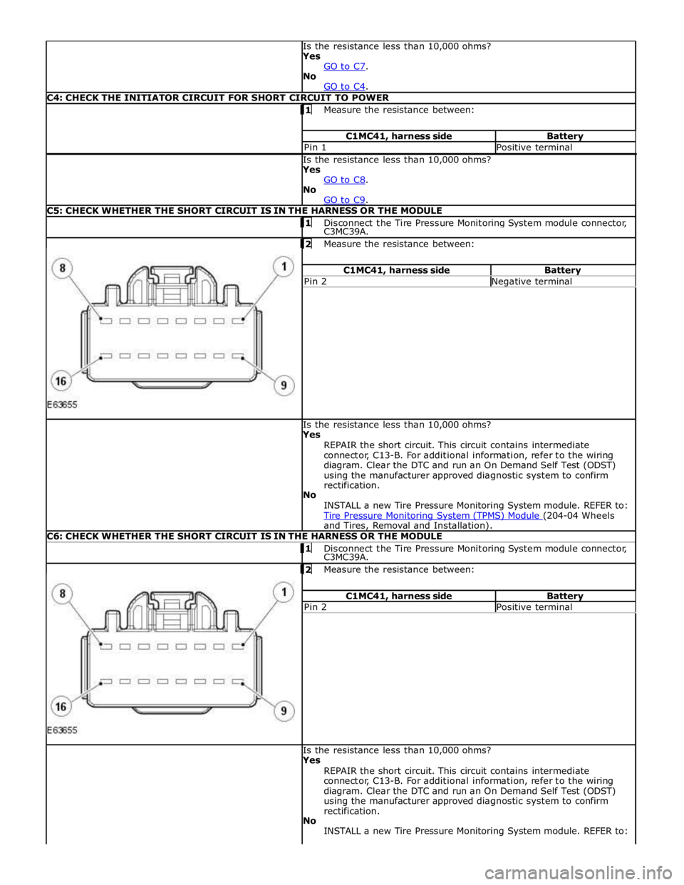
GO to C9. C5: CHECK WHETHER THE SHORT CIRCUIT IS IN THE HARNESS OR THE MODULE 1 Disconnect the Tire Pressure Monitoring System module connector, C3MC39A.
2 Measure the resistance between: C1MC41, harness side Battery Pin 2 Negative terminal Is the resistance less than 10,000 ohms?
Yes
REPAIR the short circuit. This circuit contains intermediate
connector, C13-B. For additional information, refer to the wiring
diagram. Clear the DTC and run an On Demand Self Test (ODST)
using the manufacturer approved diagnostic system to confirm
rectification.
No
INSTALL a new Tire Pressure Monitoring System module. REFER to:
Tire Pressure Monitoring System (TPMS) Module (204-04 Wheels and Tires, Removal and Installation). C6: CHECK WHETHER THE SHORT CIRCUIT IS IN THE HARNESS OR THE MODULE 1 Disconnect the Tire Pressure Monitoring System module connector, C3MC39A.
2 Measure the resistance between: C1MC41, harness side Battery Pin 2 Positive terminal Is the resistance less than 10,000 ohms?
Yes
REPAIR the short circuit. This circuit contains intermediate
connector, C13-B. For additional information, refer to the wiring
diagram. Clear the DTC and run an On Demand Self Test (ODST)
using the manufacturer approved diagnostic system to confirm
rectification.
No
INSTALL a new Tire Pressure Monitoring System module. REFER to:
Page 458 of 3039
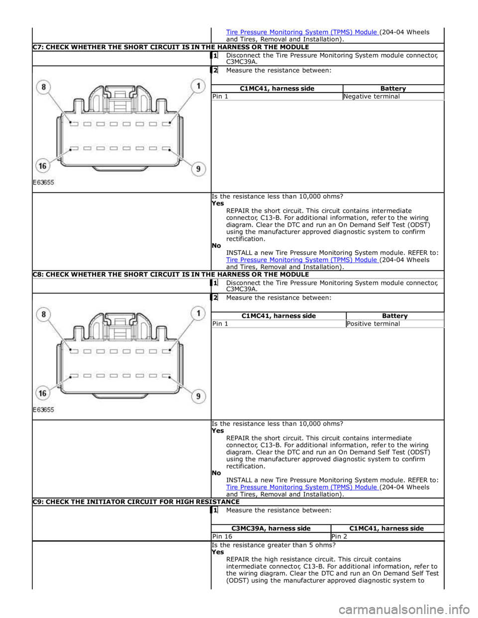
and Tires, Removal and Installation). C7: CHECK WHETHER THE SHORT CIRCUIT IS IN THE HARNESS OR THE MODULE 1 Disconnect the Tire Pressure Monitoring System module connector, C3MC39A.
2 Measure the resistance between: C1MC41, harness side Battery Pin 1 Negative terminal Is the resistance less than 10,000 ohms?
Yes
REPAIR the short circuit. This circuit contains intermediate
connector, C13-B. For additional information, refer to the wiring
diagram. Clear the DTC and run an On Demand Self Test (ODST)
using the manufacturer approved diagnostic system to confirm
rectification.
No
INSTALL a new Tire Pressure Monitoring System module. REFER to:
Tire Pressure Monitoring System (TPMS) Module (204-04 Wheels and Tires, Removal and Installation). C8: CHECK WHETHER THE SHORT CIRCUIT IS IN THE HARNESS OR THE MODULE 1 Disconnect the Tire Pressure Monitoring System module connector, C3MC39A.
2 Measure the resistance between: C1MC41, harness side Battery Pin 1 Positive terminal Is the resistance less than 10,000 ohms?
Yes
REPAIR the short circuit. This circuit contains intermediate
connector, C13-B. For additional information, refer to the wiring
diagram. Clear the DTC and run an On Demand Self Test (ODST)
using the manufacturer approved diagnostic system to confirm
rectification.
No
INSTALL a new Tire Pressure Monitoring System module. REFER to:
Tire Pressure Monitoring System (TPMS) Module (204-04 Wheels and Tires, Removal and Installation). C9: CHECK THE INITIATOR CIRCUIT FOR HIGH RESISTANCE 1 Measure the resistance between: C3MC39A, harness side C1MC41, harness side Pin 16 Pin 2 Is the resistance greater than 5 ohms?
Yes
REPAIR the high resistance circuit. This circuit contains
intermediate connector, C13-B. For additional information, refer to
the wiring diagram. Clear the DTC and run an On Demand Self Test
(ODST) using the manufacturer approved diagnostic system to
Page 459 of 3039
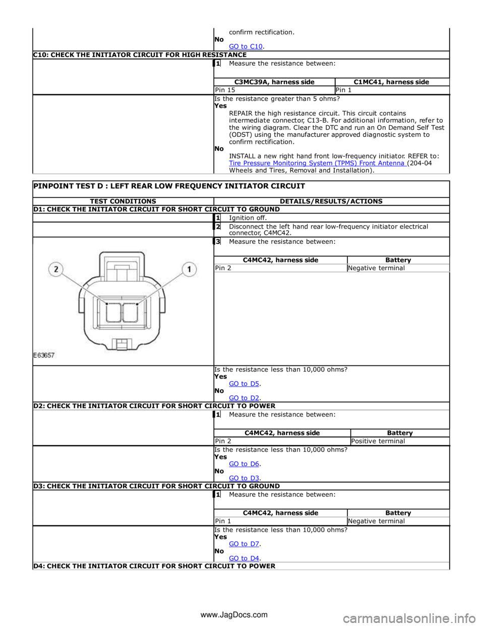
C10: CHECK THE INITIATOR CIRCUIT FOR HIGH RESISTANCE 1 Measure the resistance between: C3MC39A, harness side C1MC41, harness side Pin 15 Pin 1 Is the resistance greater than 5 ohms?
Yes
REPAIR the high resistance circuit. This circuit contains
intermediate connector, C13-B. For additional information, refer to
the wiring diagram. Clear the DTC and run an On Demand Self Test
(ODST) using the manufacturer approved diagnostic system to
confirm rectification.
No
INSTALL a new right hand front low-frequency initiator. REFER to:
Tire Pressure Monitoring System (TPMS) Front Antenna (204-04 Wheels and Tires, Removal and Installation).
PINPOINT TEST D : LEFT REAR LOW FREQUENCY INITIATOR CIRCUIT TEST CONDITIONS DETAILS/RESULTS/ACTIONS D1: CHECK THE INITIATOR CIRCUIT FOR SHORT CIRCUIT TO GROUND 1 Ignition off. 2 Disconnect the left hand rear low-frequency initiator electrical connector, C4MC42.
3 Measure the resistance between: C4MC42, harness side Battery Pin 2 Negative terminal Is the resistance less than 10,000 ohms?
Yes
GO to D5. No
GO to D2. D2: CHECK THE INITIATOR CIRCUIT FOR SHORT CIRCUIT TO POWER 1 Measure the resistance between: C4MC42, harness side Battery Pin 2 Positive terminal Is the resistance less than 10,000 ohms?
Yes
GO to D6. No
GO to D3. D3: CHECK THE INITIATOR CIRCUIT FOR SHORT CIRCUIT TO GROUND 1 Measure the resistance between: C4MC42, harness side Battery Pin 1 Negative terminal Is the resistance less than 10,000 ohms?
Yes
GO to D7. No
GO to D4. D4: CHECK THE INITIATOR CIRCUIT FOR SHORT CIRCUIT TO POWER www.JagDocs.com
Page 460 of 3039
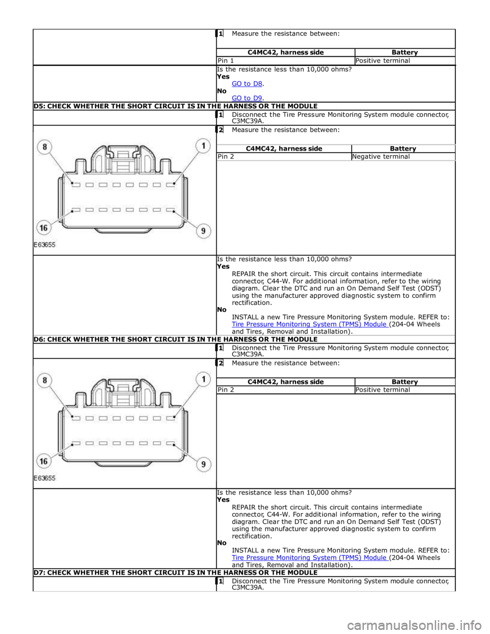
Measure the resistance between: C4MC42, harness side Battery Pin 1 Positive terminal Is the resistance less than 10,000 ohms?
Yes
GO to D8. No
GO to D9. D5: CHECK WHETHER THE SHORT CIRCUIT IS IN THE HARNESS OR THE MODULE 1 Disconnect the Tire Pressure Monitoring System module connector, C3MC39A.
2 Measure the resistance between: C4MC42, harness side Battery Pin 2 Negative terminal Is the resistance less than 10,000 ohms?
Yes
REPAIR the short circuit. This circuit contains intermediate
connector, C44-W. For additional information, refer to the wiring
diagram. Clear the DTC and run an On Demand Self Test (ODST)
using the manufacturer approved diagnostic system to confirm
rectification.
No
INSTALL a new Tire Pressure Monitoring System module. REFER to:
Tire Pressure Monitoring System (TPMS) Module (204-04 Wheels and Tires, Removal and Installation). D6: CHECK WHETHER THE SHORT CIRCUIT IS IN THE HARNESS OR THE MODULE 1 Disconnect the Tire Pressure Monitoring System module connector, C3MC39A. 2 Measure the resistance between: C4MC42, harness side Battery Pin 2 Positive terminal Is the resistance less than 10,000 ohms?
Yes
REPAIR the short circuit. This circuit contains intermediate
connector, C44-W. For additional information, refer to the wiring
diagram. Clear the DTC and run an On Demand Self Test (ODST)
using the manufacturer approved diagnostic system to confirm
rectification.
No
INSTALL a new Tire Pressure Monitoring System module. REFER to:
Tire Pressure Monitoring System (TPMS) Module (204-04 Wheels and Tires, Removal and Installation). D7: CHECK WHETHER THE SHORT CIRCUIT IS IN THE HARNESS OR THE MODULE 1 Disconnect the Tire Pressure Monitoring System module connector, C3MC39A.
Page 461 of 3039
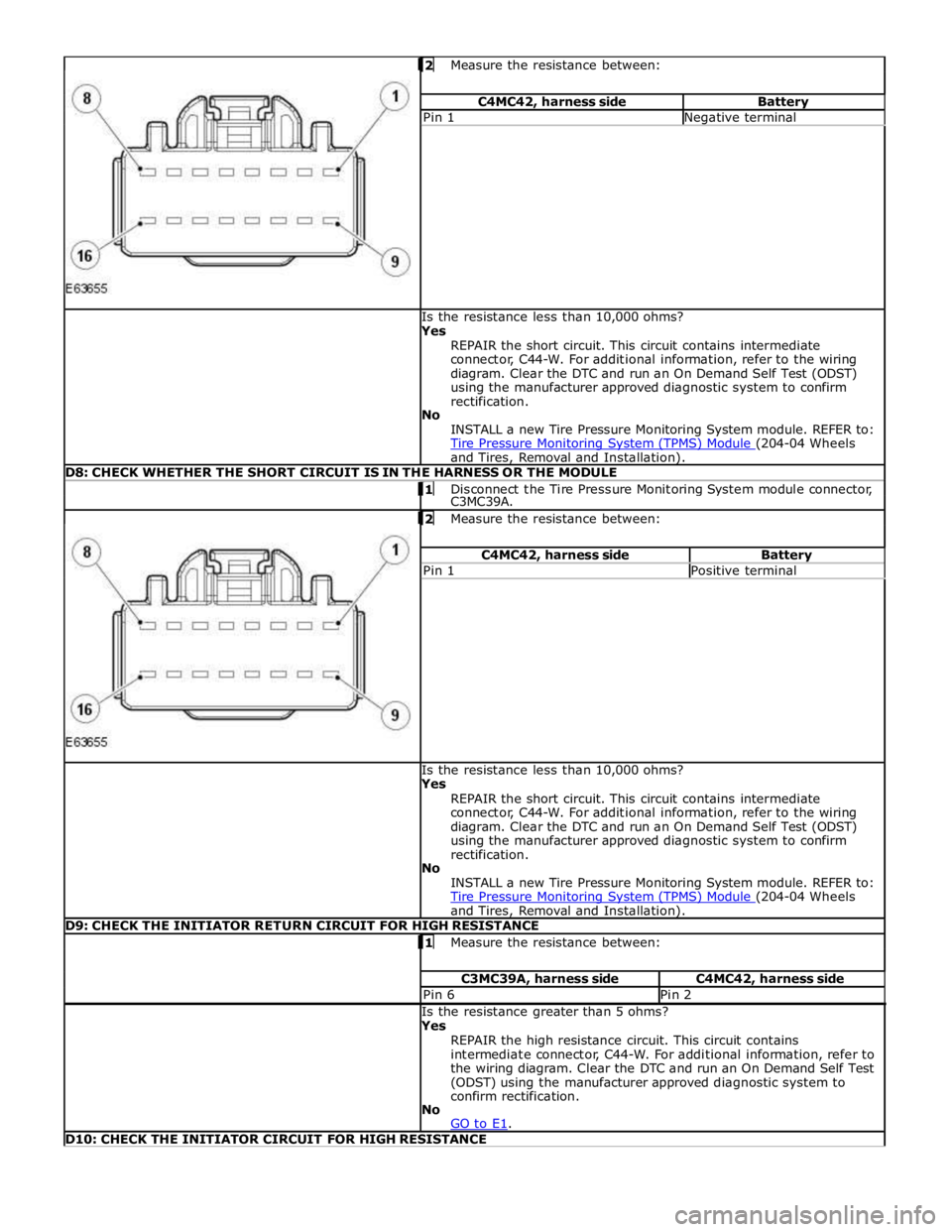
Measure the resistance between: C4MC42, harness side Battery Pin 1 Negative terminal Is the resistance less than 10,000 ohms?
Yes
REPAIR the short circuit. This circuit contains intermediate
connector, C44-W. For additional information, refer to the wiring
diagram. Clear the DTC and run an On Demand Self Test (ODST)
using the manufacturer approved diagnostic system to confirm
rectification.
No
INSTALL a new Tire Pressure Monitoring System module. REFER to:
Tire Pressure Monitoring System (TPMS) Module (204-04 Wheels and Tires, Removal and Installation). D8: CHECK WHETHER THE SHORT CIRCUIT IS IN THE HARNESS OR THE MODULE 1 Disconnect the Tire Pressure Monitoring System module connector, C3MC39A.
2 Measure the resistance between: C4MC42, harness side Battery Pin 1 Positive terminal Is the resistance less than 10,000 ohms?
Yes
REPAIR the short circuit. This circuit contains intermediate
connector, C44-W. For additional information, refer to the wiring
diagram. Clear the DTC and run an On Demand Self Test (ODST)
using the manufacturer approved diagnostic system to confirm
rectification.
No
INSTALL a new Tire Pressure Monitoring System module. REFER to:
Tire Pressure Monitoring System (TPMS) Module (204-04 Wheels and Tires, Removal and Installation). D9: CHECK THE INITIATOR RETURN CIRCUIT FOR HIGH RESISTANCE 1 Measure the resistance between: C3MC39A, harness side C4MC42, harness side Pin 6 Pin 2 Is the resistance greater than 5 ohms?
Yes
REPAIR the high resistance circuit. This circuit contains
intermediate connector, C44-W. For additional information, refer to
the wiring diagram. Clear the DTC and run an On Demand Self Test
(ODST) using the manufacturer approved diagnostic system to
confirm rectification.
No
GO to E1. D10: CHECK THE INITIATOR CIRCUIT FOR HIGH RESISTANCE