Page 867 of 3039
1 Oil pump outlet tube 2 Anti-drain valve 3 Oil cooler 4 Oil filter 5 Piston cooling jets 6 Timing chain lubrication jets 7 Oil evacuation tube 8 Oil pump 9 Oil temperature and level sensor 10 Oil pick-up The oil pump is attached to the underside of the windage tray. The input shaft of the oil pump is driven from the front of the
crankshaft, by the auxiliary chain, at 0.87 engine speed.
The oil pump draws oil from the sump pan through a centrally mounted pick-up pipe. The oil is pressurized and pumped
through an output tube to the cylinder block. After passing through an anti-drain valve and a plate type oil cooler, the oil is
filtered by a replaceable cartridge installed on the front of the RH cylinder head. LUBRICATION SYSTEM
Page 868 of 3039

cooling jets and the timing chain lubrication jets.
The oil returns to the oil pan under gravity. Large drain holes through the cylinder heads and cylinder block ensure the rapid
return of the oil to the sump pan. System replenishment is through the oil filler cap on the LH cylinder head cover.
An oil evacuation tube is installed to allow oil to be drawn from the sump pan. The upper end of the oil evacuation tube is
located under the oil filler cap.
An oil drain plug is installed in the RH side of the sump pan.
Oil Pump Nominal Operating Pressures
Engine Speed, rev/min Temperature, °C (°F) Pressure, bar (lbf/in2
) Idle 20 (68) 2.0 (29.0) 1500 20 (68) 6.0 (87.0) 3000 40 (104) 6.2 (90.0) 3000 110 (230) 5.0 (72.5) 3000 130 (266) 4.0 (58.0) Oil Level Monitoring
Oil level monitoring is provided by an oil level and temperature sensor that measures the oil level in the sump pan. The oil
level can be displayed in the message center of the instrument cluster.
The oil level and temperature sensor supplies the ECM with a signal containing the level and temperature of the oil in the sump pan. The oil level and temperature sensor is secured to the bottom of the sump pan with three screws and sealed with a
gasket.
The oil level and temperature sensor sends an ultrasonic pulse vertically upward and measures the time taken for the pulse to
be reflected back from the top surface of the oil. This time is compared with the time taken for an ultrasonic pulse to travel a
reference distance within the oil level and temperature sensor to determine the oil level. The oil level reading is combined with
the oil temperature reading and transmitted in a PWM signal to the ECM.
Oil Level and Temperature Sensor Specifications
Feature Details Power source Battery Voltage Level Accuracy ±2 mm (±0.08 in.) at temperatures of -30 °C (-22 °F)) and above; (±4 mm (±0.16 in.) at
temperatures below -30 °C (-22 °F)) Temperature Accuracy ±2 °C (±3.6 °F) Operating Level Range 116 to 147 mm (4.57 to 5.79 in.)
Page 911 of 3039
Removal
NOTE: Removal steps in this procedure may contain installation details.
1. Refer to: Battery Disconnect and Connect (414-01 Battery, Mounting and Cables, General Procedures).
2. WARNING: Make sure to support the vehicle with axle stands.
Raise and support the vehicle.
3. Refer to: Cooling Fan Motor and Shroud - Vehicles With: Supercharger (303-03C Engine Cooling - V8 5.0L Petrol/V8 S/C 5.0L Petrol, Removal
and Installation).
4. Refer to: Starter Motor (303-06C Starting System - V8 5.0L Petrol/V8 S/C 5.0L Petrol, Removal and Installation).
5. www.JagDocs.com
Page 929 of 3039
5.0L Petrol, Removal and Installation).
23. Refer to: Cooling Fan Motor and Shroud - Vehicles With: Supercharger (303-03C Engine Cooling - V8 5.0L Petrol/V8 S/C 5.0L Petrol, Removal
and Installation).
24. Refer to: Battery Disconnect and Connect (414-01 Battery, Mounting and Cables, General Procedures).
Page 986 of 3039
Engine - V8 S/C 5.0L Petrol - Oil Cooler
Removal and Installation
Removal
NOTE: Removal steps in this procedure may contain installation details. Published: 19-Nov-2013
1. Refer to: Battery Disconnect and Connect (414-01 Battery, Mounting and Cables, General Procedures).
2. WARNING: Make sure to support the vehicle with axle stands.
Raise and support the vehicle.
3. Refer to: Cooling System Partial Draining, Filling and Bleeding - V8 S/C 5.0L Petrol (303-03C Engine Cooling - V8 5.0L Petrol/V8 S/C 5.0L Petrol, General Procedures).
4. Refer to: Supercharger (303-12D Intake Air Distribution and Filtering - V8 S/C 5.0L Petrol, Removal and Installation).
5.
6. www.JagDocs.com
Page 1025 of 3039

Engine - V8 S/C 5.0L Petrol - Timing Cover
Removal and Installation
Removal
NOTE: Removal steps in this procedure may contain installation details. Published: 12-Sep-2011
1. Refer to: Battery Disconnect and Connect (414-01 Battery, Mounting and Cables, General Procedures).
2. WARNING: Make sure to support the vehicle with axle stands.
Raise and support the vehicle.
3. Refer to: Accessory Drive Belt (303-05D Accessory Drive - V8 S/C 5.0L Petrol, Removal and Installation).
4. Refer to: Accessory Drive Belt Tensioner (303-05D Accessory Drive - V8 S/C 5.0L Petrol, Removal and Installation).
5. Refer to: Thermostat Housing - Vehicles With: Supercharger (303-03C Engine Cooling - V8 5.0L Petrol/V8 S/C 5.0L Petrol, Removal and
Installation).
6. Refer to: Valve Cover LH (303-01D Engine - V8 S/C 5.0L Petrol, Removal and Installation).
7. Refer to: Valve Cover RH (303-01D Engine - V8 S/C 5.0L Petrol, Removal and Installation).
8. Refer to: Crankshaft Pulley (303-01D Engine - V8 S/C 5.0L Petrol, Removal and Installation).
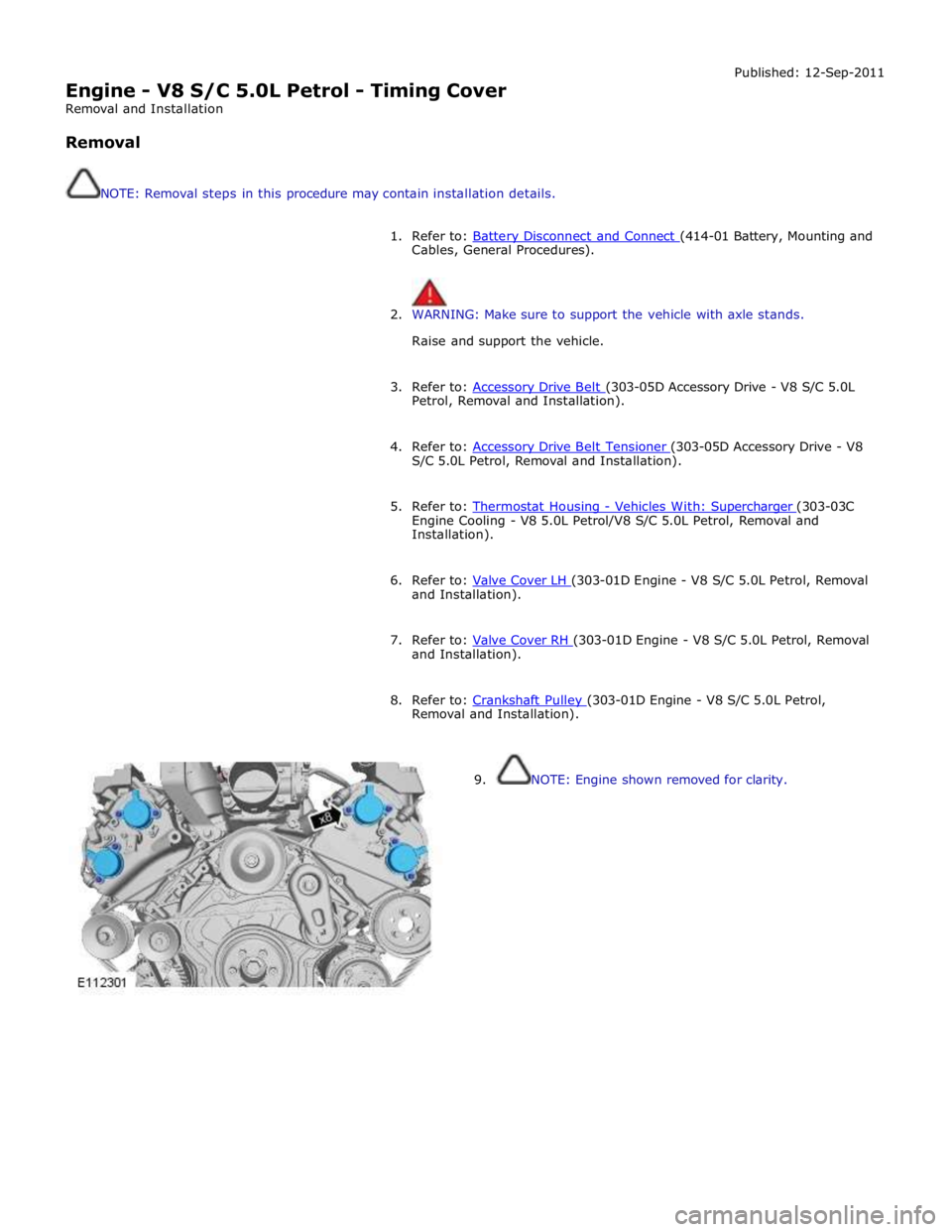
9. NOTE: Engine shown removed for clarity.
Page 1031 of 3039
12.
Refer to: Crankshaft Pulley (303-01D Engine - V8 S/C 5.0L Petrol, Removal and Installation).
13. Refer to: Valve Cover RH (303-01D Engine - V8 S/C 5.0L Petrol, Removal and Installation).
14. Refer to: Valve Cover LH (303-01D Engine - V8 S/C 5.0L Petrol, Removal and Installation).
15. Refer to: Thermostat Housing - Vehicles With: Supercharger (303-03C Engine Cooling - V8 5.0L Petrol/V8 S/C 5.0L Petrol, Removal and
Installation).
16. Refer to: Accessory Drive Belt Tensioner (303-05D Accessory Drive - V8 S/C 5.0L Petrol, Removal and Installation).
17. Refer to: Accessory Drive Belt (303-05D Accessory Drive - V8 S/C 5.0L Petrol, Removal and Installation).
18. Refer to: Battery Disconnect and Connect (414-01 Battery, Mounting and Cables, General Procedures). www.JagDocs.com
Page 1087 of 3039

Engine - V8 S/C 5.0L Petrol - Engine
Removal Published: 19-Nov-2013
NOTES:
Some variation in the illustrations may occur, but the essential information is always correct.
If a new engine is to be installed, remove the intake manifold to access the top transmission retaining bolts.
1. Refer to: Battery Disconnect and Connect (414-01 Battery, Mounting and Cables, General Procedures).
2. WARNING: Make sure to support the vehicle with axle stands.
Raise and support the vehicle.
3. Refer to: Cowl Vent Screen (501-02 Front End Body Panels, Removal and Installation).
4. Refer to: Air Cleaner LH (303-12C Intake Air Distribution and Filtering - V8 5.0L Petrol, Removal and Installation).
5. Refer to: Air Cleaner RH (303-12C Intake Air Distribution and Filtering - V8 5.0L Petrol, Removal and Installation).
6. Refer to: Cooling System Partial Draining, Filling and Bleeding - V8 S/C 5.0L Petrol (303-03C Engine Cooling - V8 5.0L Petrol/V8 S/C 5.0L Petrol, General Procedures).
7. Refer to: Air Conditioning (A/C) System Recovery, Evacuation and Charging (412-00 Climate Control System - General Information, General Procedures).
8. Refer to: Hood (501-02 Front End Body Panels, Removal and Installation).
9. Refer to: Cooling Fan Motor and Shroud - Vehicles With: Supercharger (303-03C Engine Cooling - V8 5.0L Petrol/V8 S/C 5.0L Petrol, Removal
and Installation).
10. Refer to: Transmission - V8 5.0L Petrol/V8 S/C 5.0L Petrol (307-01B Automatic Transmission/Transaxle - TDV6 3.0L Diesel /V8 5.0L Petrol/V8
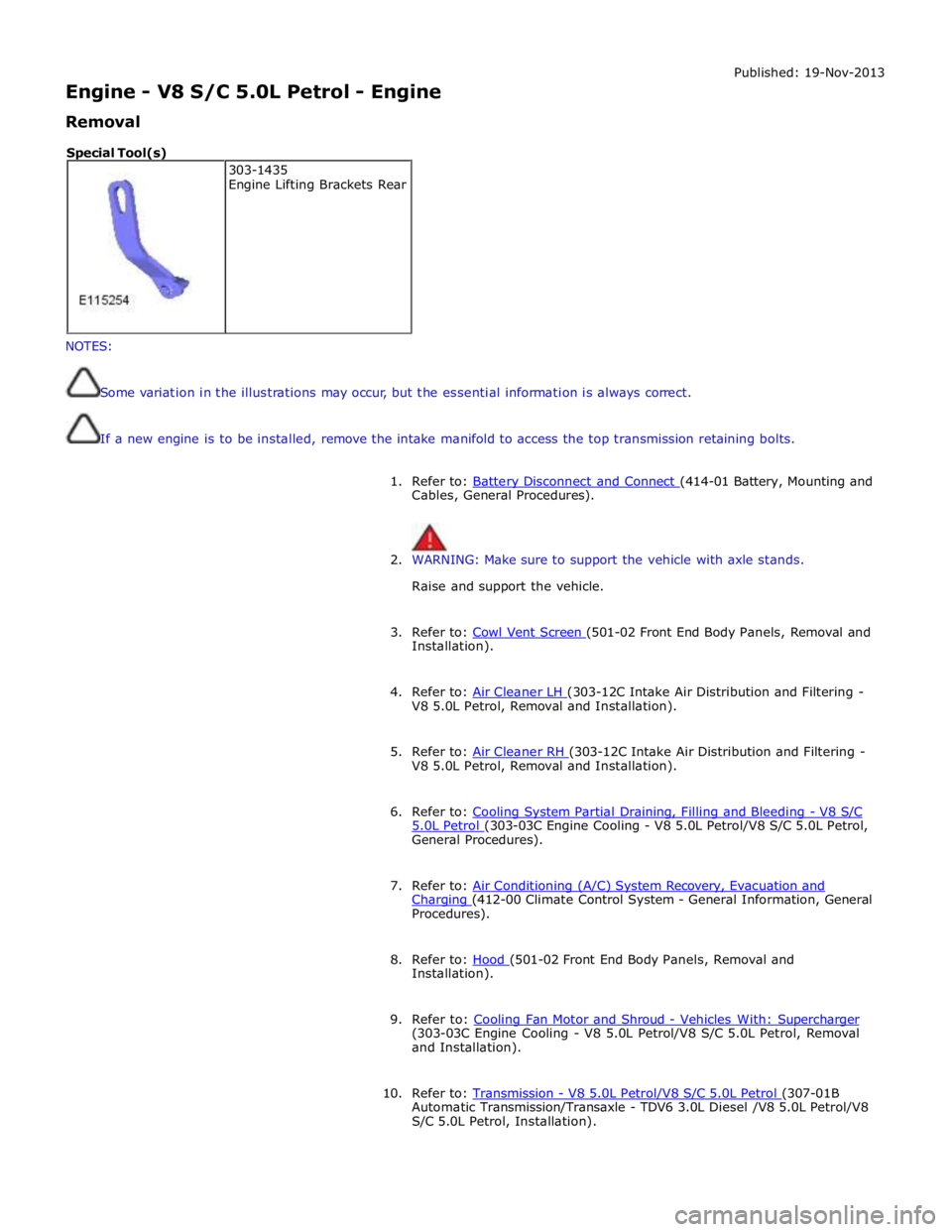
S/C 5.0L Petrol, Installation). 303-1435
Engine Lifting Brackets Rear Special Tool(s)