2010 JAGUAR XFR power steering
[x] Cancel search: power steeringPage 1247 of 3039
Published: 11-May-2011
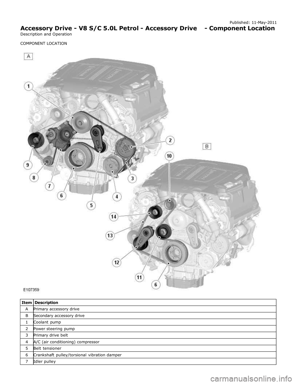
Accessory Drive - V8 S/C 5.0L Petrol - Accessory Drive - Component Location
Description and Operation
COMPONENT LOCATION
Item Description A Primary accessory drive B Secondary accessory drive 1 Coolant pump 2 Power steering pump 3 Primary drive belt 4 A/C (air conditioning) compressor 5 Belt tensioner 6 Crankshaft pulley/torsional vibration damper 7 Idler pulley
Page 1249 of 3039
Published: 11-May-2011
Accessory Drive - V8 S/C 5.0L Petrol - Accessory Drive - Overview
Description and Operation
OVERVIEW
The accessory drive is a belt system powered by a pulley attached to the front of the crankshaft. The crankshaft pulley, which
incorporates a torsional vibration damper, drives two drive belts. An automatic belt tensioner in each belt run maintains the
drive belt at the correct tension. Together with idler pulleys, the belt tensioners also guide the drive belts clear of obstructions
and set the correct 'wrap-around' of the accessory component drive pulleys to ensure a slip-free drive.
PRIMARY DRIVE BELT
The primary drive belt is a six-ribbed poly-V belt that drives the:
Coolant pump
Power steering pump
A/C (air conditioning) compressor
Generator.
SECONDARY DRIVE BELT
The secondary drive belt is an eight-ribbed poly-V belt that drives the SC (supercharger).
BELT TENSIONERS
Each belt tensioner consists of an idler pulley on the end of a spring loaded pivot arm. The pivot arms can be turned manually
for removal and installation of the drive belts.
Each belt tensioners is calibrated to automatically maintain the correct tension in the related drive belt.
Page 1373 of 3039

DTC Description Possible Causes Action B10AC-81
Cruise Control Switch -
invalid serial data received
The Engine Control Module
(ECM) has received an invalid
command from the steering
wheel switch pack Clear the DTC and press all the steering wheel
switches, re-check for DTCs. Refer to the
electrical circuit diagrams and check the Cruise
control switch circuit for open circuit, short to
power, short to ground, disconnected. Check
and install a new Steering Wheel Module (SWM) as required. B10AC-82 Cruise Control Switch - alive / sequence counter incorrect / not updated
Cruise Buttons alive counter is
not incrementing. Which
suggests that the LIN bus is
faulty
Steering Wheel Module (SWM) is
not connected
Steering Wheel Module (SWM)
failure Refer to the electrical circuit diagrams and
check the Cruise control switch circuit for open
circuit, short to power, short to ground,
disconnected. Check and install a new Steering
Wheel Module (SWM) as required. B10AC-83
Cruise Control Switch - value
of signal protection
calculation incorrect
Cruise buttons checksum
incorrect, incorrect cruise
switches fitted to vehicle Check and install new cruise switches as
required. B10AC-96
Cruise Control Switch -
component internal failure
Cruise control switch circuit,
open circuit, short to power,
short to ground, disconnected
Cruise Control Switch failure
Steering Wheel Module (SWM)
failure Check for related DTCs in other Central
Junction Box (CJB)s. Refer to the electrical
circuit diagrams and check the Cruise control
switch circuit for open circuit, short to power,
short to ground, disconnected. Check and
install a new cruise control switch as required.
Check and install a new Steering Wheel
Module (SWM) as required. B10FF-68
Ignition Control - Event
information
Spark plug(s) fault
Wiring harness fault
Ignition coil(s) fault Refer to repair manual and check spark plug(s)
for condition and security. Replace any
defective components as required. Refer to
electrical wiring diagrams and check ignition
coil circuit for intermittent open circuit, short
to power, short to ground. Check and install a
new coil(s) as required. B11DB-01
Battery Monitoring Module -
General Electrical Failure
Charging system fault Battery
monitoring signal line
circuit fault
Vehicle battery fault Refer to electrical wiring diagrams and check
charging system for faults. Perform any repairs
required. Refer to the electrical wiring
diagrams and check the Battery Monitoring
System (BMS) module circuit for open circuit,
short to ground, short to power. Refer to the
battery care manual and check and install a
new battery. B11DB-87
Battery Monitoring Module -
missing message
Battery signal line circuit fault Refer to the electrical wiring diagrams and
check the Battery Monitoring System (BMS)
module circuit for open circuit, short to ground,
short to power. B1206-68
Crash Occurred - event
information
Engine control Module (ECM) has
detected the vehicle has crashed
- event information DTC only Refer to the electrical circuit diagrams and
check the Engine Control Module (ECM) to
Restraints Control Module (RCM) circuit for
short to ground, short to power, open circuit.
Repair circuit as required, clear DTC and retest
system to confirm repair. C0031-00
Left Front Wheel Speed
Sensor - No sub type
information
Invalid data received from
Anti-lock Braking System (ABS)
module - left front wheel speed
signal fault Check Anti-lock Braking System (ABS) module
for related DTCs and refer to relevant DTC
Index. C0034-00
Right Front Wheel Speed
Sensor - No sub type
information
Invalid data received from
Anti-lock Braking System (ABS)
module - right front wheel speed
signal fault Check Anti-lock Braking System (ABS) module
for related DTCs and refer to relevant DTC
Index. C0037-00
Left Rear Wheel Speed
Sensor - No sub type
information
Invalid data received from
Anti-lock Braking System (ABS)
module - left rear wheel speed
signal fault Check Anti-lock Braking System (ABS) module
for related DTCs and refer to relevant DTC
Index. C003A-00
Right Rear Wheel Speed
Sensor - No sub type
information
Invalid data received from
Anti-lock Braking System (ABS)
module - right rear wheel speed
signal fault Check Anti-lock Braking System (ABS) module
for related DTCs and refer to relevant DTC
Index.
Page 1412 of 3039
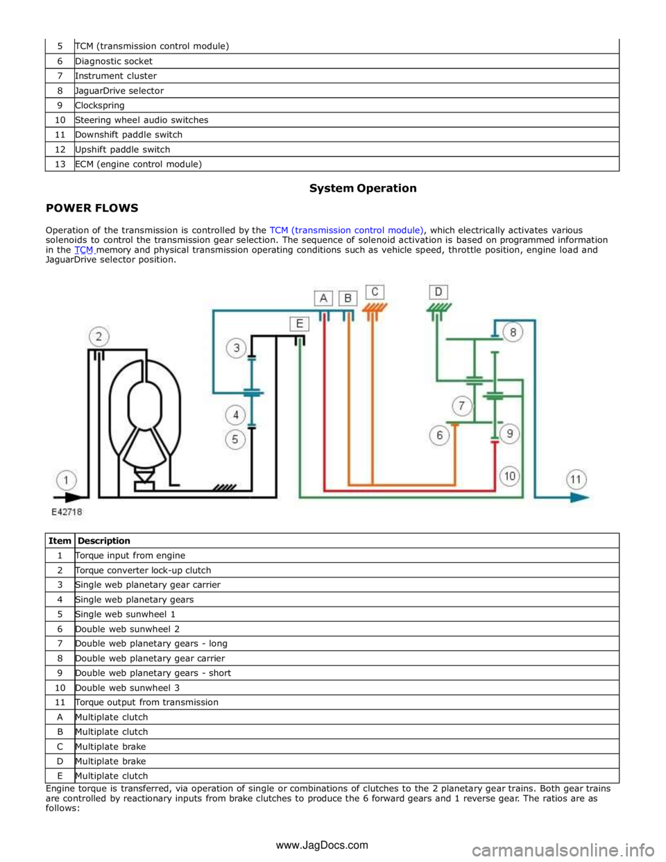
TCM (transmission control module) 6 Diagnostic socket 7 Instrument cluster 8 JaguarDrive selector 9 Clockspring 10 Steering wheel audio switches 11 Downshift paddle switch 12 Upshift paddle switch 13 ECM (engine control module)
POWER FLOWS System Operation
Operation of the transmission is controlled by the TCM (transmission control module), which electrically activates various
solenoids to control the transmission gear selection. The sequence of solenoid activation is based on programmed information
in the TCM memory and physical transmission operating conditions such as vehicle speed, throttle position, engine load and JaguarDrive selector position.
Item Description 1 Torque input from engine 2 Torque converter lock-up clutch 3 Single web planetary gear carrier 4 Single web planetary gears 5 Single web sunwheel 1 6 Double web sunwheel 2 7 Double web planetary gears - long 8 Double web planetary gear carrier 9 Double web planetary gears - short 10 Double web sunwheel 3 11 Torque output from transmission A Multiplate clutch B Multiplate clutch C Multiplate brake D Multiplate brake E Multiplate clutch Engine torque is transferred, via operation of single or combinations of clutches to the 2 planetary gear trains. Both gear trains
are controlled by reactionary inputs from brake clutches to produce the 6 forward gears and 1 reverse gear. The ratios are as
follows: www.JagDocs.com
Page 1422 of 3039
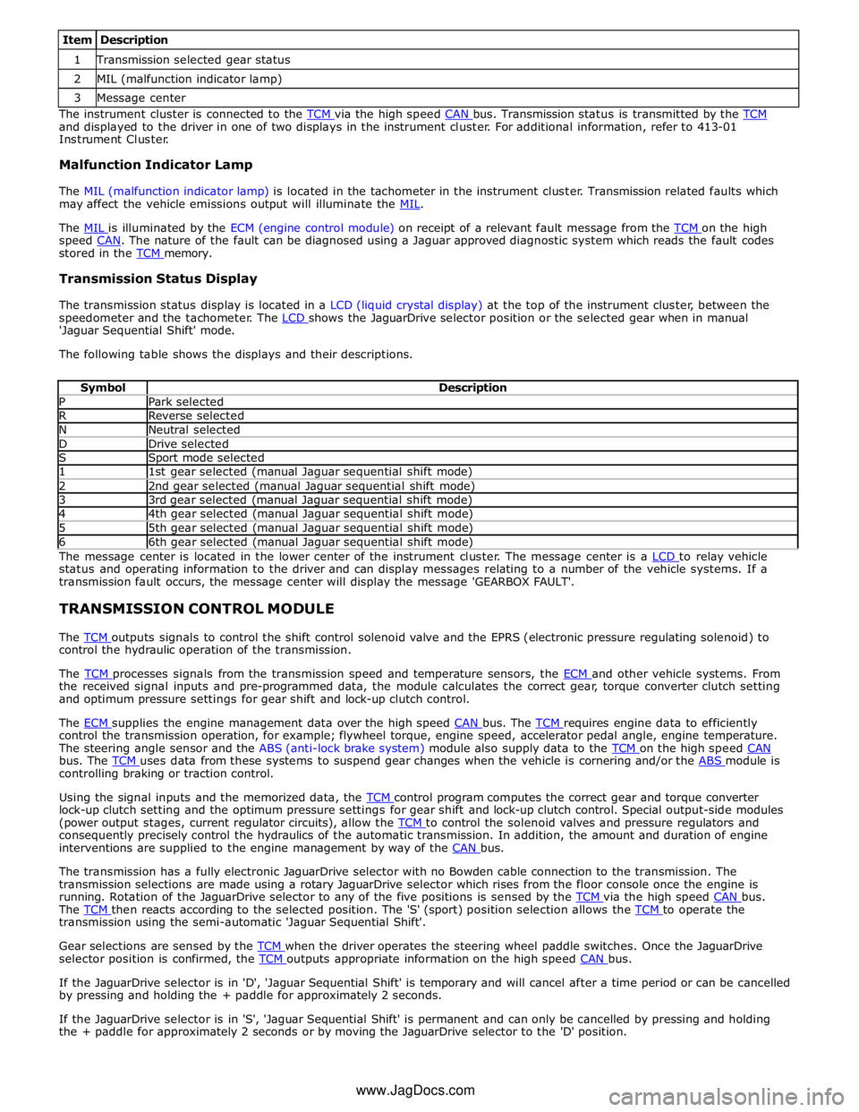
1 Transmission selected gear status 2 MIL (malfunction indicator lamp) 3 Message center The instrument cluster is connected to the TCM via the high speed CAN bus. Transmission status is transmitted by the TCM and displayed to the driver in one of two displays in the instrument cluster. For additional information, refer to 413-01
Instrument Cluster.
Malfunction Indicator Lamp
The MIL (malfunction indicator lamp) is located in the tachometer in the instrument cluster. Transmission related faults which
may affect the vehicle emissions output will illuminate the MIL.
The MIL is illuminated by the ECM (engine control module) on receipt of a relevant fault message from the TCM on the high speed CAN. The nature of the fault can be diagnosed using a Jaguar approved diagnostic system which reads the fault codes stored in the TCM memory.
Transmission Status Display
The transmission status display is located in a LCD (liquid crystal display) at the top of the instrument cluster, between the
speedometer and the tachometer. The LCD shows the JaguarDrive selector position or the selected gear when in manual 'Jaguar Sequential Shift' mode.
The following table shows the displays and their descriptions.
Symbol Description P Park selected R Reverse selected N Neutral selected D Drive selected S Sport mode selected 1 1st gear selected (manual Jaguar sequential shift mode) 2 2nd gear selected (manual Jaguar sequential shift mode) 3 3rd gear selected (manual Jaguar sequential shift mode) 4 4th gear selected (manual Jaguar sequential shift mode) 5 5th gear selected (manual Jaguar sequential shift mode) 6 6th gear selected (manual Jaguar sequential shift mode) The message center is located in the lower center of the instrument cluster. The message center is a LCD to relay vehicle status and operating information to the driver and can display messages relating to a number of the vehicle systems. If a
transmission fault occurs, the message center will display the message 'GEARBOX FAULT'.
TRANSMISSION CONTROL MODULE
The TCM outputs signals to control the shift control solenoid valve and the EPRS (electronic pressure regulating solenoid) to control the hydraulic operation of the transmission.
The TCM processes signals from the transmission speed and temperature sensors, the ECM and other vehicle systems. From the received signal inputs and pre-programmed data, the module calculates the correct gear, torque converter clutch setting
and optimum pressure settings for gear shift and lock-up clutch control.
The ECM supplies the engine management data over the high speed CAN bus. The TCM requires engine data to efficiently control the transmission operation, for example; flywheel torque, engine speed, accelerator pedal angle, engine temperature.
The steering angle sensor and the ABS (anti-lock brake system) module also supply data to the TCM on the high speed CAN bus. The TCM uses data from these systems to suspend gear changes when the vehicle is cornering and/or the ABS module is controlling braking or traction control.
Using the signal inputs and the memorized data, the TCM control program computes the correct gear and torque converter lock-up clutch setting and the optimum pressure settings for gear shift and lock-up clutch control. Special output-side modules
(power output stages, current regulator circuits), allow the TCM to control the solenoid valves and pressure regulators and consequently precisely control the hydraulics of the automatic transmission. In addition, the amount and duration of engine
interventions are supplied to the engine management by way of the CAN bus.
The transmission has a fully electronic JaguarDrive selector with no Bowden cable connection to the transmission. The
transmission selections are made using a rotary JaguarDrive selector which rises from the floor console once the engine is
running. Rotation of the JaguarDrive selector to any of the five positions is sensed by the TCM via the high speed CAN bus. The TCM then reacts according to the selected position. The 'S' (sport) position selection allows the TCM to operate the transmission using the semi-automatic 'Jaguar Sequential Shift'.
Gear selections are sensed by the TCM when the driver operates the steering wheel paddle switches. Once the JaguarDrive selector position is confirmed, the TCM outputs appropriate information on the high speed CAN bus.
If the JaguarDrive selector is in 'D', 'Jaguar Sequential Shift' is temporary and will cancel after a time period or can be cancelled
by pressing and holding the + paddle for approximately 2 seconds.
If the JaguarDrive selector is in 'S', 'Jaguar Sequential Shift' is permanent and can only be cancelled by pressing and holding
the + paddle for approximately 2 seconds or by moving the JaguarDrive selector to the 'D' position.
www.JagDocs.com
Page 1646 of 3039
Published: 08-Nov-2013
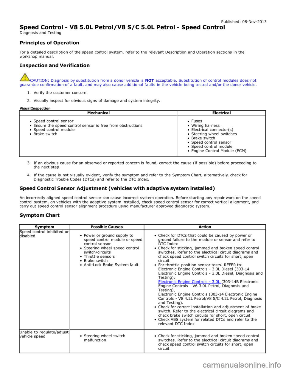
Speed Control - V8 5.0L Petrol/V8 S/C 5.0L Petrol - Speed Control
Diagnosis and Testing
Principles of Operation
For a detailed description of the speed control system, refer to the relevant Description and Operation sections in the
workshop manual.
Inspection and Verification
CAUTION: Diagnosis by substitution from a donor vehicle is NOT acceptable. Substitution of control modules does not
guarantee confirmation of a fault, and may also cause additional faults in the vehicle being tested and/or the donor vehicle.
1. Verify the customer concern.
2. Visually inspect for obvious signs of damage and system integrity.
Visual Inspection
Mechanical Electrical
Speed control sensor
Ensure the speed control sensor is free from obstructions
Speed control module
Brake switch
Fuses
Wiring harness
Electrical connector(s)
Steering wheel switches
Brake switch
Speed control sensor
Speed control module
Engine Control Module (ECM)
3. If an obvious cause for an observed or reported concern is found, correct the cause (if possible) before proceeding to
the next step.
4. If the cause is not visually evident, verify the symptom and refer to the Symptom Chart, alternatively, check for
Diagnostic Trouble Codes (DTCs) and refer to the DTC Index.
Speed Control Sensor Adjustment (vehicles with adaptive system installed)
An incorrectly aligned speed control sensor can cause incorrect system operation. Before starting any repair work on the speed
control system, on vehicles with the adaptive system installed, check speed control sensor for correct vertical alignment, and
carry out speed control sensor alignment procedure using manufacturer approved diagnostic system.
Symptom Chart
Symptom Possible Causes Action Speed control inhibited or
disabled
Power or ground supply to
speed control module or speed
control sensor
Steering wheel speed control
switch/circuits
Throttle sensors
Brake switch
Anti-Lock Brake System fault
Check for DTCs that could be caused by power or
ground failure to the module or sensor and refer to
DTC Index
Check for sticking, jammed and broken speed control
switches. Refer to the electrical circuit diagrams and
check speed control switch circuits for short, open
circuit
For throttle position sensor tests. REFER to:
Electronic Engine Controls - 3.0L Diesel (303-14
Electronic Engine Controls - 3.0L Diesel, Diagnosis and
Testing),
Electronic Engine Controls - 3.0L (303-14B Electronic Engine Controls - V6 3.0L Petrol, Diagnosis and
Testing),
Electronic Engine Controls (303-14 Electronic Engine
Controls - V8 4.2L Petrol/V8 S/C 4.2L Petrol, Diagnosis
and Testing).
Check for correct installation and adjustment of brake
switch. Refer to the electrical circuit diagrams and
check brake switch circuits for short, open circuit
Check ABS system for related DTCs and refer to the
relevant DTC Index Unable to regulate/adjust
vehicle speed
Steering wheel switch
malfunction
Check for sticking, jammed and broken speed control
switches. Refer to the electrical circuit diagrams and
check speed control switch circuits for short, open
circuit
Page 1773 of 3039

A/C compressor retaining bolts 25 18 - A/C compressor manifold and tube retaining bolt 9 - 80 A/C condenser core retaining studs 5 - 48 A/C condenser core supply and return lines retaining nuts 8 - 71 Power steering oil cooler retaining nuts 7 - 62 A/C desiccant bag retaining screw (vehicles fitted with petrol engines) 22 16 - A/C desiccant bag retaining screw (vehicles fitted with diesel engines) 4 - 37 A/C pressure cutoff switch 8 - 71
Page 1796 of 3039
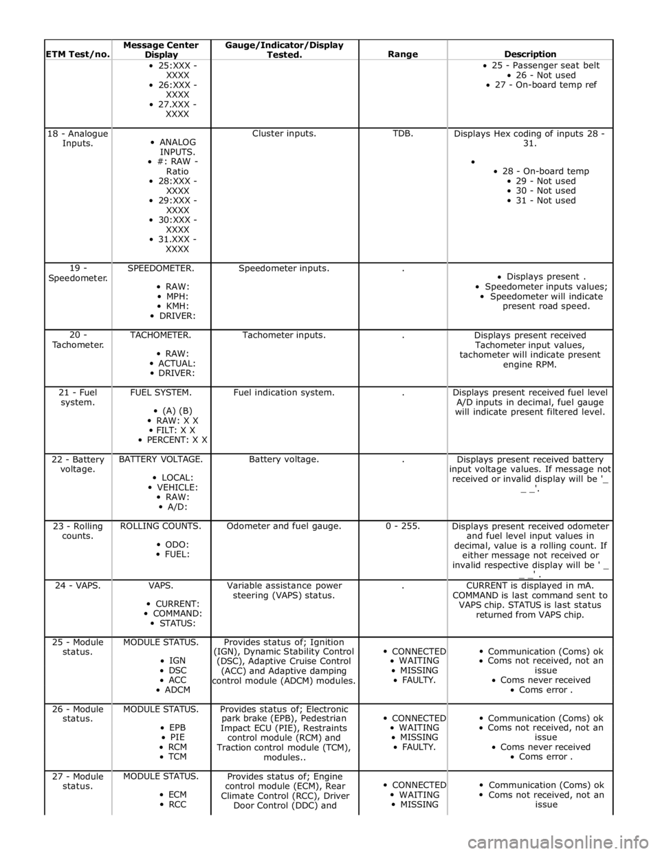
ETM Test/no. Message Center Display Gauge/Indicator/Display
Tested.
Range
Description 25:XXX -
XXXX
26:XXX -
XXXX
27.XXX -
XXXX 25 - Passenger seat belt
26 - Not used
27 - On-board temp ref 18 - Analogue
Inputs.
ANALOG
INPUTS.
#: RAW -
Ratio
28:XXX -
XXXX
29:XXX -
XXXX
30:XXX -
XXXX
31.XXX -
XXXX Cluster inputs. TDB.
Displays Hex coding of inputs 28 -
31.
28 - On-board temp
29 - Not used
30 - Not used
31 - Not used 19 -
Speedometer. SPEEDOMETER.
RAW:
MPH:
KMH:
DRIVER: Speedometer inputs. .
Displays present .
Speedometer inputs values;
Speedometer will indicate
present road speed. 20 -
Tachometer. TACHOMETER.
RAW:
ACTUAL:
DRIVER: Tachometer inputs. .
Displays present received
Tachometer input values,
tachometer will indicate present
engine RPM. 21 - Fuel
system. FUEL SYSTEM.
(A) (B)
RAW: X X
FILT: X X
PERCENT: X X Fuel indication system. .
Displays present received fuel level
A/D inputs in decimal, fuel gauge
will indicate present filtered level. 22 - Battery
voltage. BATTERY VOLTAGE.
LOCAL:
VEHICLE:
RAW:
A/D: Battery voltage. .
Displays present received battery
input voltage values. If message not
received or invalid display will be '_
_ _'. 23 - Rolling
counts. ROLLING COUNTS.
ODO:
FUEL: Odometer and fuel gauge. 0 - 255.
Displays present received odometer
and fuel level input values in
decimal, value is a rolling count. If
either message not received or
invalid respective display will be ' _
_ _' . 24 - VAPS. VAPS.
CURRENT:
COMMAND:
STATUS: Variable assistance power
steering (VAPS) status. .
CURRENT is displayed in mA.
COMMAND is last command sent to
VAPS chip. STATUS is last status
returned from VAPS chip. 25 - Module MODULE STATUS. Provides status of; Ignition
CONNECTED
Communication (Coms) ok status. (IGN), Dynamic Stability Control IGN
(DSC), Adaptive Cruise Control WAITING Coms not received, not an DSC
(ACC) and Adaptive damping MISSING issue ACC
control module (ADCM) modules. FAULTY. Coms never received ADCM Coms error . 26 - Module MODULE STATUS. Provides status of; Electronic
CONNECTED
Communication (Coms) ok status. park brake (EPB), Pedestrian EPB
Impact ECU (PIE), Restraints WAITING Coms not received, not an PIE
control module (RCM) and MISSING issue RCM
Traction control module (TCM), FAULTY. Coms never received TCM
modules.. Coms error . 27 - Module
status. MODULE STATUS.
ECM
RCC Provides status of; Engine
control module (ECM), Rear
Climate Control (RCC), Driver
Door Control (DDC) and
CONNECTED
WAITING
MISSING
Communication (Coms) ok
Coms not received, not an
issue