Page 471 of 4210

BR-26
< ON-VEHICLE REPAIR >
BRAKE BOOSTER
BRAKE BOOSTER
Removal and InstallationINFOID:0000000005147910
CAUTION:
• Be careful not to deform or bend brake piping while removing and installing brake booster.
• Replace clevis pin if it is damaged.
• Be careful not to damage brake booster stud bolt threads. If brake booster is tilted or inclined during
installation, dash panel may damage the threads.
• Attach the check valve in the correct direction.
REMOVAL
1. Remove engine room cover. Refer to EM-24, "Removal and Installation".
2. Remove engine air duct assembly. Refer to EM-25, "
Removal and Installation".
3. Remove cowl top extension. Refer to EXT-18, "
Removal and Installation".
4. Remove master cylinder assembly from brake booster. Refer to BR-25, "
Removal and Installation".
5. Remove vacuum hose from brake booster. Refer to BR-28, "
Removal and Installation".
6. Disconnect active boost and delta stroke s ensor harness connectors from brake booster.
7. Remove instrument lower panel LH. Refer to IP-14, "
Exploded View".
8. Remove brake pedal to clevis attachment snap pin and clevis pin from inside the vehicle.
9. Remove brake booster to brake pedal assembly nuts.
10. Reposition the A/C line out of the way.
11. Remove brake booster and spacer block from dash panel.
INSPECTION AFTER REMOVAL
Output Rod Length Inspection
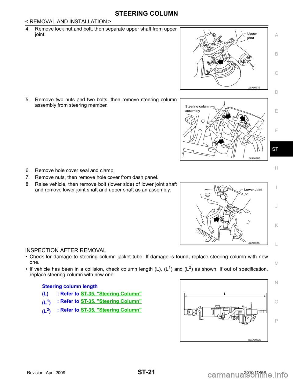
1. Reservoir tank 2. Master cylinder assembly 3. Gasket
4. Brake pedal 5. Lock nut 6. Spacer block
7. Brake booster 8. Active booster 9. Delta stroke sensor
AWFIA0416GB
Revision: April 20092010 QX56
Page 472 of 4210

BRAKE BOOSTERBR-27
< ON-VEHICLE REPAIR >
C
DE
G H
I
J
K L
M A
B
BR
N
O P
1. Using a hand vacuum pump, apply a vacuum of – 66.7 kPa (– 500 mmHg, –19.69 inHg) to brake booster.
2. Check output rod length.
INSTALLATION
1. Loosen lock nut to adjust input r od length so that the length (B)
is set at the specified value.
2. After adjusting length (B), temporarily tighten lock nut and install brake booster and spacer block.
• Install the gaskets and spacer block between brake boosterand dash panel.
3. Connect brake pedal to clevis on the input rod.
4. Install brake booster to brake pedal assembly nuts and tighten to the specified torque.
5. Connect active boost and delta stroke s ensor harness connectors to brake booster.
6. Connect vacuum hose to brake booster.
7. Install master cylinder assembly to brake booster. Refer to BR-25, "
Removal and Installation".
8. Adjust the height and play of brake pedal. Refer to BR-15, "
Inspection and Adjustment".
9. Tighten lock nut of input rod to specification.
10. Install instrument lower panel LH. Refer to IP-14, "
Removal and Installation".
11. Secure A/C line into clips.
12. Install cowl top extension. Refer to EXT-18, "
Removal and Installation".
13. Install engine air duct assembly. Refer to EM-25, "
Removal and Installation".
14. Install engine room cover. Refer to EM-24, "
Removal and Installation".
15. Refill with new brake fluid and bleed air. Refer to BR-17, "
Bleeding Brake System".
Output rod length : Refer to
BR-46, "
Brake
Booster".
SBR208E
Input rod length (B) : Refer to BR-46, "Brake
Booster".
WFIA0382E
Revision: April 20092010 QX56
Page 1069 of 4210
![INFINITI QX56 2010 Factory Service Manual HOOD
DLK-235
< ON-VEHICLE REPAIR > [WITH INTELLIGENT KEY SYSTEM]
C
D
E
F
G H
I
J
L
M A
B
DLK
N
O P
Removal and Installation of Hood Lock ControlINFOID:0000000005147052
REMOVAL
1. Remove the bolts and](/manual-img/42/57032/w960_57032-1068.png "INFINITI QX56 2010 Factory Service Manual HOOD
DLK-235
< ON-VEHICLE REPAIR > [WITH INTELLIGENT KEY SYSTEM]
C
D
E
F
G H
I
J
L
M A
B
DLK
N
O P
Removal and Installation of Hood Lock ControlINFOID:0000000005147052
REMOVAL
1. Remove the bolts and")
HOOD
DLK-235
< ON-VEHICLE REPAIR > [WITH INTELLIGENT KEY SYSTEM]
C
D
E
F
G H
I
J
L
M A
B
DLK
N
O P
Removal and Installation of Hood Lock ControlINFOID:0000000005147052
REMOVAL
1. Remove the bolts and the hood lock assembly.
2. Remove the front fender protector (LH). Refer to EXT-23, "
Removal and Installation".
3. Disconnect the hood lock primary and secondary hood lock cables from the hood lock. Unclip the primary
cable from the radiator core support upper and hood ledge.
4. Remove the nuts and the secondary hood lock release assembly.
5. Remove the grommet from the dash lower, and pull the primary hood lock cable into the passenger room. CAUTION:
While pulling, be careful not to dama ge the outside of the hood lock cable.
INSTALLATION
1. Pull the hood lock cable through the dash lower hole into the engine room.
Be careful not to bend the cable too much, keeping the radius
100mm (3.94 in) or more.
2. Make sure the cable is not of fset from the positioning grommet,
and push the grommet into the dash lower hole securely.
3. Apply sealant around the grommet at * mark.
1. Hood lock assembly 2. Secondary hood lock release as-
sembly 3. Secondary hood lock cable
4. Primary hood lock cable 5. Grommet6. Hood lock release handle
WIIA0900E
PIIA0173E
Revision: April 20092010 QX56
Page 2566 of 4210
INT-14
< ON-VEHICLE REPAIR >
BODY SIDE TRIM
BODY SIDE TRIM
Removal and InstallationINFOID:0000000005147350
CAUTION:
• Wrap the tip of flat-bladed screwdriver with a cloth when removing metal clips from finishers.
• When removing or installing body side welts, do not allow butyl seal to come in contact with pillar
finisher.
LOWER DASH SIDE FINISHER
Removal
1. Remove the push pin from the lower dash side finisher.
2. Remove the front kicking plate from the center pillar lower finisher. Refer to INT-16, "
Removal and Instal-
lation".
3. Remove the lower dash side finisher and the front kicking plate together.
4. Remove the lower dash side finisher from the front kicking plate.
Installation
Installation is in the reverse order of removal.
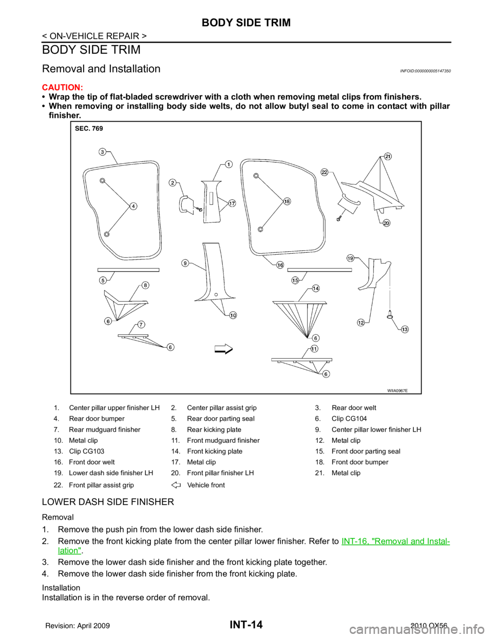
1. Center pillar upper finisher LH 2. Center pillar assist grip 3. Rear door welt
4. Rear door bumper 5. Rear door parting seal 6. Clip CG104
7. Rear mudguard finisher 8. Rear kicking plate 9. Center pillar lower finisher LH
10. Metal clip 11. Front mudguard finisher 12. Metal clip
13. Clip CG103 14. Front kicking plate 15. Front door parting seal
16. Front door welt 17. Metal clip 18. Front door bumper
19. Lower dash side finisher LH 20. Front pillar finisher LH 21. Metal clip
22. Front pillar assist grip Vehicle front
WIIA0967E
Revision: April 20092010 QX56
Page 3659 of 4210
STEERING COLUMNST-21
< REMOVAL AND INSTALLATION >
C
DE
F
H I
J
K L
M A
B
ST
N
O P
4. Remove lock nut and bolt, then separate upper shaft from upper joint.
5. Remove two nuts and two bolts, then remove steering column assembly from steering member.
6. Remove hole cover seal and clamp.
7. Remove nuts, then remove hole cover from dash panel.
8. Raise vehicle, then remove bolt (lower side) of lower joint shaft and remove lower joint shaft and upper shaft as an assembly.
INSPECTION AFTER REMOVAL
• Check for damage to steering column jacket tube. If damage is found, replace steering column with new
one.
• If vehicle has been in a collision, check column length (L), (L
1) and (L2) as shown. If out of specification,
replace steering column with new one.
LGIA0027E
LGIA0028E
LGIA0029E
Steering column length
(L) : Refer to ST-35, "
Steering Column"
(L1): Refer to
ST-35, "Steering Column"
(L2): Refer to
ST-35, "Steering Column"
WGIA0080E
Revision: April 20092010 QX56