Page 2018 of 4210
EXL-42
< COMPONENT DIAGNOSIS >
PARKING LAMP CIRCUIT
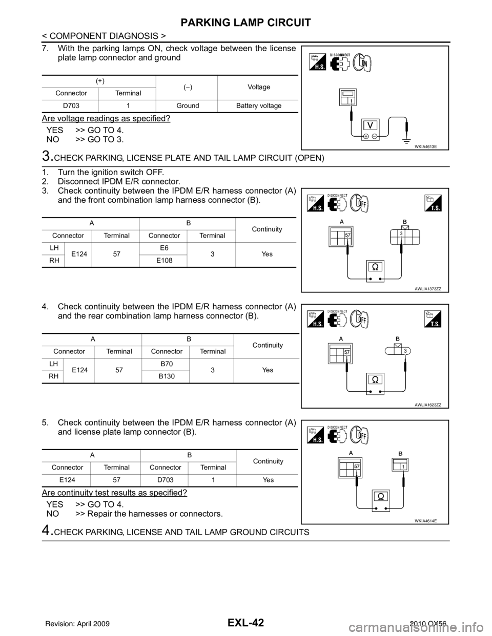
7. With the parking lamps ON, check voltage between the licenseplate lamp connector and ground
Are voltage readings as specified?
YES >> GO TO 4.
NO >> GO TO 3.
3.CHECK PARKING, LICENSE PLATE AND TAIL LAMP CIRCUIT (OPEN)
1. Turn the ignition switch OFF.
2. Disconnect IPDM E/R connector.
3. Check continuity between the IPDM E/R harness connector (A) and the front combination lamp harness connector (B).
4. Check continuity between the IPDM E/R harness connector (A) and the rear combination lamp harness connector (B).
5. Check continuity between the IPDM E/R harness connector (A) and license plate lamp connector (B).
Are continuity test results as specified?
YES >> GO TO 4.
NO >> Repair the harnesses or connectors.
4.CHECK PARKING, LICENSE A ND TAIL LAMP GROUND CIRCUITS
(+)
(−)Voltage
Connector Terminal
D703 1 Ground Battery voltage
WKIA4613E
AB Continuity
Connector Terminal Connector Terminal
LH E124 57 E6
3Y es
RH E108
AWLIA1373ZZ
AB
Continuity
Connector Terminal Connector Terminal
LH E124 57 B70
3Yes
RH B130
AWLIA1623ZZ
AB
Continuity
Connector Terminal Connector Terminal
E124 57D703 1Yes
WKIA4614E
Revision: April 20092010 QX56
Page 2020 of 4210
EXL-44
< COMPONENT DIAGNOSIS >
TURN SIGNAL LAMP CIRCUIT
TURN SIGNAL LAMP CIRCUIT
DescriptionINFOID:0000000005146654
The BCM monitors inputs from the combination switch (lighting and turn signal switch) to determine when to
activate the turn signals. The BCM outputs voltage direction to the left and right turn signals during turn signal
operation or both during hazard warning operation. The BCM sends a turn signal indicator request to the com-
bination meter via the CAN communication lines.
The BCM performs the fast flasher operation (fail-safe) if any bulb or harness of the turn signal lamp circuit is
open.
NOTE:
Turn signal lamp blinks at normal speed when using the hazard warning lamp.
Component Function CheckINFOID:0000000005146655
1.CHECK TURN SIGNAL LAMP
CONSULT-III
1. Select "FLASHER" of BCM (FLASHER) active test item.
2. With operating the test items, check that the turn signal lamp blinks.
Does the turn signal lamp blink?
YES >> Turn signal lamp circuit is normal.
NO >> Refer to EXL-44, "
Diagnosis Procedure".
Diagnosis ProcedureINFOID:0000000005146656
Regarding Wiring Diagram information, refer to EXL-77, "Wiring Diagram".
1.CHECK TURN SIGNAL LAMP BULB
Check the applicable lamp bulb to be sure the proper bulb standard is in use and the bulb is not open.
Is the bulb OK?
YES >> GO TO 2.
NO >> Replace the bulb.
2.CHECK TURN SIGNAL LAMP OUTPUT VOLTAGE
1. Turn the ignition switch OFF.
2. Disconnect the front turn/fog lamp connector or the rear combi- nation lamp connector.
3. Turn the ignition switch ON.
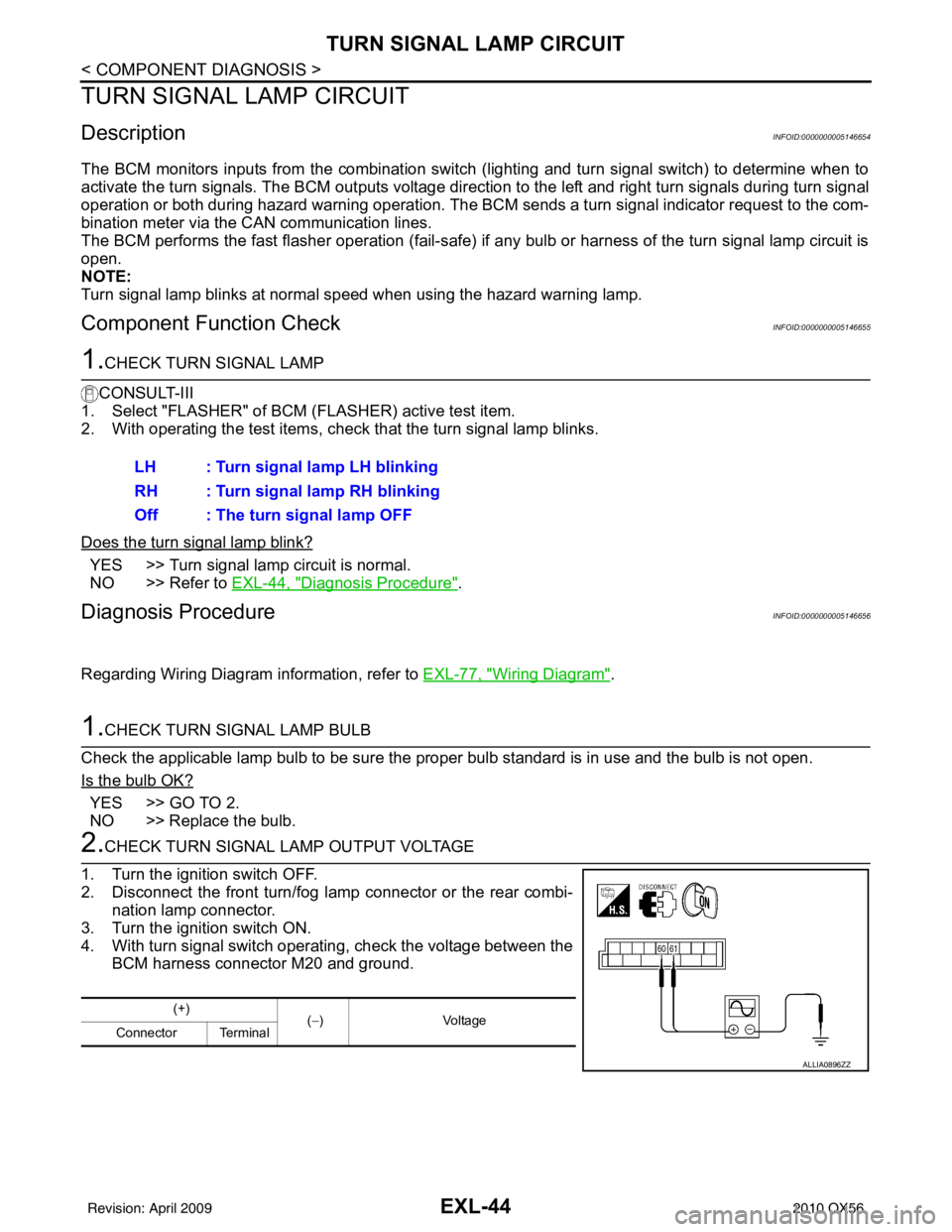
4. With turn signal switch operating, check the voltage between the BCM harness connector M20 and ground.LH : Turn signal lamp LH blinking
RH : Turn signal lamp RH blinking
Off : The turn signal lamp OFF
(+)
(−) Voltage
Connector Terminal
ALLIA0896ZZ
Revision: April 20092010 QX56
Page 2021 of 4210
TURN SIGNAL LAMP CIRCUITEXL-45
< COMPONENT DIAGNOSIS >
C
DE
F
G H
I
J
K
M A
B
EXL
N
O P
Is voltage reading as specified?
YES >> GO TO 3.
NO >> Replace BCM. Refer to BCS-59, "
Removal and Installation".
3.CHECK TURN SIGNAL LAMP CIRCUIT FOR OPEN
1. Turn the ignition switch OFF.
2. Disconnect BCM connector M20.
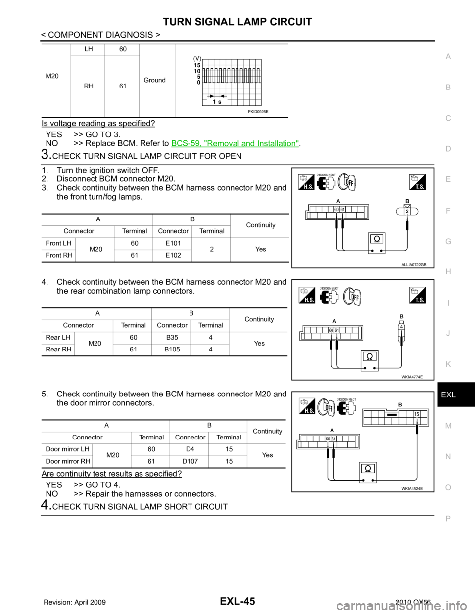
3. Check continuity between the BCM harness connector M20 and the front turn/fog lamps.
4. Check continuity between the BCM harness connector M20 and the rear combination lamp connectors.
5. Check continuity between the BCM harness connector M20 and the door mirror connectors.
Are continuity test results as specified?
YES >> GO TO 4.
NO >> Repair the harnesses or connectors.
4.CHECK TURN SIGNAL LAMP SHORT CIRCUIT
M20 LH 60
Ground
RH 61
PKID0926E
AB Continuity
Connector Terminal Connector Terminal
Front LH M2060 E101
2Yes
Front RH 61 E102
ALLIA0722GB
AB Continuity
Connector Terminal Connector Terminal
Rear LH M2060 B35 4
Ye s
Rear RH 61 B105 4
WKIA4774E
AB
Continuity
Connector Terminal Connector Terminal
Door mirror LH M2060 D4 15
Ye s
Door mirror RH 61 D107 15
WKIA4524E
Revision: April 20092010 QX56
Page 2023 of 4210
OPTICAL SENSOREXL-47
< COMPONENT DIAGNOSIS >
C
DE
F
G H
I
J
K
M A
B
EXL
N
O P
OPTICAL SENSOR
DescriptionINFOID:0000000005146657
The optical sensor converts the outside brightness (lux) to voltage and transmits the optical sensor signal to
the BCM.
Component Function CheckINFOID:0000000005146658
1.CHECK OPTICAL SENSOR SIGNAL BY CONSULT-III
CONSULT-III
1. Turn the ignition switch ON.
2. Select "OPTICAL SENSOR" of BC M (HEAD LAMP) DATA MONITOR item.
3. Turn the lighting switch to AUTO.
4. With the optical sensor illuminat ing, check the monitor status.
*: Illuminates the optical sensor. The value may be less than the standard value if brightness is weak.
Is the item status normal?
YES >> Optical sensor is normal.
NO >> Refer to EXL-47, "
Diagnosis Procedure".
Diagnosis ProcedureINFOID:0000000005146659
Regarding Wiring Diagram information, refer to EXL-62, "Wiring Diagram".
1.CHECK OPTICAL SENSOR GROUND CIRCUIT
1. Turn the ignition switch OFF.
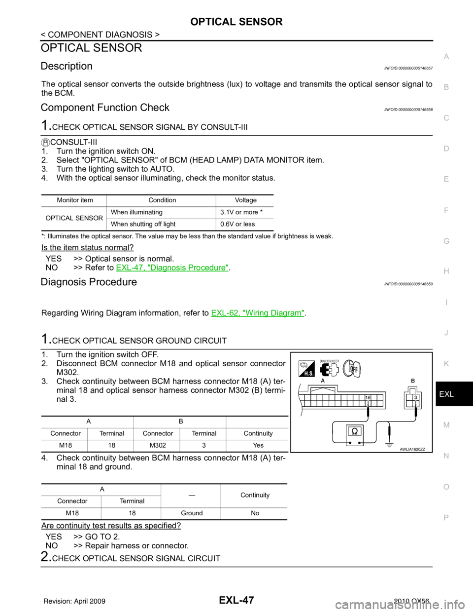
2. Disconnect BCM connector M18 and optical sensor connector M302.
3. Check continuity between BCM harness connector M18 (A) ter-
minal 18 and optical sensor harness connector M302 (B) termi-
nal 3.
4. Check continuity between BCM harness connector M18 (A) ter- minal 18 and ground.
Are continuity test results as specified?
YES >> GO TO 2.
NO >> Repair harness or connector.
2.CHECK OPTICAL SENSOR SIGNAL CIRCUIT
Monitor item ConditionVoltage
OPTICAL SENSOR When illuminating
3.1V or more *
When shutting off light 0.6V or less
AB
Connector Terminal Connector Terminal Continuity M181 8M3023 Y es
A —Contin u it y
Connector Terminal
M18 18Ground No
AWLIA1620ZZ
Revision: April 20092010 QX56
Page 2025 of 4210
HEADLAMP AIMING SWITCHEXL-49
< COMPONENT DIAGNOSIS >
C
DE
F
G H
I
J
K
M A
B
EXL
N
O P
HEADLAMP AIMING SWITCH
DescriptionINFOID:0000000005146660
The manual headlamp aiming system uses a headlamp aiming switch to adjust the axis of the headlamp aim-
ing motor. The headlamp aiming switch has four settings, each with a different resistance value. The head-
lamp aiming motor adjusts to the proper axis based off the position of the headlamp aiming switch.
Diagnosis Procedure - Without Daytime Light SystemINFOID:0000000005146661
Regarding Wiring Diagram information, refer to EXL-69, "Wiring Diagram".
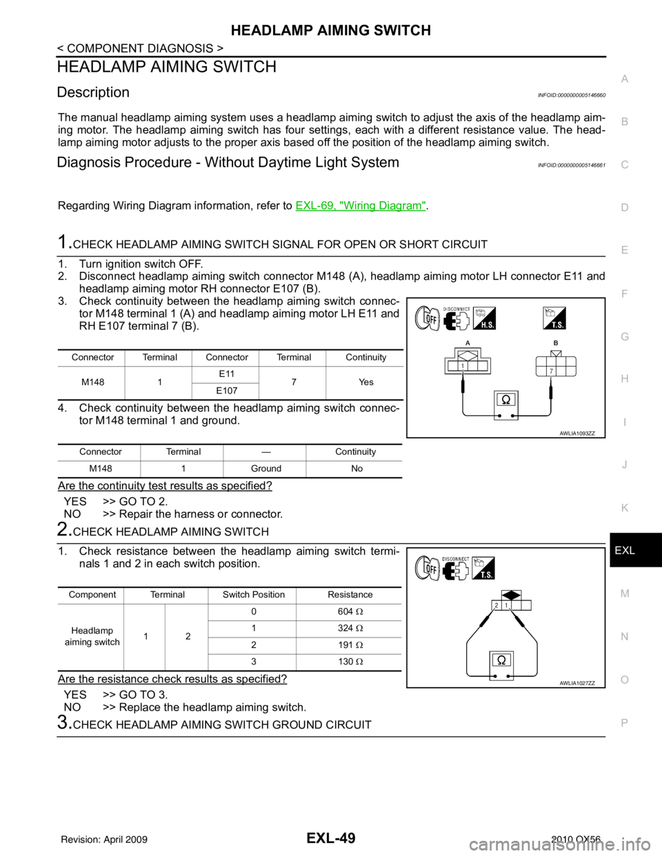
1.CHECK HEADLAMP AIMING SWITCH SIGNAL FOR OPEN OR SHORT CIRCUIT
1. Turn ignition switch OFF.
2. Disconnect headlamp aiming switch connector M148 (A), headlamp aiming motor LH connector E11 and
headlamp aiming motor RH connector E107 (B).
3. Check continuity between the headlamp aiming switch connec-
tor M148 terminal 1 (A) and headlamp aiming motor LH E11 and
RH E107 terminal 7 (B).
4. Check continuity between the headlamp aiming switch connec- tor M148 terminal 1 and ground.
Are the continuity test results as specified?
YES >> GO TO 2.
NO >> Repair the harness or connector.
2.CHECK HEADLAMP AIMING SWITCH
1. Check resistance between the headlamp aiming switch termi- nals 1 and 2 in each switch position.
Are the resistance check results as specified?
YES >> GO TO 3.
NO >> Replace the headlamp aiming switch.
3.CHECK HEADLAMP AIMING SWITCH GROUND CIRCUIT
Connector Terminal Connector Terminal Continuity
M148 1E11
7Y es
E107
Connector Terminal —Continuity
M148 1Ground No
AWLIA1093ZZ
Component Terminal Switch Position Resistance
Headlamp
aiming switch 12 06
04 Ω
13 24 Ω
21 91 Ω
31 30 Ω
AWLIA1027ZZ
Revision: April 20092010 QX56
Page 2026 of 4210
EXL-50
< COMPONENT DIAGNOSIS >
HEADLAMP AIMING SWITCH
1. Turn the ignition switch OFF.
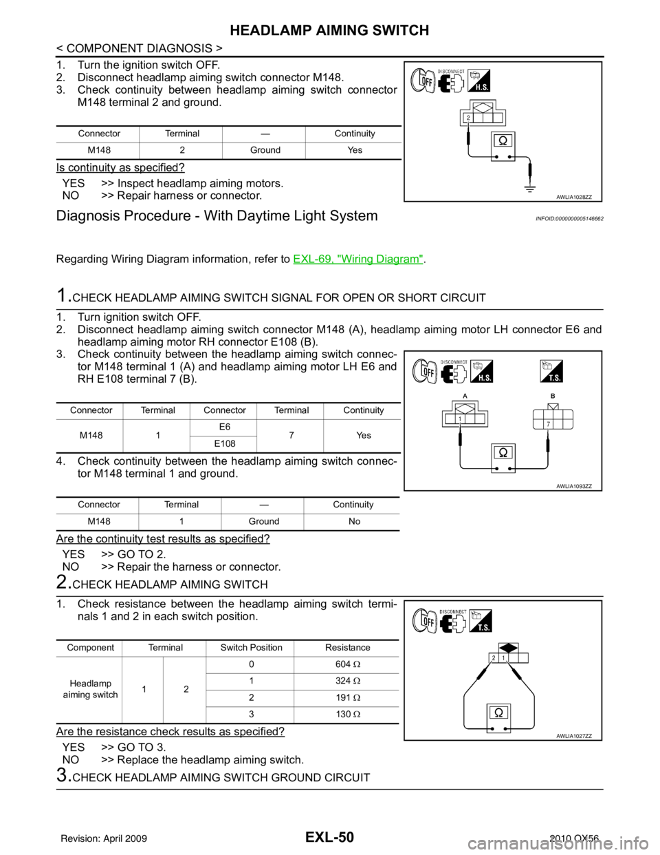
2. Disconnect headlamp aiming switch connector M148.
3. Check continuity between headlamp aiming switch connectorM148 terminal 2 and ground.
Is continuity as specified?
YES >> Inspect headlamp aiming motors.
NO >> Repair harness or connector.
Diagnosis Procedure - With Daytime Light SystemINFOID:0000000005146662
Regarding Wiring Diagram information, refer to EXL-69, "Wiring Diagram".
1.CHECK HEADLAMP AIMING SWITCH SIGNAL FOR OPEN OR SHORT CIRCUIT
1. Turn ignition switch OFF.
2. Disconnect headlamp aiming switch connector M148 (A), headlamp aiming motor LH connector E6 and headlamp aiming motor RH connector E108 (B).
3. Check continuity between the headlamp aiming switch connec-
tor M148 terminal 1 (A) and headlamp aiming motor LH E6 and
RH E108 terminal 7 (B).
4. Check continuity between the headlamp aiming switch connec- tor M148 terminal 1 and ground.
Are the continuity test results as specified?
YES >> GO TO 2.
NO >> Repair the harness or connector.
2.CHECK HEADLAMP AIMING SWITCH
1. Check resistance between the headlamp aiming switch termi- nals 1 and 2 in each switch position.
Are the resistance check results as specified?
YES >> GO TO 3.
NO >> Replace the headlamp aiming switch.
3.CHECK HEADLAMP AIMING SWITCH GROUND CIRCUIT
Connector Terminal —Continuity
M148 2Ground Yes
AWLIA1028ZZ
Connector Terminal Connector Terminal Continuity
M148 1E6
7Y es
E108
Connector Terminal —Continuity
M148 1Ground No
AWLIA1093ZZ
Component Terminal Switch Position Resistance
Headlamp
aiming switch 12 06
04 Ω
13 24 Ω
21 91 Ω
31 30 Ω
AWLIA1027ZZ
Revision: April 20092010 QX56
Page 2027 of 4210
HEADLAMP AIMING SWITCHEXL-51
< COMPONENT DIAGNOSIS >
C
DE
F
G H
I
J
K
M A
B
EXL
N
O P
1. Turn the ignition switch OFF.
2. Disconnect headlamp aiming switch connector M148.
3. Check continuity between headlamp aiming switch connector M148 terminal 2 and ground.
Is continuity as specified?
YES >> Inspect headlamp aiming motors.
NO >> Repair harness or connector.
Connector Terminal —Continuity
M148 2Ground Yes
AWLIA1028ZZ
Revision: April 20092010 QX56
Page 2083 of 4210

BCM (BODY CONTROL MODULE)EXL-107
< ECU DIAGNOSIS >
C
DE
F
G H
I
J
K
M A
B
EXL
N
O P
LIGHT SW 1ST Lighting switch OFF OFF
Lighting switch 1st
ON
HEAD LAMP SW1 Headlamp switch OFF
OFF
Headlamp switch 1st ON
HEAD LAMP SW2 Headlamp switch OFF
OFF
Headlamp switch 1st ON
HI BEAM SW High beam switch OFF
OFF
High beam switch HI ON
IGN ON SW Ignition switch OFF or ACC
OFF
Ignition switch ON ON
IGN SW CAN Ignition switch OFF or ACC
OFF
Ignition switch ON ON
INT VOLUME Wiper intermittent dial is in a dial position 1 - 7 1 - 7
I-KEY LOCK LOCK button of Intelligent Key is not pressed
OFF
LOCK button of Intelligent Key is pressed ON
I-KEY UNLOCK UNLOCK button of Intelligent Key is not pressed
OFF
UNLOCK button of Intelligent Key is pressed ON
KEY CYL LK-SW Door key cylinder LOCK position
ON
Door key cylinder other than LOCK position OF
KEY CYL UN-SW Door key cylinder UNLOCK position
ON
Door key cylinder other than UNLOCK position ON
KEY ON SW Mechanical key is removed from key cylinder
OFF
Mechanical key is inserted to key cylinder ON
OIL PRESS SW • Ignition switch OFF or ACC
• Engine running
OFF
Ignition switch ON ON
OPTICAL SENSOR Bright outside of the vehicle
Close to 5V
Dark outside of the vehicle Close to 0V
PASSING SW Other than lighting switch PASS
OFF
Lighting switch PASS ON
PUSH SW Return to ignition switch to LOCK position
OFF
Press ignition switch ON
REAR DEF SW Rear window defogger switch OFF
OFF
Rear window defogger switch ON ON
RR WASHER SW Rear washer switch OFF
OFF
Rear washer switch ON ON
RR WIPER INT Rear wiper switch OFF
OFF
Rear wiper switch INT ON
RR WIPER ON Rear wiper switch OFF
OFF
Rear wiper switch ON ON
RR WIPER STOP Rear wiper stop position
OFF
Other than rear wiper stop position ON
RR WIPER STP2 Rear wiper stop position
OFF
Other than rear wiper stop position ON
Monitor Item
Condition Value/Status
Revision: April 20092010 QX56