2010 INFINITI QX56 engine
[x] Cancel search: enginePage 2734 of 4210
MA-30
< ON-VEHICLE MAINTENANCE >
CHASSIS AND BODY MAINTENANCE
TRANSFER FLUID
TRANSFER FLUID : ReplacementINFOID:0000000005403153
CAUTION:
If using the vehicle for towing, the transfer fluid must be replaced as specified. Refer to MA-9, "
Intro-
duction of Periodic Maintenance".
DRAINING
1. Stop engine.
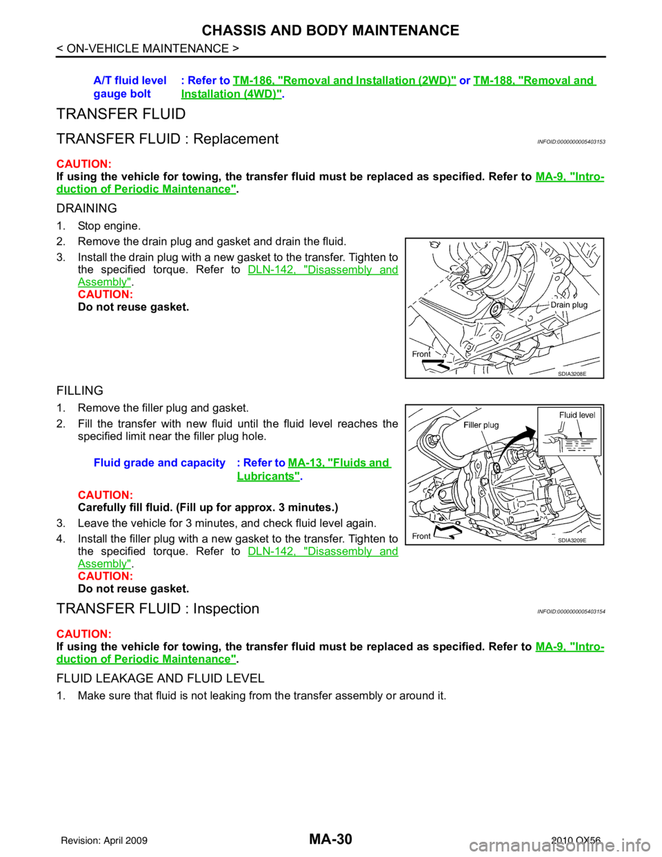
2. Remove the drain plug and gasket and drain the fluid.
3. Install the drain plug with a new gasket to the transfer. Tighten to
the specified torque. Refer to DLN-142, "
Disassembly and
Assembly".
CAUTION:
Do not reuse gasket.
FILLING
1. Remove the filler plug and gasket.
2. Fill the transfer with new fluid until the fluid level reaches the specified limit near the filler plug hole.
CAUTION:
Carefully fill fluid. (Fil l up for approx. 3 minutes.)
3. Leave the vehicle for 3 minutes, and check fluid level again.
4. Install the filler plug with a new gasket to the transfer. Tighten to the specified torque. Refer to DLN-142, "
Disassembly and
Assembly".
CAUTION:
Do not reuse gasket.
TRANSFER FLUID : InspectionINFOID:0000000005403154
CAUTION:
If using the vehicle for towing, the transfer fluid must be replaced as specified. Refer to MA-9, "
Intro-
duction of Periodic Maintenance".
FLUID LEAKAGE AND FLUID LEVEL
1. Make sure that fluid is not leaking from the transfer assembly or around it.A/T fluid level
gauge bolt
: Refer to
TM-186, "
Removal and Installation (2WD)" or TM-188, "Removal and
Installation (4WD)".
SDIA3208E
Fluid grade and capacity : Refer to MA-13, "Fluids and
Lubricants".
SDIA3209E
Revision: April 20092010 QX56
Page 2735 of 4210
CHASSIS AND BODY MAINTENANCEMA-31
< ON-VEHICLE MAINTENANCE >
C
DE
F
G H
I
J
K L
M B
MA
N
O A
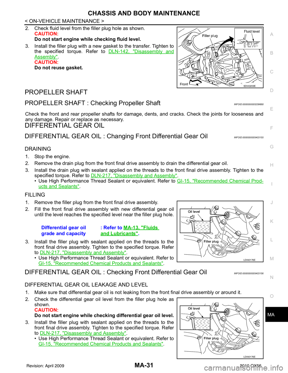
2. Check fluid level from the filler plug hole as shown.
CAUTION:
Do not start engine while checking fluid level.
3. Install the filler plug with a new gasket to the transfer. Tighten to the specified torque. Refer to DLN-142, "
Disassembly and
Assembly".
CAUTION:
Do not reuse gasket.
PROPELLER SHAFT
PROPELLER SHAFT : Checking Propeller ShaftINFOID:0000000005259668
Check the front and rear propeller shafts for damage, dents, and cracks. Check the joints for looseness and
any damage. Repair or replace as necessary.
DIFFERENTIAL GEAR OIL
DIFFERENTIAL GEAR OIL : Changing Front Differential Gear OilINFOID:0000000005403155
DRAINING
1. Stop the engine.
2. Remove the drain plug from the front final drive assembly to drain the differential gear oil.
3. Install the drain plug with sealant applied on the thr eads to the front final drive assembly. Tighten to the
specified torque. Refer to DLN-217, "
Disassembly and Assembly".
• Use High Performance Thread Sealant or equivalent. Refer to GI-15, "
Recommended Chemical Prod-
ucts and Sealants".
FILLING
1. Remove the filler plug from the front final drive assembly.
2. Fill the front final drive assembly with new differential gear oil
until the level reaches the specified level near the filler plug hole.
3. Install the filler plug with sealant applied on the threads to the front final drive assembly. Tighten to the specified torque. Refer
to DLN-217, "
Disassembly and Assembly".
• Use High Performance Thread Sealant or equivalent. Refer to GI-15, "
Recommended Chemical Products and Sealants".
DIFFERENTIAL GEAR OIL : Checking Front Differential Gear OilINFOID:0000000005403156
DIFFERENTIAL GEAR OIL LEAKAGE AND LEVEL
1. Make sure that differential gear oil is not leaking from the front final drive assembly or around it.
2. Check the differential gear oil level from the filler plug hole as
shown.
CAUTION:
Do not start engine while checki ng differential gear oil level.
3. Install the filler plug with sealant applied on the threads to the front final drive assembly. Tighten to the specified torque. Refer
to DLN-217, "
Disassembly and Assembly".
• Use High Performance Thread Sealant or equivalent. Refer to GI-15, "
Recommended Chemical Products and Sealants".
SDIA3209E
Differential gear oil
grade and capacity : Refer to
MA-13, "Fluids
and Lubricants".
LDIA0176E
LDIA0176E
Revision: April 20092010 QX56
Page 2736 of 4210
MA-32
< ON-VEHICLE MAINTENANCE >
CHASSIS AND BODY MAINTENANCE
DIFFERENTIAL GEAR OIL : Changi ng Rear Differential Gear Oil
INFOID:0000000005403157
DRAINING
1. Stop the engine.
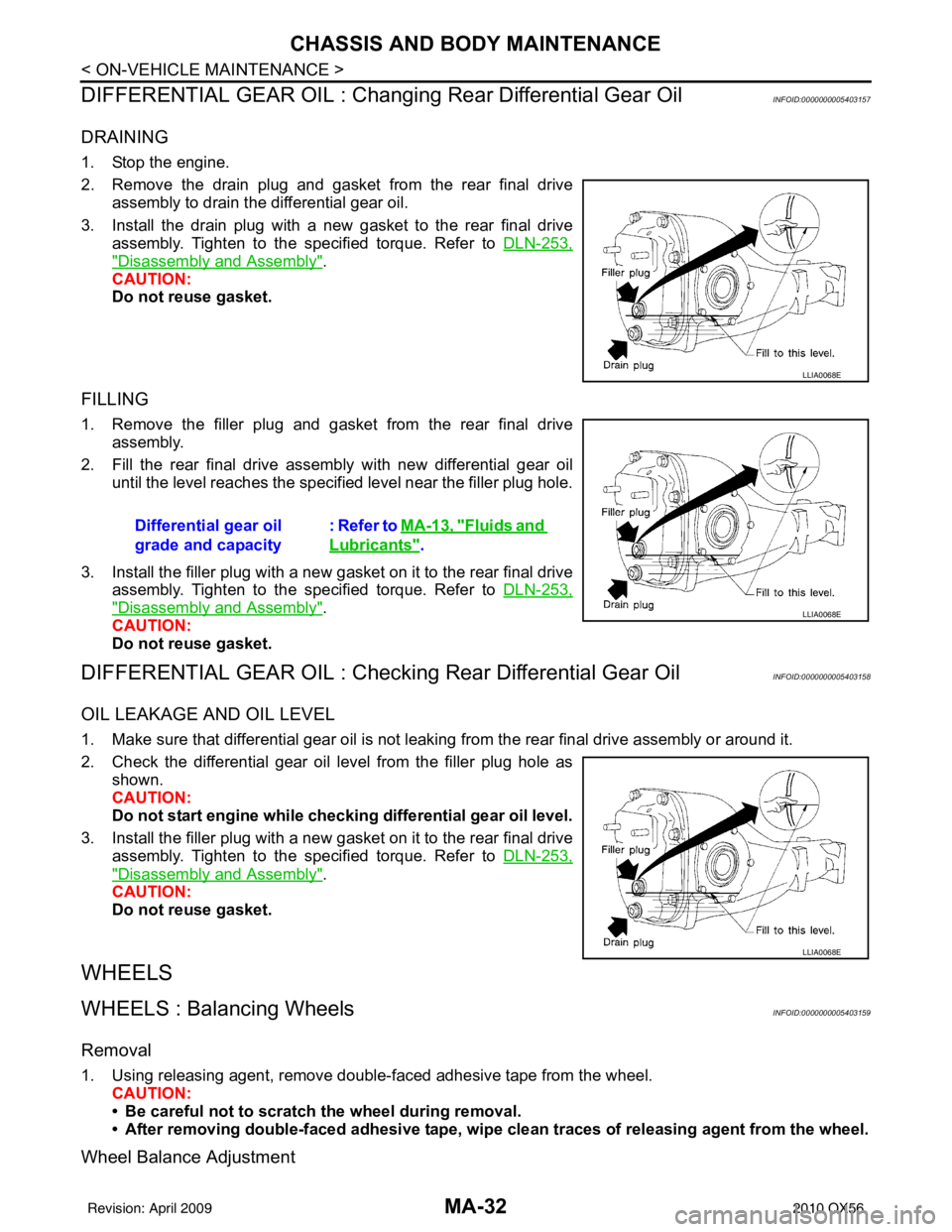
2. Remove the drain plug and gasket from the rear final drive
assembly to drain the differential gear oil.
3. Install the drain plug with a new gasket to the rear final drive assembly. Tighten to the specified torque. Refer to DLN-253,
"Disassembly and Assembly".
CAUTION:
Do not reuse gasket.
FILLING
1. Remove the filler plug and gasket from the rear final drive assembly.
2. Fill the rear final drive assembly with new differential gear oil until the level reaches the specified level near the filler plug hole.
3. Install the filler plug with a new gasket on it to the rear final drive assembly. Tighten to the specified torque. Refer to DLN-253,
"Disassembly and Assembly".
CAUTION:
Do not reuse gasket.
DIFFERENTIAL GEAR OIL : Checking Rear Differential Gear OilINFOID:0000000005403158
OIL LEAKAGE AND OIL LEVEL
1. Make sure that differential gear oil is not leaki ng from the rear final drive assembly or around it.
2. Check the differential gear oil level from the filler plug hole as shown.
CAUTION:
Do not start engine while checki ng differential gear oil level.
3. Install the filler plug with a new gasket on it to the rear final drive assembly. Tighten to the specified torque. Refer to DLN-253,
"Disassembly and Assembly".
CAUTION:
Do not reuse gasket.
WHEELS
WHEELS : Balancing WheelsINFOID:0000000005403159
Removal
1. Using releasing agent, remove double-faced adhesive tape from the wheel. CAUTION:
• Be careful not to scratch the wheel during removal.
• After removing double-faced adh esive tape, wipe clean traces of releasing agent from the wheel.
Wheel Balance Adjustment
LLIA0068E
Differential gear oil
grade and capacity: Refer to MA-13, "Fluids and
Lubricants".
LLIA0068E
LLIA0068E
Revision: April 20092010 QX56
Page 2738 of 4210
MA-34
< ON-VEHICLE MAINTENANCE >
CHASSIS AND BODY MAINTENANCE
Wheel balance (Maximum allowable imbalance):
WHEELS : RotationINFOID:0000000005403160
NOTE:
Follow the maintenance schedule for tire rotation service intervals. Refer to MA-9, "
Schedule 1" .
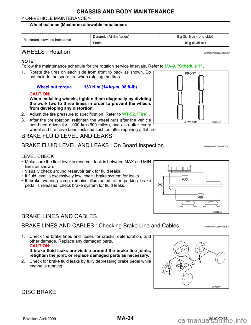
1. Rotate the tires on each side from front to back as shown. Do not include the spare tire when rotating the tires.
CAUTION:
When installing wheel s, tighten them diagonally by dividing
the work two to three times in order to prevent the wheels
from developing any distortion.
2. Adjust the tire pressure to specification. Refer to WT-52, "
Tire" .
3. After the tire rotation, retighten the wheel nuts after the vehicle has been driven for 1,000 km (600 miles), and also after every
wheel and tire have been installed such as after repairing a flat tire.
BRAKE FLUID LEVEL AND LEAKS
BRAKE FLUID LEVEL AND LEAK S : On Board InspectionINFOID:0000000005403161
LEVEL CHECK
• Make sure the fluid level in reservoir tank is between MAX and MIN
lines as shown.
• Visually check around reservoir tank for fluid leaks.
• If fluid level is excessively low, check brake system for leaks.
• If brake warning lamp remains illuminated after parking brake pedal is released, check brake system for fluid leaks.
BRAKE LINES AND CABLES
BRAKE LINES AND CABLES : Ch ecking Brake Line and CablesINFOID:0000000005259676
1. Check the brake lines and hoses for cracks, deterioration, and
other damage. Replace any damaged parts.
CAUTION:
If brake fluid leaks are visible around the brake line joints,
retighten the joint, or replace damaged parts as necessary.
2. Check for brake fluid leaks by fully depressing brake pedal while engine is running.
DISC BRAKE
Maximum allowable imbalance Dynamic (At rim flange) 5 g (0.18 oz) (one side)
Static
10 g (0.35 oz)
Wheel nut torque : 133 N·m (14 kg-m, 98 ft-lb)
SMA829C
LFIA0225E
SBR389C
Revision: April 20092010 QX56
Page 2741 of 4210
CHASSIS AND BODY MAINTENANCEMA-37
< ON-VEHICLE MAINTENANCE >
C
DE
F
G H
I
J
K L
M B
MA
N
O A
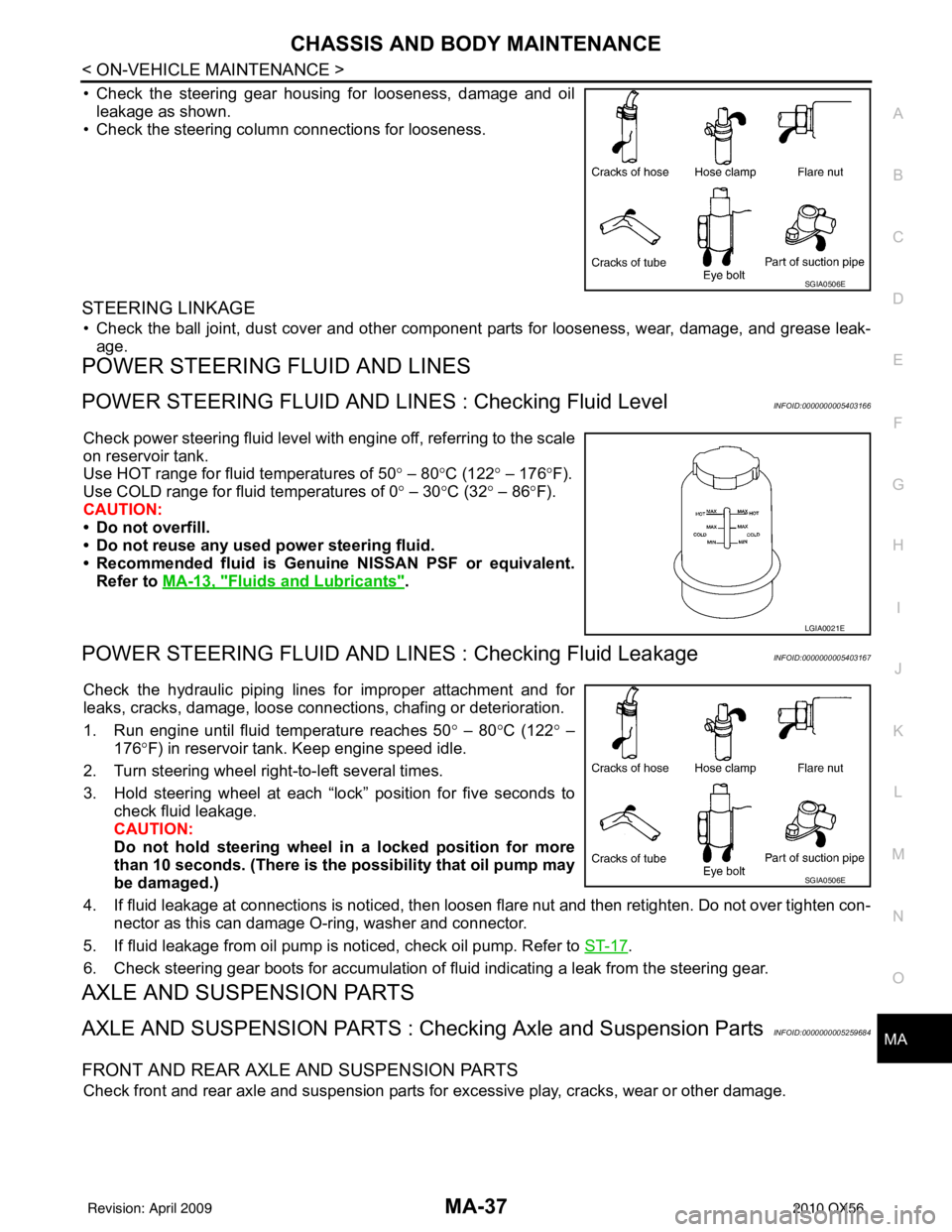
• Check the steering gear housing for looseness, damage and oil
leakage as shown.
• Check the steering column connections for looseness.
STEERING LINKAGE
• Check the ball joint, dust cover and other component parts for looseness, wear, damage, and grease leak-
age.
POWER STEERING FLUID AND LINES
POWER STEERING FLUID AND LINE S : Checking Fluid LevelINFOID:0000000005403166
Check power steering fluid level with engine off, referring to the scale
on reservoir tank.
Use HOT range for fluid temperatures of 50 ° – 80 °C (122 ° – 176 °F).
Use COLD range for fluid temperatures of 0 ° – 30 °C (32° – 86°F).
CAUTION:
• Do not overfill.
• Do not reuse any used power steering fluid.
• Recommended fluid is Genuine NISSAN PSF or equivalent.
Refer to MA-13, "
Fluids and Lubricants".
POWER STEERING FLUID AND LINES : Checking Fluid LeakageINFOID:0000000005403167
Check the hydraulic piping lines for improper attachment and for
leaks, cracks, damage, loose connec tions, chafing or deterioration.
1. Run engine until fluid temperature reaches 50 ° – 80° C (122° –
176° F) in reservoir tank. Keep engine speed idle.
2. Turn steering wheel right-to-left several times.
3. Hold steering wheel at each “lock” position for five seconds to check fluid leakage.
CAUTION:
Do not hold steering wheel in a locked position for more
than 10 seconds. (There is the possibility that oil pump may
be damaged.)
4. If fluid leakage at connections is noticed, then loosen flare nut and then retighten. Do not over tighten con- nector as this can damage O-ring, washer and connector.
5. If fluid leakage from oil pump is noticed, check oil pump. Refer to ST-17
.
6. Check steering gear boots for accumulation of fluid indicating a leak from the steering gear.
AXLE AND SUSPENSION PARTS
AXLE AND SUSPENSION PARTS : Chec king Axle and Suspension PartsINFOID:0000000005259684
FRONT AND REAR AXLE AND SUSPENSION PARTS
Check front and rear axle and suspension parts for excessive play, cracks, wear or other damage.
SGIA0506E
LGIA0021E
SGIA0506E
Revision: April 20092010 QX56
Page 2751 of 4210
MIR-8
< PRECAUTION >
PRECAUTIONS
PRECAUTION
PRECAUTIONS
Precaution for Supplemental Restraint System (SRS) "AIR BAG" and "SEAT BELT
PRE-TENSIONER"
INFOID:0000000005394721
The Supplemental Restraint System such as “A IR BAG” and “SEAT BELT PRE-TENSIONER”, used along
with a front seat belt, helps to reduce the risk or severity of injury to the driver and front passenger for certain
types of collision. This system includes seat belt switch inputs and dual stage front air bag modules. The SRS
system uses the seat belt switches to determine the front air bag deployment, and may only deploy one front
air bag, depending on the severity of a collision and w hether the front occupants are belted or unbelted.
Information necessary to service the system safely is included in the SR and SB section of this Service Man-
ual.
WARNING:
• To avoid rendering the SRS inopera tive, which could increase the risk of personal injury or death in
the event of a collision which would result in air bag inflation, all maintenance must be performed by
an authorized NISSAN/INFINITI dealer.
• Improper maintenance, including in correct removal and installation of the SRS, can lead to personal
injury caused by unintent ional activation of the system. For re moval of Spiral Cable and Air Bag
Module, see the SR section.
• Do not use electrical test equipmen t on any circuit related to the SRS unless instructed to in this
Service Manual. SRS wiring harn esses can be identified by yellow and/or orange harnesses or har-
ness connectors.
PRECAUTIONS WHEN USING POWER TOOLS (AIR OR ELECTRIC) AND HAMMERS
WARNING:
• When working near the Airbag Diagnosis Sensor Unit or other Airbag System sensors with the Igni-
tion ON or engine running, DO NOT use air or electri c power tools or strike near the sensor(s) with a
hammer. Heavy vibration could activate the sensor( s) and deploy the air bag(s), possibly causing
serious injury.
• When using air or electric power tools or hammers , always switch the Ignition OFF, disconnect the
battery, and wait at least 3 minu tes before performing any service.
Precaution Necessary for Steering W heel Rotation After Battery Disconnect
INFOID:0000000005369282
NOTE:
• This Procedure is applied only to models with Intelligent Key system and NATS (NISSAN ANTI-THEFT SYS-
TEM).
• Remove and install all control units after disconnecting both battery cables with the ignition knob in the
″LOCK ″ position.
• Always use CONSULT-III to perform self-diagnosis as a part of each function inspection after finishing work.
If DTC is detected, perform trouble diagnosis according to self-diagnostic results.
For models equipped with the Intelligent Key system and NATS, an electrically controlled steering lock mech-
anism is adopted on the key cylinder.
For this reason, if the battery is disconnected or if the battery is discharged, the steering wheel will lock and
steering wheel rotation will become impossible.
If steering wheel rotation is required when battery pow er is interrupted, follow the procedure below before
starting the repair operation.
OPERATION PROCEDURE
1. Connect both battery cables. NOTE:
Supply power using jumper cables if battery is discharged.
2. Use the Intelligent Key or mechanical key to turn the ignition switch to the ″ACC ″ position. At this time, the
steering lock will be released.
3. Disconnect both battery cables. The steering lock will remain released and the steering wheel can be rotated.
4. Perform the necessary repair operation.
Revision: April 20092010 QX56
Page 2753 of 4210
MIR-10
< PREPARATION >
PREPARATION
PREPARATION
PREPARATION
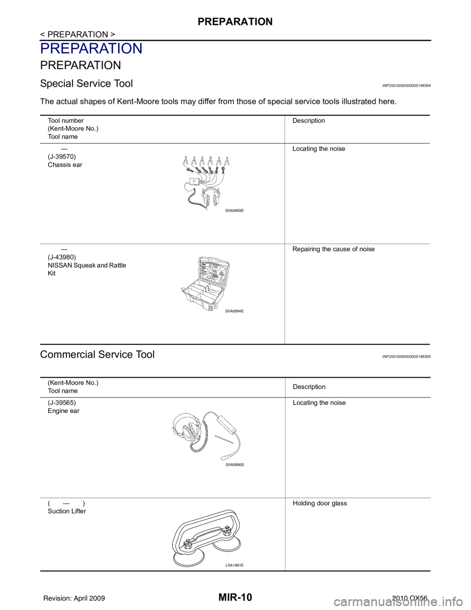
Special Service ToolINFOID:0000000005146594
The actual shapes of Kent-Moore tools may differ from those of special service tools illustrated here.
Commercial Service ToolINFOID:0000000005146595
Tool number
(Kent-Moore No.)
Tool name Description
—
(J-39570)
Chassis ear Locating the noise
—
(J-43980)
NISSAN Squeak and Rattle
Kit Repairing the cause of noise
SIIA0993E
SIIA0994E
(Kent-Moore No.)
Tool name
Description
(J-39565)
Engine ear Locating the noise
(—)
Suction Lifter Holding door glass
SIIA0995E
LIIA1991E
Revision: April 20092010 QX56
Page 2763 of 4210
MWI
MWI-1
DRIVER INFORMATION & MULTIMEDIA
C
DE
F
G H
I
J
K L
M B
SECTION MWI
A
O P
CONTENTS
METER, WARNING LAMP & INDICATOR
BASIC INSPECTION ....... .............................4
DIAGNOSIS AND REPAIR WORKFLOW ..... .....4
Work Flow ........................................................... ......4
FUNCTION DIAGNOSIS ...............................5
METER SYSTEM ............................................ .....5
METER SYSTEM .........................................................5
METER SYSTEM : System Diagram ........................5
METER SYSTEM : System Description ....................5
METER SYSTEM : Arrangem ent of Combination
Meter ................................................................... ......
6
METER SYSTEM : Component Parts Location ........7
METER SYSTEM : Component Description ....... ......7
SPEEDOMETER ..........................................................8
SPEEDOMETER : System Diagram ................... ......8
SPEEDOMETER : System Description .....................8
SPEEDOMETER : Component Parts Location .........9
SPEEDOMETER : Component Description ........ ......9
TACHOMETER ...................................................... ......9
TACHOMETER : System Diagram ...........................9
TACHOMETER : System De scription .....................10
TACHOMETER : Component Parts Location ..... ....10
TACHOMETER : Component Description ..............10
ENGINE COOLANT TEMPERATURE GAUGE .... ....10
ENGINE COOLANT TEMPERATURE GAUGE :
System Diagram ......................................................
11
ENGINE COOLANT TEMPERATURE GAUGE :
System Description .................................................
11
ENGINE COOLANT TEMPERATURE GAUGE :
Component Parts Location ......................................
11
ENGINE COOLANT TEMPERATURE GAUGE :
Component Description ...........................................
12
FUEL GAUGE ........................................................ ....12
FUEL GAUGE : System Diagram ...........................12
FUEL GAUGE : System Description .......................12
FUEL GAUGE : Component Parts Location ...........12
FUEL GAUGE : Component Description ............. ....13
ENGINE OIL PRESSURE GAUGE ............................13
ENGINE OIL PRESSURE GAUGE : System Dia-
gram .................................................................... ....
13
ENGINE OIL PRESSURE GAUGE : System De-
scription ...................................................................
13
ENGINE OIL PRESSURE GAUGE : Component
Parts Location ..........................................................
14
ENGINE OIL PRESSURE GAUGE : Component
Description ...............................................................
14
VOLTAGE GAUGE ................................................ ....14
VOLTAGE GAUGE : System Diagram ....................15
VOLTAGE GAUGE : System Description ................15
VOLTAGE GAUGE : Component Parts Location ....15
VOLTAGE GAUGE : Component Description .........16
ODO/TRIP METER ................................................. ....16
ODO/TRIP METER : System Diagram ....................16
ODO/TRIP METER : System Description ................16
ODO/TRIP METER : Component Parts Location ....16
ODO/TRIP METER : Component Description .........17
SHIFT POSITION INDICATOR .............................. ....17
SHIFT POSITION INDICATOR : System Diagram ....17
SHIFT POSITION INDICATOR : System Descrip-
tion ...........................................................................
17
SHIFT POSITION INDICATOR : Component
Parts Location ..........................................................
18
SHIFT POSITION INDICATOR : Component De-
scription ............................................................... ....
18
WARNING LAMPS/INDICATOR LAMPS .............. ....18
WARNING LAMPS/INDICATOR LAMPS : System
Diagram ............................................................... ....
18
WARNING LAMPS/INDICATOR LAMPS : System
Description ........................................................... ....
19
WARNING LAMPS/INDICATOR LAMPS : Com-
ponent Parts Location ..............................................
19
WARNING LAMPS/INDICATOR LAMPS : Com-
ponent Description ...................................................
19
Revision: April 20092010 QX56