Page 1854 of 4210
PRECAUTIONSEM-3
< PRECAUTION >
C
DE
F
G H
I
J
K L
M A
EM
NP
O
PRECAUTION
PRECAUTIONS
Precaution for Supplemental
Restraint System (SRS) "AIR BAG" and "SEAT BELT
PRE-TENSIONER"
INFOID:0000000005259661
The Supplemental Restraint System such as “AIR BAG” and “SEAT BELT PRE-TENSIONER”, used along
with a front seat belt, helps to reduce the risk or severi ty of injury to the driver and front passenger for certain
types of collision. This system includes seat belt switch inputs and dual stage front air bag modules. The SRS
system uses the seat belt switches to determine the front air bag deployment, and may only deploy one front
air bag, depending on the severity of a collision and w hether the front occupants are belted or unbelted.
Information necessary to service the system safely is included in the SR and SB section of this Service Man-
ual.
WARNING:
• To avoid rendering the SRS inoper ative, which could increase the risk of personal injury or death in
the event of a collision which would result in air bag inflation, all maintenance must be performed by
an authorized NISSAN/INFINITI dealer.
• Improper maintenance, including in correct removal and installation of the SRS, can lead to personal
injury caused by unintentional act ivation of the system. For removal of Spiral Cable and Air Bag
Module, see the SR section.
• Do not use electrical test equipm ent on any circuit related to the SRS unless instructed to in this
Service Manual. SRS wiring harnesses can be identi fied by yellow and/or orange harnesses or har-
ness connectors.
PRECAUTIONS WHEN USING POWER TOOLS (AIR OR ELECTRIC) AND HAMMERS
WARNING:
• When working near the Airbag Diagnosis Sensor Un it or other Airbag System sensors with the Igni-
tion ON or engine running, DO NOT use air or el ectric power tools or strike near the sensor(s) with a
hammer. Heavy vibration could activate the sensor( s) and deploy the air bag(s), possibly causing
serious injury.
• When using air or electric power tools or hammers, always switch the Ignition OFF, disconnect the battery, and wait at least 3 minutes before performing any service.
Precaution Necessary for Steering Wheel Rotation After Battery Disconnect
INFOID:0000000005260133
NOTE:
• This Procedure is applied only to models with Intelligent Key system and NATS (NISSAN ANTI-THEFT SYS-
TEM).
• Remove and install all control units after disconnecti ng both battery cables with the ignition knob in the
″ LOCK ″ position.
• Always use CONSULT-III to perform self-diagnosis as a part of each function inspection after finishing work.
If DTC is detected, perform trouble diagnosis according to self-diagnostic results.
For models equipped with the Intelligent Key system and NATS , an electrically controlled steering lock mech-
anism is adopted on the key cylinder.
For this reason, if the battery is disconnected or if the battery is discharged, the steering wheel will lock and
steering wheel rotation will become impossible.
If steering wheel rotation is required when battery power is interrupted, follow the procedure below before
starting the repair operation.
OPERATION PROCEDURE
1. Connect both battery cables. NOTE:
Supply power using jumper cables if battery is discharged.
2. Use the Intelligent Key or mechanical key to turn the ignition switch to the ″ACC ″ position. At this time, the
steering lock will be released.
3. Disconnect both battery cables. The steering lock will remain released and the steering wheel can be
rotated.
4. Perform the necessary repair operation.
Revision: April 20092010 QX56
Page 1864 of 4210
DRIVE BELTSEM-13
< ON-VEHICLE MAINTENANCE >
C
DE
F
G H
I
J
K L
M A
EM
NP
O
ON-VEHICLE MAINTENANCE
DRIVE BELTS
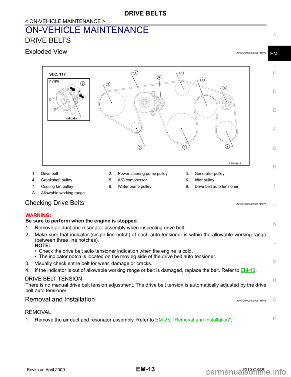
Exploded ViewINFOID:0000000005148974
Checking Drive BeltsINFOID:0000000005148975
WARNING:
Be sure to perform when the engine is stopped.
1. Remove air duct and resonator assembly when inspecting drive belt.
2. Make sure that indicator (single line notch) of eac
h auto tensioner is within the allowable working range
(between three line notches).
NOTE:
• Check the drive belt auto tensioner indication when the engine is cold.
• The indicator notch is located on the moving side of the drive belt auto tensioner.
3. Visually check entire belt for wear, damage or cracks.
4. If the indicator is out of allowable working range or belt is damaged, replace the belt. Refer to EM-13
.
DRIVE BELT TENSION
There is no manual drive belt tension adjustment. The driv e belt tension is automatically adjusted by the drive
belt auto tensioner.
Removal and InstallationINFOID:0000000005148976
REMOVAL
1. Remove the air duct and resonator assembly. Refer to EM-25, "Removal and Installation".
1. Drive belt2. Power steering pump pulley 3. Generator pulley
4. Crankshaft pulley 5. A/C compressor6. Idler pulley
7. Cooling fan pulley 8. Water pump pulley9. Drive belt auto tensioner
A. Allowable working range
LBIA0391E
Revision: April 20092010 QX56
Page 1865 of 4210
EM-14
< ON-VEHICLE MAINTENANCE >
DRIVE BELTS
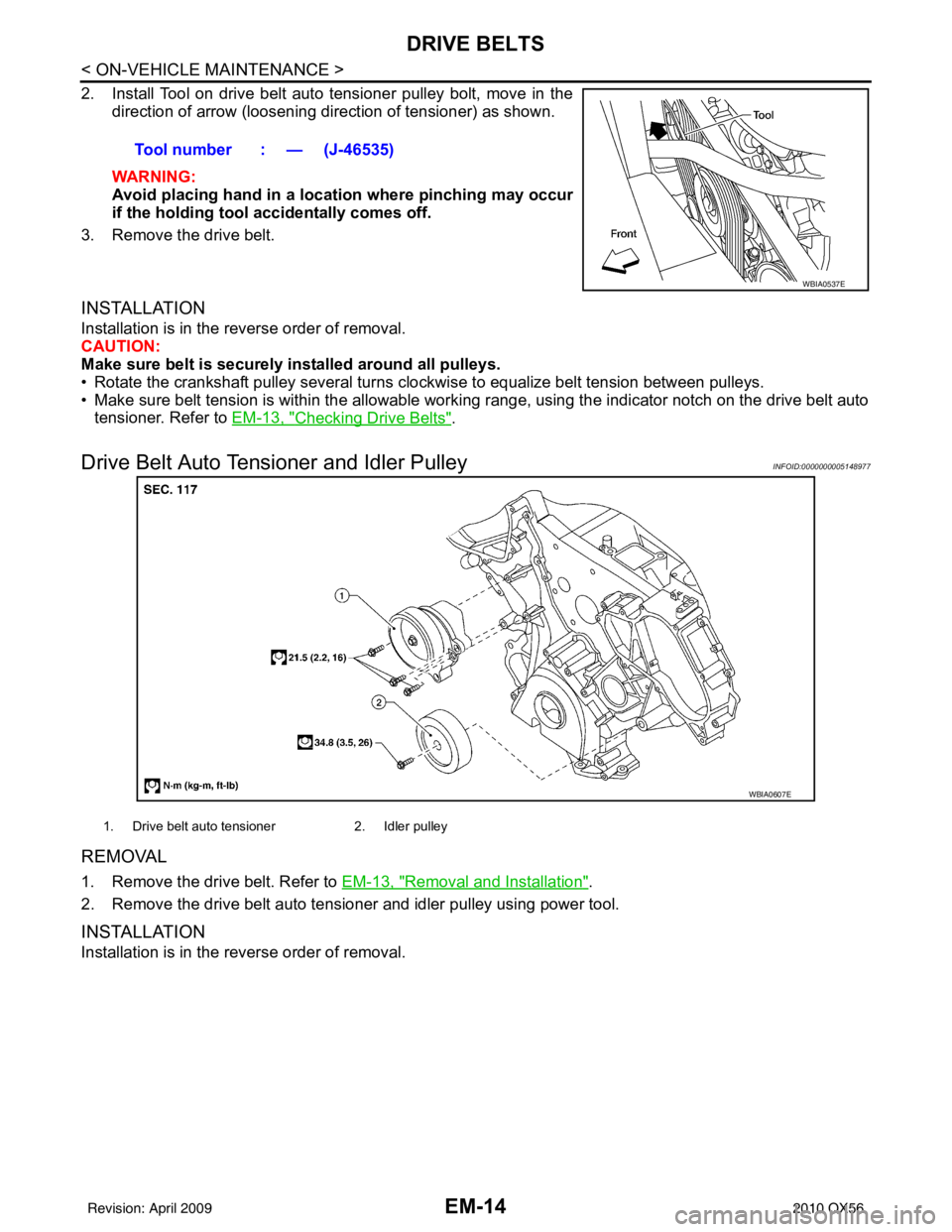
2. Install Tool on drive belt auto tensioner pulley bolt, move in thedirection of arrow (loosening direction of tensioner) as shown.
WARNING:
Avoid placing hand in a locatio n where pinching may occur
if the holding tool accidentally comes off.
3. Remove the drive belt.
INSTALLATION
Installation is in the reverse order of removal.
CAUTION:
Make sure belt is securely installed around all pulleys.
• Rotate the crankshaft pulley several turns clockwise to equalize belt tension between pulleys.
• Make sure belt tension is within the allowable working range, using the indicator notch on the drive belt auto tensioner. Refer to EM-13, "
Checking Drive Belts".
Drive Belt Auto Tensioner and Idler PulleyINFOID:0000000005148977
REMOVAL
1. Remove the drive belt. Refer to EM-13, "Removal and Installation".
2. Remove the drive belt auto tensioner and idler pulley using power tool.
INSTALLATION
Installation is in the reverse order of removal. Tool number : — (J-46535)
WBIA0537E
WBIA0607E
1. Drive belt auto tensioner
2. Idler pulley
Revision: April 20092010 QX56
Page 1866 of 4210
AIR CLEANER FILTEREM-15
< ON-VEHICLE MAINTENANCE >
C
DE
F
G H
I
J
K L
M A
EM
NP
O
AIR CLEANER FILTER
Exploded ViewINFOID:0000000005148978
Removal and Installation (Viscous paper type)INFOID:0000000005148979
REMOVAL
NOTE:
• The viscous paper type filter does not
need cleaning between replacement intervals.
• Replace the air filter as necessary for periodic maintenance. Refer to MA-9, "
Introduction of Periodic Mainte-
nance".
1. Remove the air cleaner case (upper).
2. Remove the air cleaner filter from the air cleaner case (lower).
INSTALLATION
1. Install the new air cleaner filter in the air cleaner case (lower).
2. Install the air cleaner case (upper).
1. Air cleaner case (lower) 2. Air cleaner filter3. Air cleaner case (upper)
4. Air duct and resonator assembly Front
ALBIA0413GB
Revision: April 20092010 QX56
Page 1867 of 4210
EM-16
< ON-VEHICLE MAINTENANCE >
SPARK PLUG
SPARK PLUG
Exploded ViewINFOID:0000000005148980
Removal and InstallationINFOID:0000000005148981
REMOVAL
1. Disconnect the harness connector from the ignition coil.
2. Remove ignition coil. CAUTION:
Do not shock ig nition coil.
3. Remove spark plug using suitable tool.
INSPECTION AFTER REMOVAL
• Do not use a wire brush for cleaning.
• If plug tip is covered with carbon, spark plug cleaner may be used.
1. Ignition coil 2. Spark plug
WBIA0796E
SEM294A
Cleaner air pressure:
Less than 588 kPa (5.9 bar, 6 kg/cm
2, 85 psi)
Cleaning time: Less than 20 seconds
SMA773C
Revision: April 20092010 QX56
Page 1868 of 4210
SPARK PLUGEM-17
< ON-VEHICLE MAINTENANCE >
C
DE
F
G H
I
J
K L
M A
EM
NP
O
• Checking and adjusting plug gap is not required between change
intervals.
INSTALLATION
Installation is in the reverse order of removal.
Spark Plug Types
CAUTION:
Do not drop or shock spark plug.
SMA806CA
Make NGK
Model Standard model
Standard type DILFR5A-11
Gap (Nominal) 1.1 mm (0.043 in)
Revision: April 20092010 QX56
Page 1869 of 4210
EM-18
< ON-VEHICLE MAINTENANCE >
CAMSHAFT VALVE CLEARANCE
CAMSHAFT VALVE CLEARANCE
Valve ClearanceINFOID:0000000005148982
INSPECTION
NOTE:
Perform the following inspection after removal, installation or replacement of camshaft or valve-related parts,
or if there are unusual engine conditions due to changes in valve clearance over time (starting, idling, and/or
noise).
1. Warm up the engine. Then stop the engine.
2. Remove the engine room cover. Refer to EM-24, "
Removal and Installation".
3. Remove the air cleaner and air duct assembly. Refer to EM-25, "
Removal and Installation".
4. Remove the RH bank and LH bank rocker covers using power tool. Refer to EM-38, "
Removal and Instal-
lation".
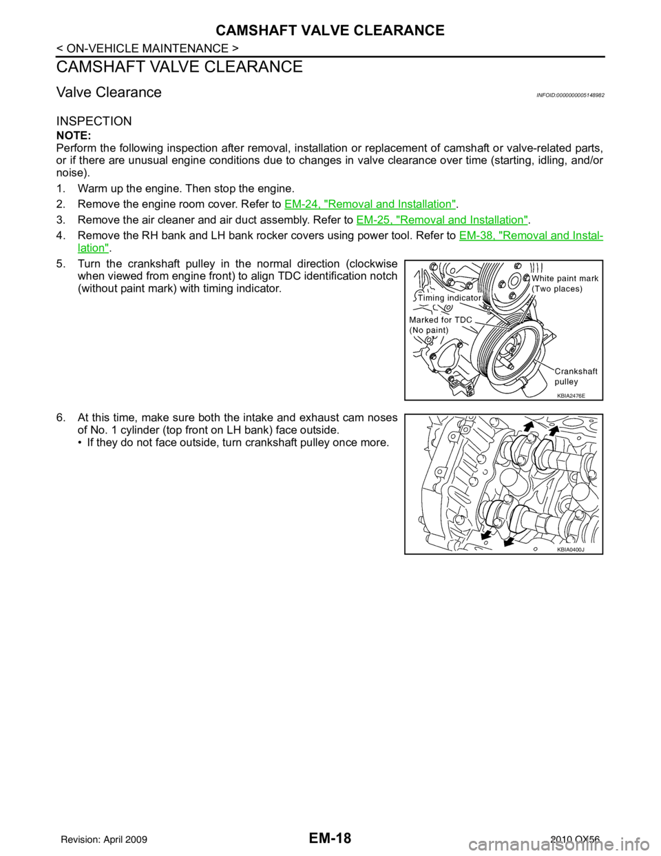
5. Turn the crankshaft pulley in the normal direction (clockwise when viewed from engine front) to align TDC identification notch
(without paint mark) with timing indicator.
6. At this time, make sure both the intake and exhaust cam noses of No. 1 cylinder (top front on LH bank) face outside.
• If they do not face outside, turn crankshaft pulley once more.
KBIA2476E
KBIA0400J
Revision: April 20092010 QX56
Page 1870 of 4210
CAMSHAFT VALVE CLEARANCEEM-19
< ON-VEHICLE MAINTENANCE >
C
DE
F
G H
I
J
K L
M A
EM
NP
O
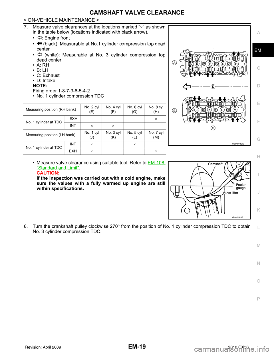
7. Measure valve clearances at the locations marked “×
” as shown
in the table below (locations indicated with black arrow).
• : Engine front
• (black): Measurable at No.1 cylinder compression top dead center
• (white): Measurable at No. 3 cylinder compression top dead center
•A: RH
•B: LH
• C: Exhaust
• D: Intake
NOTE:
Firing order 1-8-7-3-6-5-4-2
• No. 1 cylinder compression TDC
• Measure valve clearance using suitable tool. Refer to EM-108,
"Standard and Limit".
CAUTION:
If the inspection was carried out with a cold engine, make
sure the values with a fully warmed up engine are still
within specifications.
8. Turn the crankshaft pulley clockwise 270 ° from the position of No. 1 cylinder compression TDC to obtain
No. 3 cylinder compression TDC.
Measuring position (RH bank) No. 2 cyl
(E) No. 4 cyl
(F) No. 6 cyl
(G) No. 8 cyl
(H)
No. 1 cylinder at TDC EXH
×
INT ××
Measuring position (LH bank) No. 1 cyl
(J) No. 3 cyl
(K) No. 5 cyl
(L) No. 7 cyl
(M)
No. 1 cylinder at TDC INT
××
EXH ××
WBIA0713E
KBIA0185E
Revision: April 20092010 QX56