Page 3858 of 4210
ROAD TESTTM-163
< ON-VEHICLE MAINTENANCE >
CEF
G H
I
J
K L
M A
B
TM
N
O P
Check engine brake.
Does engine braking effectively reduce speed in 1
1 position?
YES >> Check malfunction phenomena to repair or replace malfunctioning part. Refer to TM-121, "Symp-
tom Table".
NO >> 1. Record the malfunction. 2. Check malfunction phenomena to repair or replace malfunctioning part. Refer to TM-121,
"Symptom Table".
Vehicle Speed When Shifting GearsINFOID:0000000005148734
Refer to TM-265, "Vehicle Speed at Which Gear Shifting Occurs".
Vehicle Speed When Performing and Releasing Complete Lock-upINFOID:0000000005148735
Refer to TM-266, "Vehicle Speed at Which Lock-up Occurs/Releases".
Revision: April 20092010 QX56
Page 3859 of 4210

TM-164
< ON-VEHICLE MAINTENANCE >
A/T POSITION
A/T POSITION
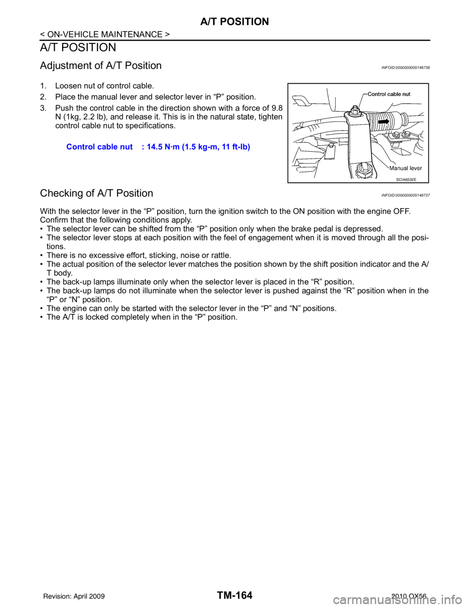
Adjustment of A/T PositionINFOID:0000000005148736
1. Loosen nut of control cable.
2. Place the manual lever and selector lever in “P” position.
3. Push the control cable in the direction shown with a force of 9.8
N (1kg, 2.2 lb), and release it. This is in the natural state, tighten
control cable nut to specifications.
Checking of A/T PositionINFOID:0000000005148737
With the selector lever in the “P” position, turn t he ignition switch to the ON position with the engine OFF.
Confirm that the following conditions apply.
• The selector lever can be shifted from the “P” position only when the brake pedal is depressed.
• The selector lever stops at each position with the f eel of engagement when it is moved through all the posi-
tions.
• There is no excessive effort, sticking, noise or rattle.
• The actual position of the selector lever matches the position shown by the shift position indicator and the A/
T body.
• The back-up lamps illuminate only when the selector lever is placed in the “R” position.
• The back-up lamps do not illuminate when the selector lever is pushed against the “R” position when in the “P” or “N” position.
• The engine can only be started with the select or lever in the “P” and “N” positions.
• The A/T is locked completely when in the “P” position. Control cable nut : 14.5 N·m (1.5 kg-m, 11 ft-lb)
SCIA6532E
Revision: April 20092010 QX56
Page 3873 of 4210
TM-178
< ON-VEHICLE REPAIR >
CONTROL VALVE WITH TCM
i. Install new O-ring (1) in plug (2).CAUTION:
• Do not reuse O-ring.
• Apply ATF to O-ring.
• O-ring should be free of contamination.
ii. Install plug (2) to bracket (1).
iii. Install plug (1) [with bracket (2)] to control valve with TCM. Tighten plug bolt ( ) to the specified torque.
CAUTION:
Adjust bolt hole of bracket to bolt hole of control valve with
TCM.
6. Install control valve with TCM in transmission case. CAUTION:
• Make sure that input speed sensor is securely installedinto input speed sensor hole (A).
• Hang down output speed sen sor harness toward outside
so as not to disturb installati on of control valve with TCM.
• Adjust A/T assembly harness co nnector of control valve
with TCM to terminal hole of transmission case.
• Assemble it so that manual valve cutout is engaged with manual plate projection.
JSDIA1313ZZ
JSDIA1312ZZ
JSDIA1311ZZ
1 : Brake band
JSDIA1318ZZ
SCIA5142E
Revision: April 20092010 QX56
Page 3888 of 4210
OVERHAULTM-193
< DISASSEMBLY AND ASSEMBLY >
CEF
G H
I
J
K L
M A
B
TM
N
O P
1. O-ring 2. Oil pump cover 3. O-ring
4. Oil pump housing 5. Self-sealing bolts 6. Torque converter
7. Converter housing 8. Oil pump housing oil seal 9. Bearing race
10. Needle bearing 11. O-ring 12. Front carrier assembly
13. Needle bearing 14. Snap ring 15. Front sun gear
16. 3rd one-way clutch 17. Snap ring 18. Bearing race
19. Needle bearing 20. Seal ring 21. Input clutch assembly
22. Needle bearing 23. Rear internal gear 24. Brake band
25. Mid carrier assembly 26. Needle bearing 27. Bearing race
28. Rear carrier assembly 29. Needle bearing 30. Mid sun gear
31. Seal ring 32. Rear sun gear 33. 1st one-way clutch
34. Snap ring 35. Needle bearing 36. High and low reverse clutch hub
37. Snap ring 38. Bearing race 39. Needle bearing
Revision: April 20092010 QX56
Page 3889 of 4210
TM-194
< DISASSEMBLY AND ASSEMBLY >
OVERHAUL
1. Needle bearing2. Bearing race3. High and low reverse clutch assembly
4. Needle bearing 5. Direct clutch assembly6. Reverse brake dish plate
7. Reverse brake dish plate 8. Reverse brake driven plate 9. N-spring
10. Reverse brake drive plate 11. Reverse brake retaining plate 12. Snap ring
13. D-ring 14. D-ring15. Reverse brake piston
16. Return spring 17. Spring retainer18. Snap ring
SCIA7001E
Revision: April 20092010 QX56
Page 3902 of 4210
DISASSEMBLYTM-207
< DISASSEMBLY AND ASSEMBLY >
CEF
G H
I
J
K L
M A
B
TM
N
O P
14. Loosen lock nut and remove band servo anchor end pin from transmission case.
15. Remove brake band from transmission case.
CAUTION:
• To prevent brake linings from cracking or peeling, do not
stretch the flexible band unnecessarily. When removing
the brake band, always secure it with a clip as shown.
• Check brake band facing for damage, cracks, wear or
burns.
16. Remove mid carrier assembly and rear carrier assembly as a unit.
SCIA6512E
SCIA2580E
SAT655
SCIA5017E
Revision: April 20092010 QX56
Page 3904 of 4210
DISASSEMBLYTM-209
< DISASSEMBLY AND ASSEMBLY >
CEF
G H
I
J
K L
M A
B
TM
N
O P
22. Remove mid sun gear assembly , rear sun gear assembly and
high and low reverse clutch hub as a unit.
CAUTION:
Remove them with bearing race and needle bearing.
23. Remove high and low reverse clutch assembly from direct clutch assembly.
CAUTION:
Make sure that needle bearing is installed to the high and
low reverse clutch assembly edge surface.
24. Remove needle bearing from drum support.
25. Remove direct clutch assembly from reverse brake.
26. Remove snap ring from A/T assembly harness connector.
SCIA5018E
SCIA2306E
SCIA5198E
SCIA5019E
SCIA5021E
Revision: April 20092010 QX56
Page 3912 of 4210

DISASSEMBLYTM-217
< DISASSEMBLY AND ASSEMBLY >
CEF
G H
I
J
K L
M A
B
TM
N
O P
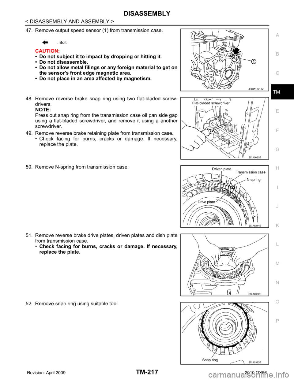
47. Remove output speed sensor (1) from transmission case.
CAUTION:
• Do not subject it to impact by dropping or hitting it.
• Do not disassemble.
• Do not allow metal filings or any foreign material to get onthe sensor's front edge magnetic area.
• Do not place in an area affected by magnetism.
48. Remove reverse brake snap ring using two flat-bladed screw- drivers.
NOTE:
Press out snap ring from the transmission case oil pan side gap
using a flat-bladed screwdriver, and remove it using a another
screwdriver.
49. Remove reverse brake retaining plate from transmission case. • Check facing for burns, cracks or damage. If necessary,
replace the plate.
50. Remove N-spring from transmission case.
51. Remove reverse brake drive plates, driven plates and dish plate from transmission case.
•Check facing for burns, cracks or damage. If necessary,
replace the plate.
52. Remove snap ring using suitable tool.
: Bolt
JSDIA1321ZZ
SCIA5032E
SCIA5214E
SCIA2322E
SCIA2323E
Revision: April 20092010 QX56