2010 INFINITI QX56 wiring diagram
[x] Cancel search: wiring diagramPage 2470 of 4210

INL-1
DRIVER CONTROLS
C
DE
F
G H
I
J
K
M
SECTION INL
A
B
INL
N
O P
CONTENTS
INTERIOR LIGHTING SYSTEM
BASIC INSPECTION ....... .............................3
DIAGNOSIS AND REPAIR WORKFLOW ..... .....3
Work Flow ........................................................... ......3
FUNCTION DIAGNOSIS ...............................6
INTERIOR ROOM LAMP CONTROL SYSTEM
.....
6
System Diagram .................................................. ......6
System Description ...................................................6
Component Parts Location ........................................7
Component Description .............................................8
ILLUMINATION CONTROL SYSTEM .................9
System Diagram .................................................. ......9
System Description ...................................................9
Component Parts Location ........................................9
Component Description ...........................................10
DIAGNOSIS SYSTEM (BCM) ............................11
COMMON ITEM ..................................................... ....11
COMMON ITEM : CONSULT-III Function (BCM -
COMMON ITEM) .....................................................
11
INT LAMP .............................................................. ....11
INT LAMP : CONSULT-III Function (BCM - INT
LAMP) .....................................................................
12
BATTERY SAVER ................................................. ....13
BATTERY SAVER : CONSULT-III Function (BCM
- BATTERY SAVER) ...............................................
13
COMPONENT DIAGNOSIS .........................15
POWER SUPPLY AND GROUND CIRCUIT .. ....15
BCM ....................................................................... ....15
BCM : Diagnosis Procedure ....................................15
BATTERY SAVER OUTPUT/POWER SUP-
PLY CIRCUIT ................................................. ....
17
Description ........................................................... ....17
Component Function Check ....................................17
Diagnosis Procedure ...............................................17
INTERIOR ROOM LAMP CONTROL CIRCUIT
...
19
Description ........................................................... ....19
Component Function Check ....................................19
Diagnosis Procedure ...............................................19
STEP LAMP CIRCUIT .......................................22
Description ........................................................... ....22
Component Function Check ....................................22
Diagnosis Procedure ...............................................22
CARGO LAMP CONTROL CIRCUIT ................24
Description ...............................................................24
Component Function Check ....................................24
Diagnosis Procedure ...............................................24
IGNITION KEYHOLE ILLUMINATION CON-
TROL CIRCUIT .................................................
26
Description ...............................................................26
Component Function Check ....................................26
Diagnosis Procedure ...............................................26
INTERIOR ROOM LAMP CONTROL SYSTEM
...
28
Wiring Diagram .................................................... ....28
ILLUMINATION .................................................44
Wiring Diagram ........................................................44
ECU DIAGNOSIS .........................................58
BCM (BODY CONTROL MODULE) .................58
Reference Value .................................................. ....58
Terminal Layout .......................................................61
Physical Values ................................................... ....61
Wiring Diagram ........................................................67
Fail Safe ..................................................................71
DTC Inspection Priority Chart ...............................72
Revision: April 20092010 QX56
Page 2484 of 4210
POWER SUPPLY AND GROUND CIRCUITINL-15
< COMPONENT DIAGNOSIS >
C
DE
F
G H
I
J
K
M A
B
INL
N
O P
COMPONENT DIAGNOSIS
POWER SUPPLY AND GROUND CIRCUIT
BCM
BCM : Diagnosis ProcedureINFOID:0000000005356487
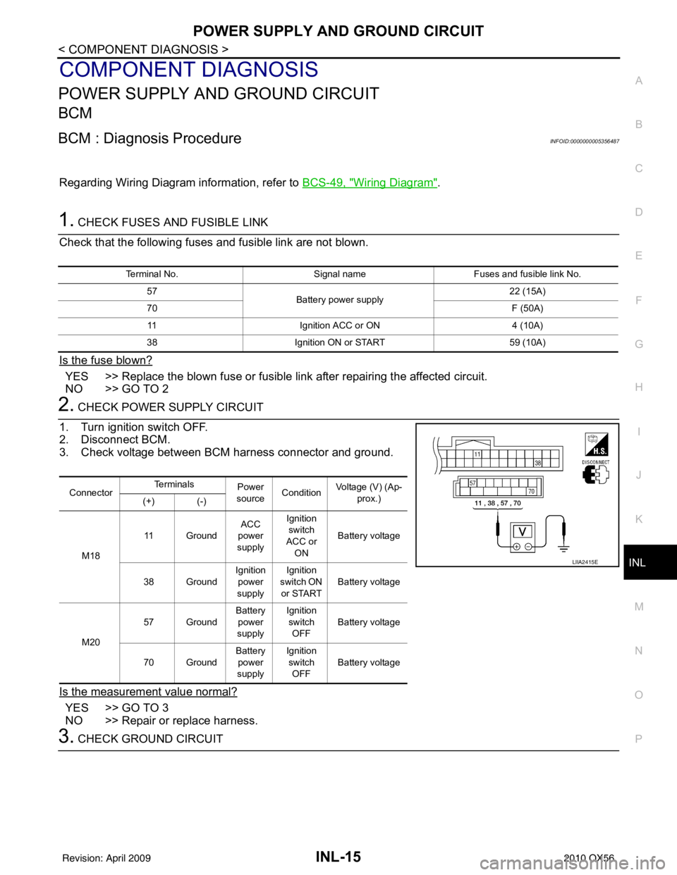
Regarding Wiring Diagram information, refer to BCS-49, "Wiring Diagram".
1. CHECK FUSES AND FUSIBLE LINK
Check that the following fuses and fusible link are not blown.
Is the fuse blown?
YES >> Replace the blown fuse or fusible link after repairing the affected circuit.
NO >> GO TO 2
2. CHECK POWER SUPPLY CIRCUIT
1. Turn ignition switch OFF.
2. Disconnect BCM.
3. Check voltage between BCM harness connector and ground.
Is the measurement value normal?
YES >> GO TO 3
NO >> Repair or replace harness.
3. CHECK GROUND CIRCUIT
Terminal No. Signal nameFuses and fusible link No.
57 Battery power supply 22 (15A)
70 F (50A)
11 Ignition ACC or ON 4 (10A)
38 Ignition ON or START 59 (10A)
ConnectorTe r m i n a l s
Power
source Condition Voltage (V) (Ap-
prox.)
(+) (-)
M18 11 Ground
ACC
power
supply Ignition
switch
ACC or ON Battery voltage
38 Ground Ignition
power
supply Ignition
switch ON
or START Battery voltage
M20 57 Ground
Battery
power
supply Ignition
switch OFF Battery voltage
70 Ground Battery
power
supply Ignition
switch OFF Battery voltage
LIIA2415E
Revision: April 20092010 QX56
Page 2486 of 4210
BATTERY SAVER OUTPUT/POWER SUPPLY CIRCUITINL-17
< COMPONENT DIAGNOSIS >
C
DE
F
G H
I
J
K
M A
B
INL
N
O P
BATTERY SAVER OUTPUT/POWER SUPPLY CIRCUIT
DescriptionINFOID:0000000005146727
Provides the battery saver output/power supply. Also cu ts the power supply when the interior room lamp bat-
tery saver is activating.
Component Function CheckINFOID:0000000005146728
1.CHECK BATTERY SAVER OUTPUT /POWER SUPPLY FUNCTION
CONSULT-III
1. Turn ignition switch ON.
2. Turn each interior room lamp ON.
- Front room/map lamp assembly
- Vanity lamps
- Personal lamp 2nd row
- Personal lamp 3rd row
- Cargo lamp
3. Open the driver door to turn ON the step lamps, foot lamps and puddle lamps.
- Front step lamps
- Rear step lamps
- Foot lamps
- Puddle lamps
- Ignition keyhole Illumination
4. Select “BATTERY SAVER” of BCM (BATTERY SAVER) active test item.
5. While operating the test item, check that each interior room lamp turns ON/OFF.
Is the inspection result normal?
YES >> Battery saver output/power supply circuit is normal.
NO >> Refer to INL-17, "
Diagnosis Procedure".
Diagnosis ProcedureINFOID:0000000005146729
Regarding Wiring Diagram information, refer to BCS-49, "Wiring Diagram".
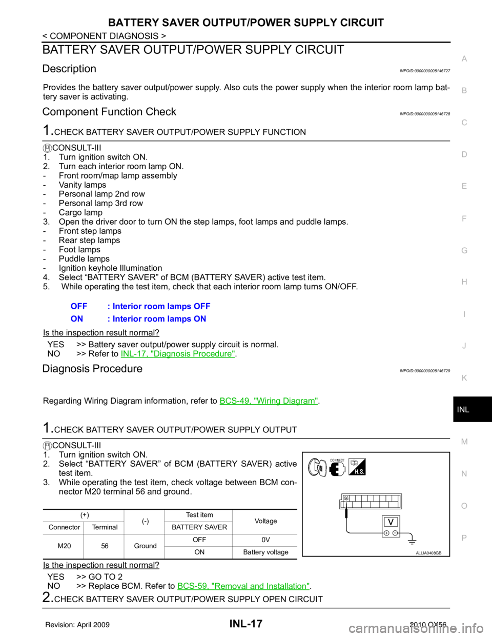
1.CHECK BATTERY SAVER OUTPUT/POWER SUPPLY OUTPUT
CONSULT-III
1. Turn ignition switch ON.
2. Select “BATTERY SAVER” of BCM (BATTERY SAVER) active
test item.
3. While operating the test item, check voltage between BCM con-
nector M20 terminal 56 and ground.
Is the inspection result normal?
YES >> GO TO 2
NO >> Replace BCM. Refer to BCS-59, "
Removal and Installation".
2.CHECK BATTERY SAVER OUTPUT/P OWER SUPPLY OPEN CIRCUIT
OFF : Interior room lamps OFF
ON : Interior room lamps ON
(+)
(-)Te s t i t e m
Voltag e
Connector Terminal BATTERY SAVER
M20 56 Ground OFF
0V
ON Battery voltage
ALLIA0408GB
Revision: April 20092010 QX56
Page 2488 of 4210
INTERIOR ROOM LAMP CONTROL CIRCUITINL-19
< COMPONENT DIAGNOSIS >
C
DE
F
G H
I
J
K
M A
B
INL
N
O P
INTERIOR ROOM LAMP CONTROL CIRCUIT
DescriptionINFOID:0000000005146730
Controls the following interior room lamps (ground side) by PWM signal
• Puddle lamps
• Front room/map lamp assembly
• Personal lamp 2nd row
• Personal lamp 3rd row
NOTE:
PWM signal control period is approximately 250 Hz (in the gradual brightening/dimming).
Component Function CheckINFOID:0000000005146731
CAUTION:
Before performing the diagnosis, check that the following is normal.
• Battery saver output/power supply
• Front room/map lamp bulbs
• Personal lamp bulbs
• Puddle lamp bulbs
1.CHECK INTERIOR ROOM LAMP CONTROL FUNCTION
CONSULT-III
1. Switch the front room/map lamp assembly switch to DOOR.
2. Turn ignition switch ON.
3. Select “INT LAMP” of BCM (INT LAMP) active test item.
4. While operating the test item, check that each interi or room lamp turns ON/OFF (gradual brightening/dim-
ming).
Is the inspection result normal?
YES >> Interior room lamp control circuit is normal.
NO >> Refer to INL-19, "
Diagnosis Procedure".
Diagnosis ProcedureINFOID:0000000005146732
Regarding Wiring Diagram information, refer to INL-28, "Wiring Diagram".
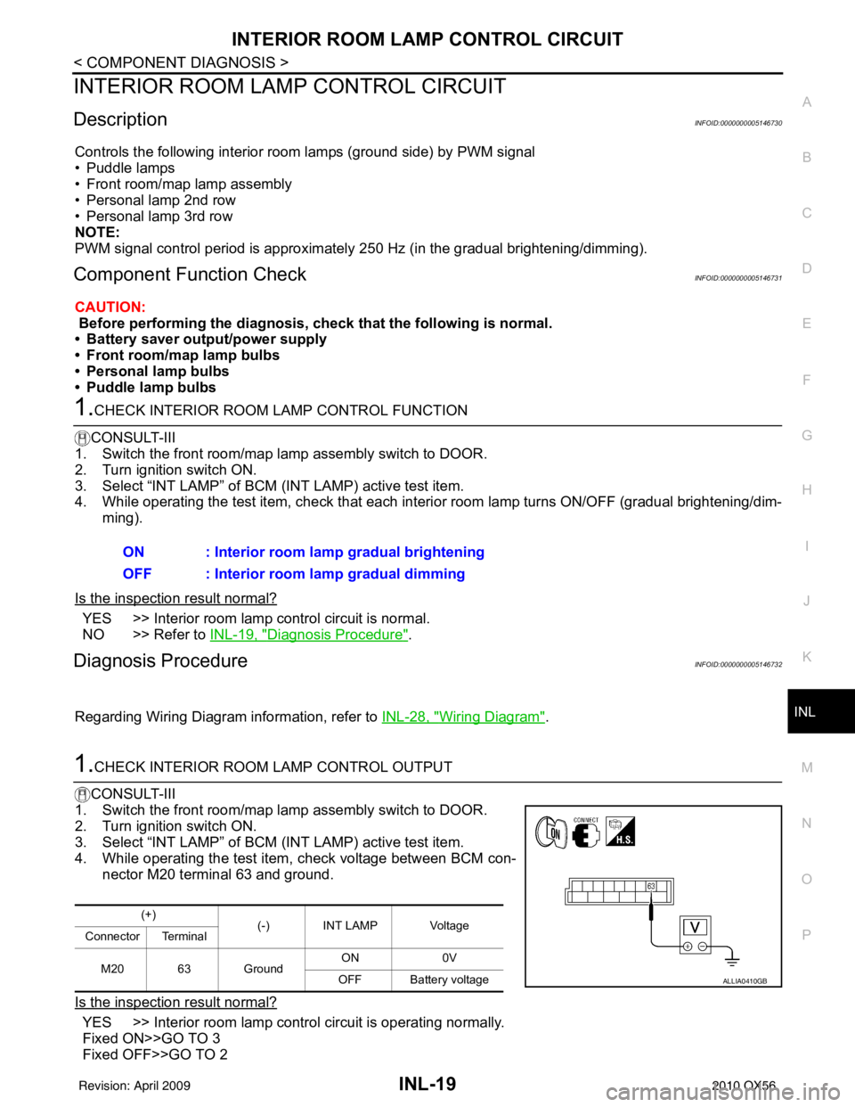
1.CHECK INTERIOR ROOM LAMP CONTROL OUTPUT
CONSULT-III
1. Switch the front room/map lamp assembly switch to DOOR.
2. Turn ignition switch ON.
3. Select “INT LAMP” of BCM (INT LAMP) active test item.
4. While operating the test item, check voltage between BCM con- nector M20 terminal 63 and ground.
Is the inspection result normal?
YES >> Interior room lamp control circuit is operating normally.
Fixed ON>>GO TO 3
Fixed OFF>>GO TO 2 ON : Interior room lamp gradual brightening
OFF : Interior room lamp gradual dimming
(+)
(-) INT LAMP Voltage
Connector Terminal
M20 63 Ground ON
0V
OFF Battery voltage
ALLIA0410GB
Revision: April 20092010 QX56
Page 2491 of 4210
INL-22
< COMPONENT DIAGNOSIS >
STEP LAMP CIRCUIT
STEP LAMP CIRCUIT
DescriptionINFOID:0000000005146733
Controls the front and rear step lamps and the foot lamps (ground side) to turn the lamps ON and OFF.
Component Function CheckINFOID:0000000005146734
CAUTION:
Before performing the diagnosis, check that the following is normal.
• Battery saver output/power supply
• Front step lamp bulbs
• Rear step lamp bulbs
• Foot lamp bulbs
1.CHECK STEP LAMP OPERATION
CONSULT-III
1. Turn ignition switch ON.
2. Select “STEP LAMP TEST” of BCM (INT LAMP) active test item.
3. While operating the test item, check that the front/rear step lamps and foot lamps turn ON/OFF.
Is the inspection result normal?
YES >> Step lamp circuit is normal.
NO >> Refer to INL-22, "
Diagnosis Procedure".
Diagnosis ProcedureINFOID:0000000005146735
Regarding Wiring Diagram information, refer to INL-28, "Wiring Diagram".
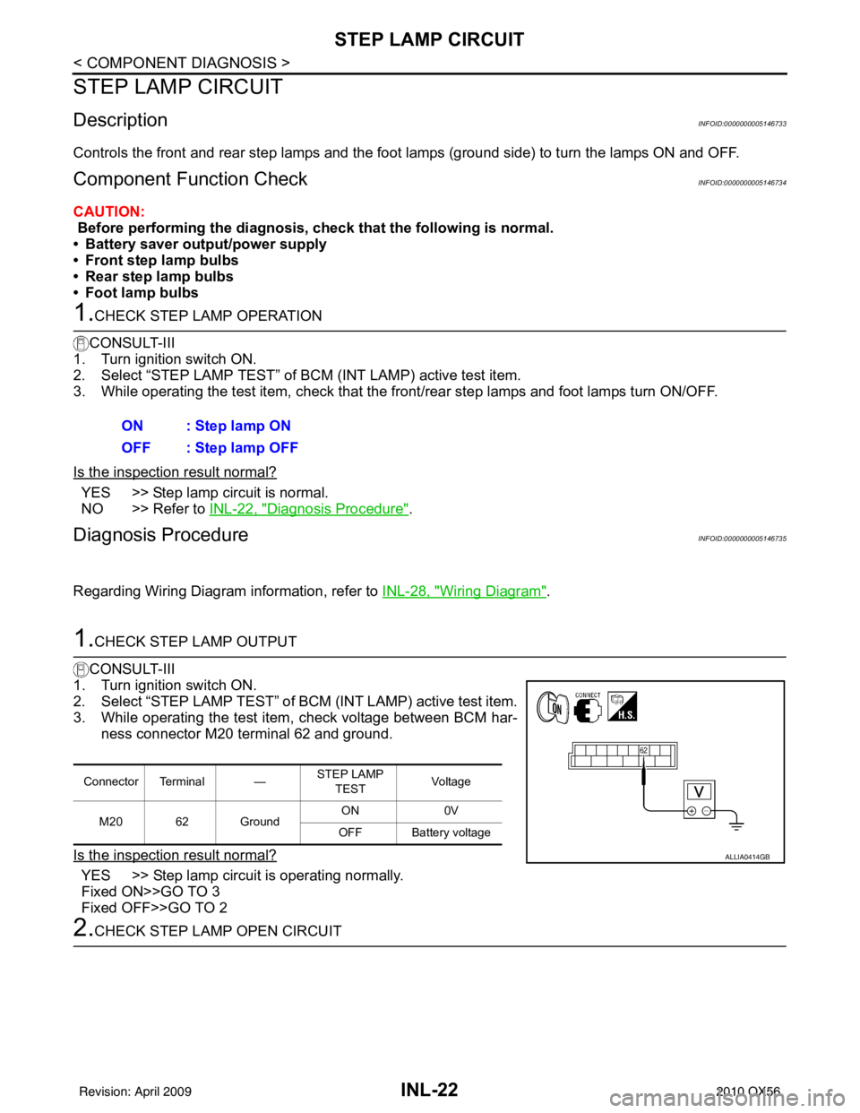
1.CHECK STEP LAMP OUTPUT
CONSULT-III
1. Turn ignition switch ON.
2. Select “STEP LAMP TEST” of BCM (INT LAMP) active test item.
3. While operating the test item, check voltage between BCM har- ness connector M20 terminal 62 and ground.
Is the inspection result normal?
YES >> Step lamp circuit is operating normally.
Fixed ON>>GO TO 3
Fixed OFF>>GO TO 2
2.CHECK STEP LAMP OPEN CIRCUIT ON : Step lamp ON
OFF : Step lamp OFF
Connector Terminal —
STEP LAMP
TEST Voltag e
M20 62 Ground ON
0V
OFF Battery voltage
ALLIA0414GB
Revision: April 20092010 QX56
Page 2493 of 4210
INL-24
< COMPONENT DIAGNOSIS >
CARGO LAMP CONTROL CIRCUIT
CARGO LAMP CONTROL CIRCUIT
DescriptionINFOID:0000000005146736
Controls the cargo lamp (ground side) to turn the cargo lamp ON and OFF.
Component Function CheckINFOID:0000000005146737
CAUTION:
Before performing the diagnosis, check that the following is normal.
• Battery saver output/power supply
• Cargo lamp bulb
1.CHECK CARGO LAMP OPERATION
CONSULT-III
1. Turn ignition switch ON.
2. Select “LUGGAGE LAMP TEST” of BCM (INT LAMP) active test item.
3. While operating the test item, che ck that cargo lamp turns ON/OFF.
Is the inspection result normal?
YES >> Cargo lamp circuit is normal.
NO >> Refer to INL-22, "
Diagnosis Procedure".
Diagnosis ProcedureINFOID:0000000005146738
Regarding Wiring Diagram information, refer to INL-28, "Wiring Diagram".
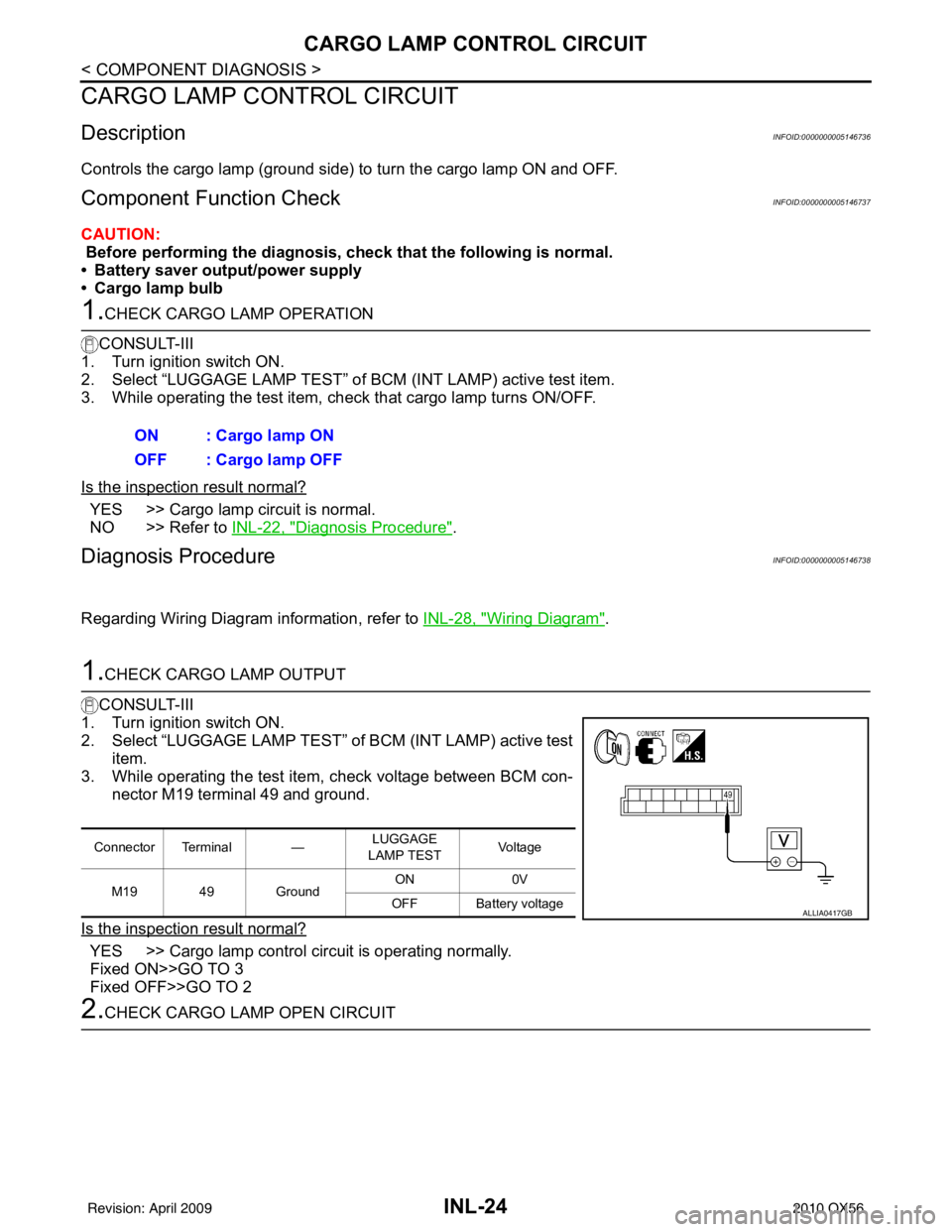
1.CHECK CARGO LAMP OUTPUT
CONSULT-III
1. Turn ignition switch ON.
2. Select “LUGGAGE LAMP TEST” of BCM (INT LAMP) active test
item.
3. While operating the test item, check voltage between BCM con-
nector M19 terminal 49 and ground.
Is the inspection result normal?
YES >> Cargo lamp control circuit is operating normally.
Fixed ON>>GO TO 3
Fixed OFF>>GO TO 2
2.CHECK CARGO LAMP OPEN CIRCUIT ON : Cargo lamp ON
OFF : Cargo lamp OFF
Connector Terminal —
LUGGAGE
LAMP TEST Voltag e
M19 49 Ground ON
0V
OFF Battery voltage
ALLIA0417GB
Revision: April 20092010 QX56
Page 2495 of 4210
INL-26
< COMPONENT DIAGNOSIS >
IGNITION KEYHOLE ILLUMINATION CONTROL CIRCUIT
IGNITION KEYHOLE ILLUMINATION CONTROL CIRCUIT
DescriptionINFOID:0000000005146739
Controls the ignition keyhole illumination (ground side) to turn the ignition keyhole illumination ON and OFF.
Component Function CheckINFOID:0000000005146740
CAUTION:
Before performing the diagnosis, check that the following is normal.
• Battery saver output/power supply circuit
• Ignition keyhole illumination bulb
1.CHECK IGNITION KEYHOLE ILLUMINATION OPERATION
CONSULT-III
1. Turn the ignition switch ON.
2. Select “IGN ILLUM” of BCM (INT LAMP) active test item.
3. While operating the test item , check that the ignition keyhole illumination turns ON/OFF
Is the inspection result normal?
YES >> Ignition keyhole illumination circuit is normal.
NO >> Refer to INL-26, "
Diagnosis Procedure".
Diagnosis ProcedureINFOID:0000000005146741
Regarding Wiring Diagram information, refer to INL-28, "Wiring Diagram".
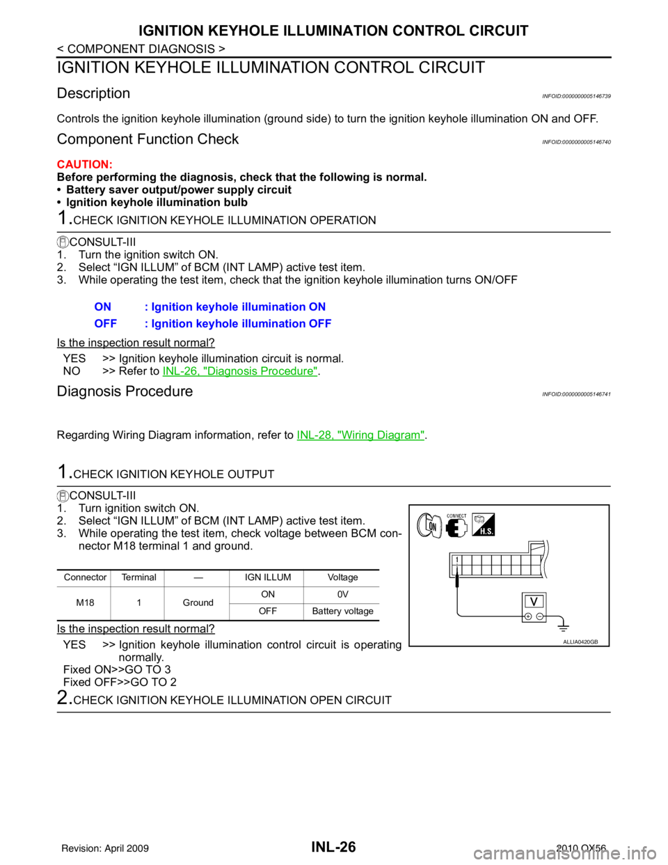
1.CHECK IGNITION KEYHOLE OUTPUT
CONSULT-III
1. Turn ignition switch ON.
2. Select “IGN ILLUM” of BCM (INT LAMP) active test item.
3. While operating the test item, check voltage between BCM con- nector M18 terminal 1 and ground.
Is the inspection result normal?
YES >> Ignition keyhole illumination control circuit is operating normally.
Fixed ON>>GO TO 3
Fixed OFF>>GO TO 2
2.CHECK IGNITION KEYHOLE ILLUMINATION OPEN CIRCUIT ON : Ignition keyhole illumination ON
OFF : Ignition keyhole illumination OFF
Connector Terminal — IGN ILLUM Voltage
M18 1 Ground ON
0V
OFF Battery voltage
ALLIA0420GB
Revision: April 20092010 QX56
Page 2497 of 4210
INL-28
< COMPONENT DIAGNOSIS >
INTERIOR ROOM LAMP CONTROL SYSTEM
INTERIOR ROOM LAMP CONTROL SYSTEM
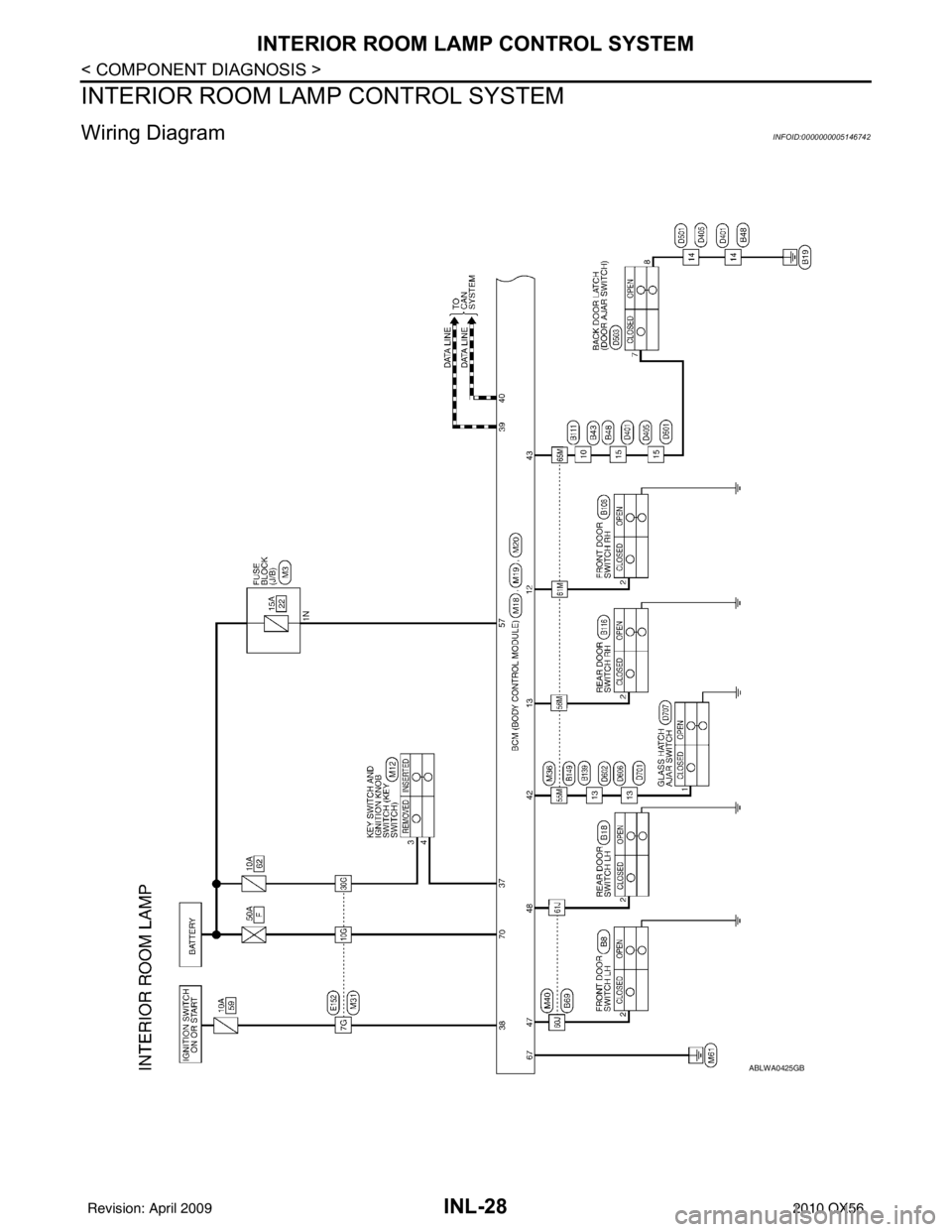
Wiring DiagramINFOID:0000000005146742
ABLWA0425GB
Revision: April 20092010 QX56