2010 INFINITI QX56 wheel bolts
[x] Cancel search: wheel boltsPage 2216 of 4210
LOWER LINKFSU-17
< REMOVAL AND INSTALLATION >
C
DF
G H
I
J
K L
M A
B
FSU
N
O P
LOWER LINK
Removal and InstallationINFOID:0000000005148116
REMOVAL
1. Remove the wheel and tire using power tool.
2. Remove lower shock absorber bolt.
3. Remove stabilizer bar connecting rod lower nut using power tool, then separate connecting rod from lower
link. Refer to FSU-15, "
Removal and Installation" .
4. Remove drive shaft nut, if equipped. Refer to FA X - 9 , "
Removal and Installation" .
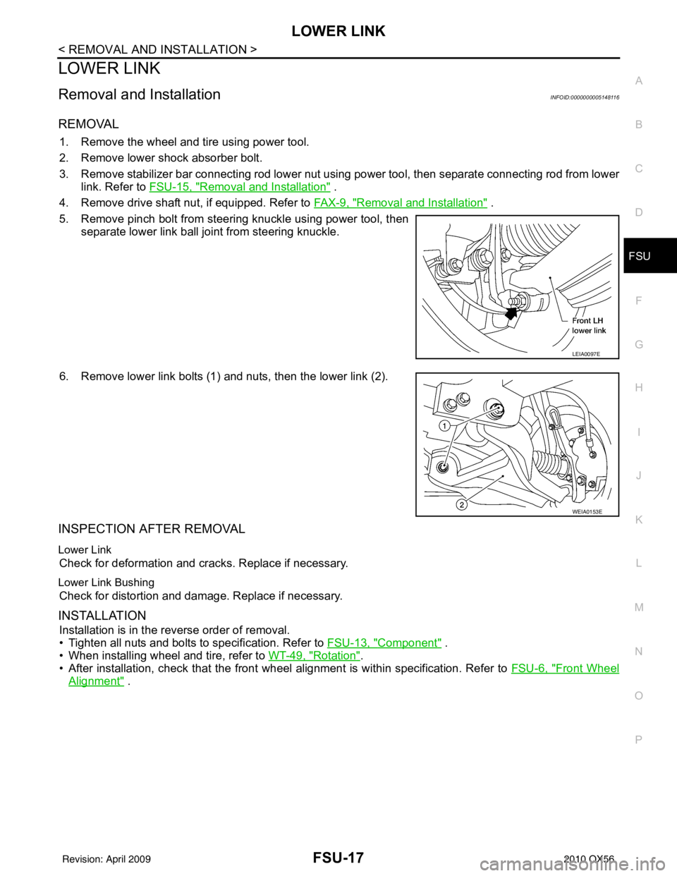
5. Remove pinch bolt from steering knuckle using power tool, then separate lower link ball joint from steering knuckle.
6. Remove lower link bolts (1) and nuts, then the lower link (2).
INSPECTION AFTER REMOVAL
Lower Link
Check for deformation and cracks. Replace if necessary.
Lower Link Bushing
Check for distortion and damage. Replace if necessary.
INSTALLATION
Installation is in the reverse order of removal.
• Tighten all nuts and bolts to specification. Refer to FSU-13, "
Component" .
• When installing wheel and tire, refer to WT-49, "
Rotation".
• After installation, check that the front wheel alignment is within specification. Refer to FSU-6, "
Front Wheel
Alignment" .
LEIA0097E
WEIA0153E
Revision: April 20092010 QX56
Page 2224 of 4210
GI-1
GENERAL INFORMATION
C
DE
F
G H
I
J
K L
M B
GI
SECTION GI
N
O P
CONTENTS
GENERAL INFORMATION
HOW TO USE THIS MANU AL ......................3
HOW TO USE THIS MANUAL ....................... .....3
Description .......................................................... ......3
Terms ........................................................................3
Units ..........................................................................3
Contents ....................................................................3
Relation between Illustrations and Descriptions .......4
Components ..............................................................4
HOW TO FOLLOW TROUBLE DIAGNOSES .....6
Description ................................................................6
How to Follow Test Groups in Trouble Diagnosis ......6
Key to Symbols Signifying Measurements or Pro-
cedures ............................................................... ......
7
HOW TO READ WIRING DIAGRAMS ................9
Connector symbols ............................................. ......9
Sample/wiring diagram -example- ...........................10
Description ..............................................................11
ABBREVIATIONS .......................................... ....13
Abbreviation List .................................................. ....13
TIGHTENING TORQUE OF STANDARD
BOLTS ................................................................
14
Tightening Torque Table .........................................14
RECOMMENDED CHEMICAL PRODUCTS
AND SEALANTS ............................................ ....
15
Recommended Chemical Products and Sealants ....15
TERMINOLOGY .................................................16
SAE J1930 Terminology List ............................... ....16
FEATURES OF NEW MODEL .....................20
IDENTIFICATION INFORMATION .....................20
Model Variation ................................................... ....20
Identification Number ..............................................21
Identification Plate ...................................................22
Dimensions .............................................................23
Wheels & Tires .................................................... ....23
PRECAUTION ..............................................24
PRECAUTIONS .................................................24
Description ........................................................... ....24
Precaution for Supplemental Restraint System
(SRS) "AIR BAG" and "SEAT BELT PRE-TEN-
SIONER" .................................................................
24
Precaution Necessary for Steering Wheel Rota-
tion After Battery Disconnect ...................................
24
Procedures without Cowl Top Cover .......................25
General Precautions ................................................25
Three Way Catalyst .................................................27
Precaution for Fuel (Unleaded Premium Gasoline
Required) .................................................................
27
Multiport Fuel Injection System or Engine Control
System .....................................................................
27
Hoses ......................................................................27
Engine Oils ..............................................................28
Air Conditioning .......................................................29
LIFTING POINT .................................................30
Pantograph Jack ......................................................30
Garage Jack and Safety Stand ................................30
2-Pole Lift ................................................................30
TOW TRUCK TOWING .....................................32
Tow Truck Towing ...................................................32
Vehicle Recovery (Freeing a stuck vehicle) ............33
BASIC INSPECTION ...................................34
SERVICE INFORMATION FOR ELECTRICAL
INCIDENT ..........................................................
34
Work Flow ............................................................ ....34
Control Units and Electrical Parts ............................34
How to Check Terminal ...........................................35
Intermittent Incident ............................................. ....38
Circuit Inspection .....................................................41
CONSULT-III CHECKING SYSTEM .................46
Revision: April 20092010 QX56
Page 2323 of 4210
COMPRESSORHA-31
< ON-VEHICLE REPAIR >
C
DE
F
G H
J
K L
M A
B
HA
N
O P
COMPRESSOR
Removal and Installation for CompressorINFOID:0000000005147653
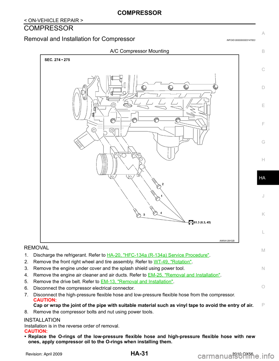
A/C Compressor Mounting
REMOVAL
1. Discharge the refrigerant. Refer to HA-20, "HFC-134a (R-134a) Service Procedure".
2. Remove the front right wheel and tire assembly. Refer to WT-49, "
Rotation".
3. Remove the engine under cover and the splash shield using power tool.
4. Remove the engine air cleaner and air ducts. Refer to EM-25, "
Removal and Installation".
5. Remove the drive belt. Refer to EM-13, "
Removal and Installation".
6. Disconnect the compressor electrical connector.
7. Disconnect the high-pressure flexible hose and low-pressure flexible hose from the compressor. CAUTION:
Cap or wrap the joint of the pipe with suitable mate rial such as vinyl tape to avoid the entry of air.
8. Remove the compressor bolts and nut using power tools.
INSTALLATION
Installation is in the reverse order of removal.
CAUTION:
• Replace the O-rings of the low-pressure flexibl e hose and high-pressure flexible hose with new
ones, apply compressor oil to th e O-rings when installing them.
AWIIA1291GB
Revision: April 20092010 QX56
Page 2331 of 4210
LOW-PRESSURE PIPEHA-39
< ON-VEHICLE REPAIR >
C
DE
F
G H
J
K L
M A
B
HA
N
O P
5. Remove the front and rear bumper fascia. Refer to EXT-13, "Removal and Installation" (front), EXT-15,
"Removal and Installation" (rear).
6. Reposition the front fender protector out of the way. Refer to EXT-23, "
Removal and Installation".
7. Disconnect the chassis harness connector.
8. Remove the spare wheel and tire.
9. Remove the tailpipe and tailpipe hanger bracket. Refer to EX-6, "
Removal and Installation".
10. Remove the seatbelt latch anchor. Refer to EX-6, "
Removal and Installation".
11. Remove the front floor heat shield.
12. Disconnect each end of the underfloor rear high- and low-pressure A/C and heater core pipes. Refer to HA-29, "
Component".
CAUTION:
Cap or wrap the joint of the pipes with suitable material such as viny l tape to avoid the entry of air.
13. Set two suitable jacks at the RH body mount points to support the vehicle body when it is separated from the RH side of the frame.
14. Remove the RH body mount bolts. Refer to BRM-6, "
Body Mounting".
15. Use the vehicle hoist to lower the RH side of the frame from the RH side of the body [approximately 305 mm (12 in)] until there is sufficient clearance to remove the underfloor rear high- and low-pressure A/C
and heater core pipes from between the body and the frame.
16. Remove the underfloor rear high- and low-pressure A/C and heater core pipes from the back of the vehi- cle.
INSTALLATION
Installation is in the reverse order of removal.
CAUTION:
• Replace the O-rings of the underfloor rear high - and low-pressure A/C and heater core pipes with
new ones, then apply compressor oil to them for installation.
• After charging refrigerant, check for leaks.
Revision: April 20092010 QX56
Page 2335 of 4210
HIGH-PRESSURE PIPEHA-43
< ON-VEHICLE REPAIR >
C
DE
F
G H
J
K L
M A
B
HA
N
O P
5. Remove the front and rear bumper fascia. Refer to EXT-13, "Removal and Installation" (front), EXT-15,
"Removal and Installation" (rear).
6. Reposition the front fender protector out of the way. Refer to EXT-23, "
Removal and Installation".
7. Disconnect the chassis harness connector.
8. Remove the spare wheel and tire.
9. Remove the tailpipe and tailpipe hanger bracket. Refer to EX-6, "
Removal and Installation".
10. Remove the seatbelt latch anchor. Refer to EX-6, "
Removal and Installation".
11. Remove the front floor heat shield.
12. Disconnect each end of the underfloor rear high- and low-pressure A/C and heater core pipes. Refer to HA-29, "
Component".
CAUTION:
Cap or wrap the joint of the pipes with suitable material such as viny l tape to avoid the entry of air.
13. Set two suitable jacks at the RH body mount points to support the vehicle body when it is separated from the RH side of the frame.
14. Remove the RH body mount bolts. Refer to BRM-6, "
Body Mounting".
15. Use the vehicle hoist to lower the RH side of the frame from the RH side of the body [approximately 305 mm (12 in)] until there is sufficient clearance to remove the underfloor rear high- and low-pressure A/C
and heater core pipes from between the body and the frame.
16. Remove the underfloor rear high- and low-pressure A/C and heater core pipes from the back of the vehi- cle.
INSTALLATION
Installation is in the reverse order of removal.
CAUTION:
• Replace the O-rings of the underfloor rear high - and low-pressure A/C and heater core pipes with
new ones, then apply compressor oil to them for installation.
• After charging refrigerant, check for leaks.
Revision: April 20092010 QX56
Page 2742 of 4210
MA-38
< ON-VEHICLE MAINTENANCE >
CHASSIS AND BODY MAINTENANCE
• Shake each wheel to check for excessive play.
• Rotate each wheel to check for abnormal noise.
• Check the axle and suspension nuts and bolts for looseness.
• Check the strut and shock absorber for oil leakage or other damage.
• Check the suspension ball joints for grease leakage and ball joint dust cover for cracks or other damage.
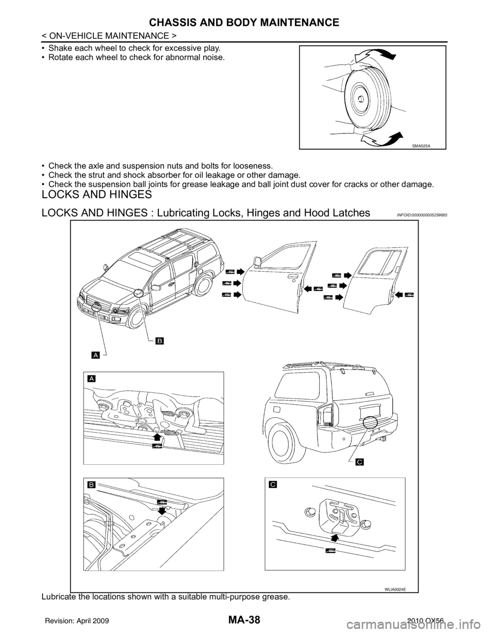
LOCKS AND HINGES
LOCKS AND HINGES : Lubricating Locks, Hinges and Hood LatchesINFOID:0000000005259685
Lubricate the locations shown with a suitable multi-purpose grease.
SMA525A
WLIA0024E
Revision: April 20092010 QX56
Page 3120 of 4210
RAX-8
< REMOVAL AND INSTALLATION >
WHEEL HUB
REMOVAL AND INSTALLATION
WHEEL HUB
Removal and InstallationINFOID:0000000005148956
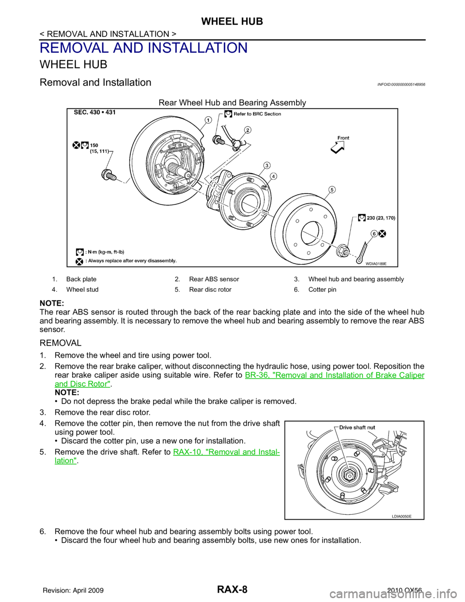
Rear Wheel Hub and Bearing Assembly
NOTE:
The rear ABS sensor is routed through the back of the rear backing plate and into the side of the wheel hub
and bearing assembly. It is necessary to remove the wheel hub and bearing assembly to remove the rear ABS
sensor.
REMOVAL
1. Remove the wheel and tire using power tool.
2. Remove the rear brake caliper, without disconnecting the hydraulic hose, using power tool. Reposition the
rear brake caliper aside using suitable wire. Refer to BR-36, "
Removal and Installation of Brake Caliper
and Disc Rotor".
NOTE:
• Do not depress the brake pedal while the brake caliper is removed.
3. Remove the rear disc rotor.
4. Remove the cotter pin, then remove the nut from the drive shaft using power tool.
• Discard the cotter pin, use a new one for installation.
5. Remove the drive shaft. Refer to RAX-10, "
Removal and Instal-
lation".
6. Remove the four wheel hub and bearing assembly bolts using power tool. • Discard the four wheel hub and bearing assembly bolts, use new ones for installation.
WDIA0189E
1. Back plate 2. Rear ABS sensor3. Wheel hub and be aring assembly
4. Wheel stud 5. Rear disc rotor6. Cotter pin
LDIA0050E
Revision: April 20092010 QX56
Page 3121 of 4210
WHEEL HUBRAX-9
< REMOVAL AND INSTALLATION >
CEF
G H
I
J
K L
M A
B
RAX
N
O P
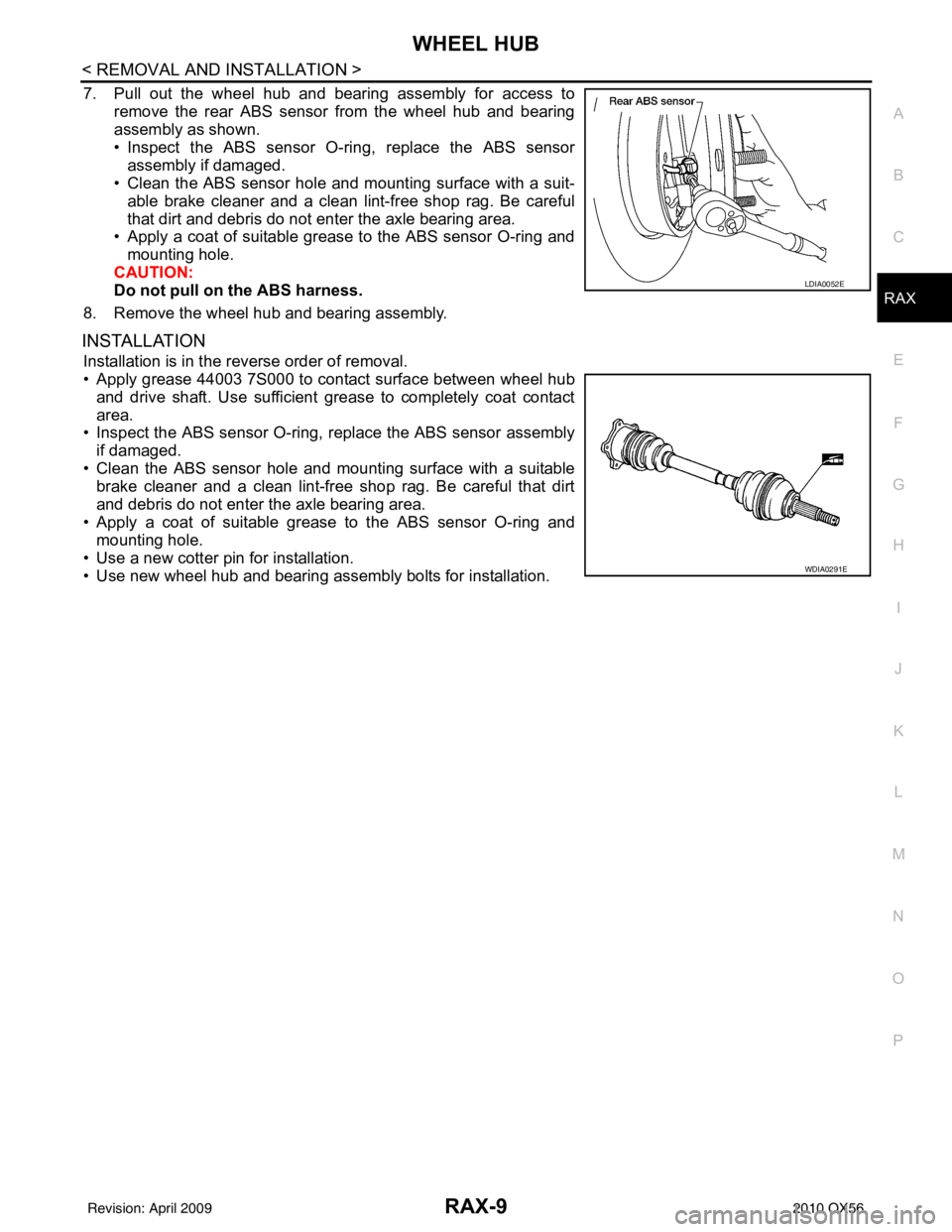
7. Pull out the wheel hub and bearing assembly for access to remove the rear ABS sensor from the wheel hub and bearing
assembly as shown.
• Inspect the ABS sensor O-ri ng, replace the ABS sensor
assembly if damaged.
• Clean the ABS sensor hole and mounting surface with a suit-
able brake cleaner and a clean lint-free shop rag. Be careful
that dirt and debris do not enter the axle bearing area.
• Apply a coat of suitable grease to the ABS sensor O-ring and
mounting hole.
CAUTION:
Do not pull on the ABS harness.
8. Remove the wheel hub and bearing assembly.
INSTALLATION
Installation is in the reverse order of removal.
• Apply grease 44003 7S000 to contact surface between wheel hub and drive shaft. Use sufficient grease to completely coat contact
area.
• Inspect the ABS sensor O-ring, replace the ABS sensor assembly
if damaged.
• Clean the ABS sensor hole and mounting surface with a suitable brake cleaner and a clean lint-free shop rag. Be careful that dirt
and debris do not enter the axle bearing area.
• Apply a coat of suitable grease to the ABS sensor O-ring and mounting hole.
• Use a new cotter pin for installation.
• Use new wheel hub and bearing assembly bolts for installation.
LDIA0052E
WDIA0291E
Revision: April 20092010 QX56