Page 2202 of 4210
PRECAUTIONSFSU-3
< PRECAUTION >
C
DF
G H
I
J
K L
M A
B
FSU
N
O P
5. When the repair work is completed, return the ignition switch to the ″LOCK ″ position before connecting
the battery cables. (At this time, the steering lock mechanism will engage.)
6. Perform a self-diagnosis check of al l control units using CONSULT-III.
PrecautionINFOID:0000000005148104
• When installing the rubber bushings, the final tightening must be done under unladen condition and with the
tires on level ground. Oil will shorten the life of the rubber bushings, so wipe off any spilled oil immediately.
• Unladen condition means the fuel tank, engine coolant and lubricants are at the full specification. The spare
tire, jack, hand tools, and mats are in their designated positions.
• After installing suspension components, check the wheel alignment.
• Lock nuts are not reusable. Always use new lock nuts for installation. New lock nuts are pre-oiled, do not
apply any additional lubrication.
Revision: April 20092010 QX56
Page 2204 of 4210
NOISE, VIBRATION AND HARSHNESS (NVH) TROUBLESHOOTINGFSU-5
< SYMPTOM DIAGNOSIS >
C
DF
G H
I
J
K L
M A
B
FSU
N
O P
SYMPTOM DIAGNOSIS
NOISE, VIBRATION AND HARSHN ESS (NVH) TROUBLESHOOTING
NVH Troubleshooting ChartINFOID:0000000005148107
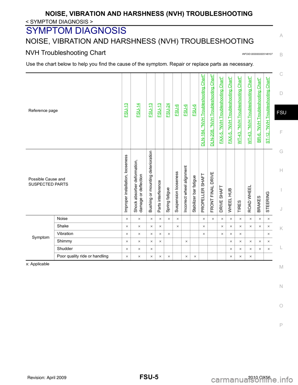
Use the chart below to help you find the cause of the symptom. Repair or replace parts as necessary.
x: ApplicableReference page
FSU-13FSU-14FSU-13FSU-13FSU-24FSU-6FSU-6FSU-6
DLN-184, "
NVH Troubleshooting Chart
"
DLN-208, "
NVH Troubleshooting Chart
"
FAX-5, "
NVH Troubleshooting Chart
"
FAX-5, "
NVH Troubleshooting Chart
"
WT-43, "
NVH Troubleshooting Chart
"
WT-43, "
NVH Troubleshooting Chart
"
BR-6, "
NVH Troubleshooting Chart
"
ST-12, "
NVH Troubleshooting Chart
"
Possible Cause and
SUSPECTED PARTS
Improper installation, looseness
Shock absorber deformation,
damage or deflection
Bushing or mounting deterioration
Parts interference
Spring fatigue
Suspension looseness
Incorrect wheel alignment
Stabilizer bar fatigue
PROPELLER SHAFT
FRONT FINAL DRIVE
DRIVE SHAFT
WHEEL HUB
TIRES
ROAD WHEEL
BRAKES
STEERING
Symptom
Noise
× × ×××× × × ×× × × ××
Shake × × ×× × × ×× × × ××
Vibration × × ××× × ×× × ×
Shimmy × × ×× × × × × ××
Shudder ××× ×××××
Poor quality ride or handling × × ××× ×× × × ×
Revision: April 20092010 QX56
Page 2205 of 4210
FSU-6
< ON-VEHICLE MAINTENANCE >
ON-VEHICLE SERVICE
ON-VEHICLE MAINTENANCE
ON-VEHICLE SERVICE
Front Suspension PartsINFOID:0000000005148108
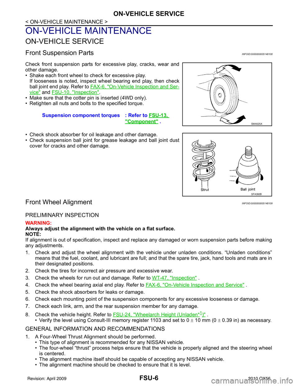
Check front suspension parts for excessive play, cracks, wear and
other damage.
• Shake each front wheel to check for excessive play.If looseness is noted, inspect wheel bearing end play, then check
ball joint end play. Refer to FA X - 6 , "
On-Vehicle Inspection and Ser-
vice" and FSU-10, "Inspection".
• Make sure that the cotter pin is inserted (4WD only).
• Retighten all nuts and bolts to the specified torque.
• Check shock absorber for oil leakage and other damage.
• Check suspension ball joint for grease leakage and ball joint dust cover for cracks and other damage.
Front Wheel AlignmentINFOID:0000000005148109
PRELIMINARY INSPECTION
WARNING:
Always adjust the alignment with the vehicle on a flat surface.
NOTE:
If alignment is out of specificat ion, inspect and replace any damaged or worn suspension parts before making
any adjustments.
1. Check and adjust the wheel alignment with the vehicle under unladen conditions. “Unladen conditions”
means that the fuel, coolant, and lubricant are full; and that the spare tire, jack, hand tools and mats are in
their designated positions.
2. Check the tires for incorrect air pressure and excessive wear.
3. Check the wheels for run out and damage. Refer to WT-47, "
Inspection" .
4. Check the wheel bearing axial end play. Refer to FA X - 6 , "
On-Vehicle Inspection and Service" .
5. Check the shock absorbers for leaks or damage.
6. Check each mounting point of the suspension components for any excessive looseness or damage.
7. Check each link, arm, and the rear suspension member for any damage.
8. Check the vehicle height. Refer to FSU-24, "
Wheelarch Height (Unladen*1)" .
• Verify the level using Consult-III memory register 1103 and set to 0 ± 10 mm (0 ± 0.39 in) as necessary.
GENERAL INFORMATION AND RECOMMENDATIONS
1. A Four-Wheel Thrust Alignment should be performed.
• This type of alignment is recommended for any NISSAN vehicle.
• The four-wheel “thrust” process helps ensure that the vehicle is properly aligned and the steering wheel
is centered.
• The alignment machine itself should be ca pable of accepting any NISSAN vehicle.
• The alignment machine should be checked to ensure that it is level. Suspension component
torques : Refer to FSU-13,
"Component" . SMA525A
SFA392B
Revision: April 20092010 QX56
Page 2212 of 4210
FRONT SUSPENSION ASSEMBLYFSU-13
< ON-VEHICLE REPAIR >
C
DF
G H
I
J
K L
M A
B
FSU
N
O P
ON-VEHICLE REPAIR
FRONT SUSPENSION ASSEMBLY
ComponentINFOID:0000000005148112
1. Dust cover 2. Shock absorber 3. Upper link
4. Steering knuckle 5. Cotter pin 6. Bolt
7. Jounce bumper 8. Washer 9. Lower link
10. Stabilizer bar 11. Stabilizer bar bushing 12. Stabilizer bar mounting bracket
13. Connecting rod 14. Coil spring 15. Upper seat
16. Upper spring seat 17. Shock absorber bushing 18. Shock absorber mounting insulator
19. Spacer 20. Washer Front
AWEIA0142GB
Revision: April 20092010 QX56
Page 2223 of 4210
FSU-24
< SERVICE DATA AND SPECIFICATIONS (SDS)
SERVICE DATA AND SPECIFICATIONS (SDS)
*2: Target value 37° 31 ′ (37.52 °)
*3: Target value 33 ° 59 ′ (33.98 °)
*4: Target value 37 ° 44 ′ (37.73 °)
*5: Target value 33 ° 29 ′ (33.48 °)
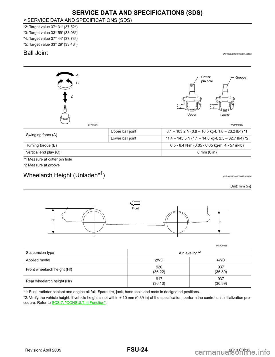
Ball JointINFOID:0000000005148123
*1 Measure at cotter pin hole
*2 Measure at groove
Wheelarch Height (Unladen*1)INFOID:0000000005148124
Unit: mm (in)
*1: Fuel, radiator coolant and engine oil full. Spare tire, jack, hand tools and mats in designated positions.
*2: Verify the vehicle height. If vehicle height is not within ± 10 mm (0.39 in) of the specification, perform the control unit initialization pro-
cedure. Refer to SCS-7, "
CONSULT-III Function".
Swinging force (A)
Upper ball joint
8.1 – 103.2 N (0.8 – 10.5 kg-f, 1.8 – 23.2 lb-f) *1
Lower ball joint 11.4 – 145.5 N (1.1 – 14.8 kg-f, 2.5 – 32.7 lb-f) *2
Turning torque (B) 0.5 - 6.4 N·m (0.05 - 0.65 kg-m, 4 - 57 in-lb)
Vertical end play (C) 0 mm (0 in)
SFA858AWEIA0076E
Suspension type
Air leveling*2
Applied model2WD4WD
Front wheelarch height (Hf) 920
(36.22) 937
(36.89)
Rear wheelarch height (Hr) 917
(36.10) 937
(36.89)
LEIA0085E
Revision: April 20092010 QX56
Page 2714 of 4210
MA-10
< ON-VEHICLE MAINTENANCE >
PERIODIC MAINTENANCE
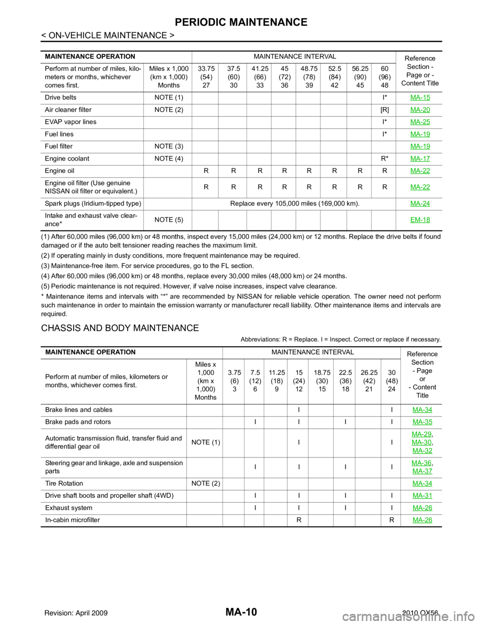
(1) After 60,000 miles (96,000 km) or 48 months, inspect every 15,000 miles (24,000 km) or 12 months. Replace the drive belts if found
damaged or if the auto belt tensioner reading reaches the maximum limit.
(2) If operating mainly in dusty conditions, more frequent maintenance may be required.
(3) Maintenance-free item. For service procedures, go to the FL section.
(4) After 60,000 miles (96,000 km) or 48 months, replace every 30,000 miles (48,000 km) or 24 months.
(5) Periodic maintenance is not required. However, if valve noise increases, inspect valve clearance.
* Maintenance items and intervals with “*” are recommended by NISSAN for reliable vehicle operation. The owner need not perform
such maintenance in order to maintain the emission warranty or manufacturer recall liability. Other maintenance items and intervals are
required.
CHASSIS AND BODY MAINTENANCE
Abbreviations: R = Replace. I = Inspec t. Correct or replace if necessary.
MAINTENANCE OPERATION MAINTENANCE INTERVAL
Reference
Section -
Page or -
Content Title
Perform at number of miles, kilo-
meters or months, whichever
comes first. Miles x 1,000
(km x 1,000) Months 33.75
(54)27 37.5
(60) 30 41.25
(66)33 45
(72) 36 48.75
(78)39 52.5
(84) 42 56.25
(90)45 60
(96) 48
Drive belts NOTE (1) I*MA-15
Air cleaner filter NOTE (2) [R]MA-20
EVAP vapor lines I*MA-25
Fuel lines I*MA-19
Fuel filter NOTE (3) MA-19
Engine coolantNOTE (4) R*MA-17
Engine oil R R R R R R R R MA-22
Engine oil filter (Use genuine
NISSAN oil filter or equivalent.)R R RRRRRR
MA-22
Spark plugs (Iridium-tipped type)Replace every 105,000 miles (169,000 km).MA-24
Intake and exhaust valve clear-
ance*NOTE (5)
EM-18
MAINTENANCE OPERATIONMAINTENANCE INTERVAL
Reference
Section- Page or
- Content Title
Perform at number of miles, kilometers or
months, whichever comes first. Miles x
1,000
(km x
1,000)
Months 3.75
(6)3 7.5
(12) 6 11 . 2 5
(18) 9 15
(24) 12 18.75
(30)15 22.5
(36) 18 26.25
(42)21 30
(48) 24
Brake lines and cables IIMA-34
Brake pads and rotors II I IMA-35
Automatic transmission fluid, transfer fluid and
differential gear oil NOTE (1)
IIMA-29,
MA-30
,
MA-32
Steering gear and linkage, axle and suspension
parts II I I
MA-36,
MA-37
Tire Rotation NOTE (2) MA-34
Drive shaft boots and propeller shaft (4WD)II I IMA-31
Exhaust system II I IMA-26
In-cabin microfilter RRMA-26
Revision: April 20092010 QX56
Page 2961 of 4210
PG
HARNESSPG-51
< COMPONENT DIAGNOSIS >
C
DE
F
G H
I
J
K L
B A
O P
N
BODY HARNESS
C3 C6 B/2 : Evap canister vent control valve B4 C103 B/3 : Rear sonar sensor LH inner
B4 C7 GR/2 : Rear bumper antenna
B4 C104 B/3 : Rear sonar sensor RH inner
C4 C8 B/3 : Height sensor C5 C105 B/3 : Rear sonar sensor RH outer
B4 C9 B/4 : Suspension air compressor
ABMIA0158GB
Revision: April 20092010 QX56
Page 2962 of 4210

PG-52
< COMPONENT DIAGNOSIS >
HARNESS
G3 B3 W/16 : Suspension control unitC5 B69 SMJ : To M40
E4 B6 W/18 : To D201 G2 B70 GR/3 : Rear combination lamp LH
C5 B7 — : Body ground D5 B72 BR/6 : Subwoofer
D4 B8 W/3 : Front door switch LH F3 B73 W/16 : Rear view camera control unit
C4 B9 Y/12 : Air bag diagnosis sensor unit C4 B74 Y/4 : Seat belt buckle pre-tensioner assembly LH
E5 B10 Y/2 : Front LH side air bag module F2 B75 W/10 : To B400
F3 B13 W/24 : ICC unit F2 B76 GR/2 : Luggage area antenna
E5 B14 Y/2 : Front LH seat belt pre-tensioner C3 B78 W/3 : Rear seat heater RH
E5 B15 Y/2 : LH side air bag (satellite) sensor E3 B79 W/3 : Rear seat heater LH
G3 B17 GR/24 : ICC unit Front seat LH harness
E3 B18 W/3 : Rear door switch LH D3 B200 W/16 : To B37
G1 B19 — : Body ground D5 B202 W/32 : Driver seat control unit
G2 B24 W/16 : Sonar control unit D5 B203 W/16 : Driver seat control unit
B4 B32 W/6 : To B124 C5 B204 GR/5 : Sliding motor LH
G2 B35 B/3 : Rear combination lamp LH D3 B205 W/4 : Reclining motor LH
D3 B37 W/16 : To B200 C4 B206 GR/5 : Lifting motor (front)
C5 B38 Y/2 : LH side front curtain air bag module D4 B207 GR/5 : Lifting motor (rear)
C5 B40 W/24 : To E34 D4 B208 W/10 : Power seat switch LH
C5 B41 W/12 : To E35 D4 B209 W/3 : Front seat heater LH
C5 B42 W/2 : To E36 D5 B210 W/4 : Lumbar support switch
B4 B43 W/16 : To B111 E5 B211 B/2 : Lumbar support motor
F1 B48 W/18 : To D401 Third row power folding seat sub-harness
F1 B49 W/2 : To D402 F2 B400 W/10 : To B75
F2 B52 W/2 : Rear power vent window motor LH E3 B401 GR/12 : Third row power folding seat control unit
F2 B54 Y/2 : LH side rear curtain air bag module E3 B402 W/10 : Third row power folding seat control unit
G3 B55 W/26 : Back door control unit F3 B403 GR/4 : Third row power folding seat motor LH
F2 B56 GR/16 : Sonar control unit (with front and rear
sonar system) E2 B404 W/4 : To B425
G2 B57 GR/10 : Sonar control unit (with front and rear
sonar system) E3 B425 W/4 : To B404
G1 B63 W/6 : Back door close switch E2 B426 GR/4 : Third row power folding seat motor RH
Revision: April 20092010 QX56