2010 INFINITI QX56 stop start
[x] Cancel search: stop startPage 2455 of 4210
![INFINITI QX56 2010 Factory Service Manual INSUFFICIENT COOLINGHAC-115
< SYMPTOM DIAGNOSIS > [AUTOMATIC AIR CONDITIONER]
C
D
E
F
G H
J
K L
M A
B
HAC
N
O P
Low-pressure Side Becomes Negative
Gauge indication
Refrigerant cycleProbable causeCorre INFINITI QX56 2010 Factory Service Manual INSUFFICIENT COOLINGHAC-115
< SYMPTOM DIAGNOSIS > [AUTOMATIC AIR CONDITIONER]
C
D
E
F
G H
J
K L
M A
B
HAC
N
O P
Low-pressure Side Becomes Negative
Gauge indication
Refrigerant cycleProbable causeCorre](/manual-img/42/57032/w960_57032-2454.png)
INSUFFICIENT COOLINGHAC-115
< SYMPTOM DIAGNOSIS > [AUTOMATIC AIR CONDITIONER]
C
D
E
F
G H
J
K L
M A
B
HAC
N
O P
Low-pressure Side Becomes Negative
Gauge indication
Refrigerant cycleProbable causeCorrective action
Low-pressure side sometimes be-
comes negative. • Air conditioning system does
not function and does not cy-
clically cool the compart-
ment air.
• The system constantly func- tions for a certain period of
time after compressor is
stopped and restarted. Refrigerant does not discharge
cyclically.
↓
Moisture is frozen at expan-
sion valve outlet and inlet.
↓
Water is mixed with refrigerant.
• Drain water from refrigerant
or replace refrigerant.
• Replace liquid tank.
AC354A
Gauge indication Refrigerant cycleProbable causeCorrective action
Low-pressure side becomes nega-
tive. Liquid tank or front/rear side of
expansion valve′s pipe is frost-
ed or dewed. High-pressure side is closed
and refrigerant does not flow.
↓
Expansion valve or liquid tank
is frosted.Leave the system at rest until
no frost is present. Start it
again to check whether or not
the malfunction is caused by
water or foreign particles.
• If water is the cause, initially
cooling is okay. Then the wa-
ter freezes causing a block-
age. Drain water from
refrigerant or replace refrig-
erant.
• If due to foreign particles, re- move expansion valve and
remove the particles with dry
and compressed air (not
shop air).
• If either of the above meth- ods cannot correct the mal-
function, replace expansion
valve.
• Replace liquid tank.
• Check oil for contamination.
AC362A
Revision: April 20092010 QX56
Page 2556 of 4210

INT-4
< SYMPTOM DIAGNOSIS >
SQUEAK AND RATTLE TROUBLE DIAGNOSES
68370-4B000: 15×25 mm (0.59× 0.98 in) pad/68239-13E00: 5 mm (0.20 in ) wide tape roll. The following
materials not found in the kit can also be used to repair squeaks and rattles.
UHMW (TEFLON) TAPE
Insulates where slight movement is present. Ideal for inst rument panel applications.
SILICONE GREASE
Used instead of UHMW tape that will be visible or not fit.
Note: Will only last a few months.
SILICONE SPRAY
Use when grease cannot be applied.
DUCT TAPE
Use to eliminate movement.
CONFIRM THE REPAIR
Confirm that the cause of a noise is repaired by test driving the vehicle. Operate the vehicle under the same
conditions as when the noise originally occurred. Refer to the notes on the Diagnostic Worksheet.
Generic Squeak and Rattle TroubleshootingINFOID:0000000005147343
Refer to Table of Contents for specific component removal and installation information.
INSTRUMENT PANEL
Most incidents are caused by contact and movement between:
1. The cluster lid A and instrument panel
2. Acrylic lens and combination meter housing
3. Instrument panel to front pillar garnish
4. Instrument panel to windshield
5. Instrument panel pins
6. Wiring harnesses behind the combination meter
7. A/C defroster duct and duct joint
These incidents can usually be located by tapping or moving the components to duplicate the noise or by
pressing on the components while driving to stop the noise. Most of these incidents can be repaired by apply-
ing felt cloth tape or silicone spray (in hard to reach areas). Urethane pads can be used to insulate wiring har-
ness.
CAUTION:
Do not use silicone spray to isolate a squeak or rattle. If you saturate the ar ea with silicone, you will
not be able to recheck the repair.
CENTER CONSOLE
Components to pay attention to include:
1. Shifter assembly cover to finisher
2. A/C control unit and cluster lid C
3. Wiring harnesses behind audio and A/C control unit
The instrument panel repair and isolation pr ocedures also apply to the center console.
DOORS
Pay attention to the:
1. Finisher and inner panel making a slapping noise
2. Inside handle escutcheon to door finisher
3. Wiring harnesses tapping
4. Door striker out of alignment causing a popping noise on starts and stops
Tapping or moving the components or pressing on them wh ile driving to duplicate the conditions can isolate
many of these incidents. You can usually insulate the areas with felt cloth tape or insulator foam blocks from
the NISSAN Squeak and Rattle Kit (J-43980) to repair the noise.
TRUNK
Trunk noises are often caused by a loose jack or loose items put into the trunk by the owner.
In addition look for:
1. Trunk lid bumpers out of adjustment
Revision: April 20092010 QX56
Page 2580 of 4210
SQUEAK AND RATTLE TROUBLE DIAGNOSESIP-7
< SYMPTOM DIAGNOSIS >
C
DE
F
G H
I
K L
M A
B
IP
N
O P
68370-4B000: 15 ×25 mm (0.59 ×0.98 in) pad/68239-13E00: 5 mm (0.20 in) wide tape roll
The following materials, not found in the kit, can also be used to repair squeaks and rattles.
UHMW (TEFLON) TAPE
Insulates where slight movement is present. Ideal for instrument panel applications.
SILICONE GREASE
Used in place of UHMW tape that will be visible or not fit. Will only last a few months.
SILICONE SPRAY
Use when grease cannot be applied.
DUCT TAPE
Use to eliminate movement.
CONFIRM THE REPAIR
Confirm that the cause of a noise is repaired by test driving the vehicle. Operate the vehicle under the same
conditions as when the noise originally occurred. Refer to the notes on the Diagnostic Worksheet.
Generic Squeak and Rattle TroubleshootingINFOID:0000000005147359
Refer to Table of Contents for specific component removal and installation information.
INSTRUMENT PANEL
Most incidents are caused by contact and movement between:
1. The cluster lid A and instrument panel
2. Acrylic lens and combination meter housing
3. Instrument panel to front pillar garnish
4. Instrument panel to windshield
5. Instrument panel mounting pins
6. Wiring harnesses behind the combination meter
7. A/C defroster duct and duct joint
These incidents can usually be located by tapping or moving the components to duplicate the noise or by
pressing on the components while driving to stop the noi se. Most of these incidents can be repaired by apply-
ing felt cloth tape or silicone spray (in hard to reach areas). Urethane pads can be used to insulate wiring har-
ness.
CAUTION:
Do not use silicone spray to isolate a squeak or ra ttle. If you saturate the area with silicone, you will
not be able to recheck the repair.
CENTER CONSOLE
Components to pay attention to include:
1. Shifter assembly cover to finisher
2. A/C control unit and cluster lid C
3. Wiring harnesses behind audio and A/C control unit
The instrument panel repair and isolation pr ocedures also apply to the center console.
DOORS
Pay attention to the:
1. Finisher and inner panel making a slapping noise
2. Inside handle escutcheon to door finisher
3. Wiring harnesses tapping
4. Door striker out of alignment causing a popping noise on starts and stops
Tapping or moving the components or pressing on them while driving to duplicate the conditions can isolate
many of these incidents. You can usually insulate the ar eas with felt cloth tape or insulator foam blocks from
the NISSAN Squeak and Rattle Kit (J-43980) to repair the noise.
TRUNK
Trunk noises are often caused by a loose jack or loose items put into the trunk by the owner.
In addition look for:
1. Trunk lid bumpers out of adjustment
2. Trunk lid striker out of adjustment
Revision: April 20092010 QX56
Page 2695 of 4210
ENGINE OILLU-9
< ON-VEHICLE MAINTENANCE >
C
DE
F
G H
I
J
K L
M A
LU
NP
O
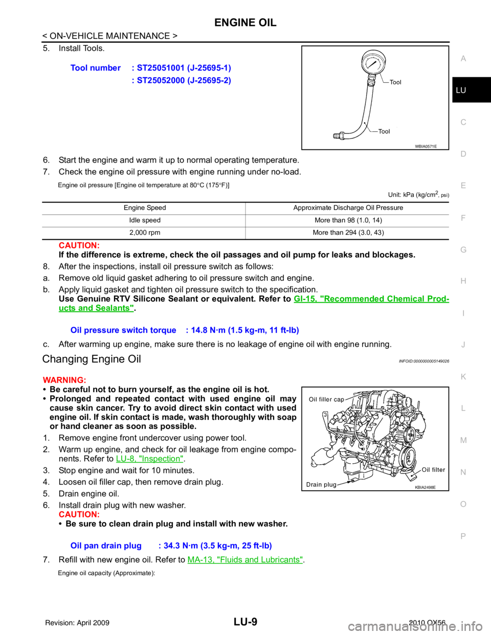
5. Install Tools.
6. Start the engine and warm it up to normal operating temperature.
7. Check the engine oil pressure with engine running under no-load.
Engine oil pressure [Engine oil temperature at 80
°C (175 °F)]
Unit: kPa (kg/cm2, psi)
CAUTION:
If the difference is extreme, check the oil passages and oil pump for leaks and blockages.
8. After the inspections, install oil pressure switch as follows:
a. Remove old liquid gasket adhering to oil pressure switch and engine.
b. Apply liquid gasket and tighten oil pressure switch to the specification. Use Genuine RTV Silicone Seal ant or equivalent. Refer to GI-15, "
Recommended Chemical Prod-
ucts and Sealants".
c. After warming up engine, make sure there is no leakage of engine oil with engine running.
Changing Engine OilINFOID:0000000005149026
WARNING:
• Be careful not to burn yourself, as the engine oil is hot.
• Prolonged and repeated contact with used engine oil may cause skin cancer. Try to avoid direct skin contact with used
engine oil. If skin contact is made, wash thoroughly with soap
or hand cleaner as soon as possible.
1. Remove engine front undercover using power tool.
2. Warm up engine, and check for oil leakage from engine compo- nents. Refer to LU-8, "
Inspection".
3. Stop engine and wait for 10 minutes.
4. Loosen oil filler cap, then remove drain plug.
5. Drain engine oil.
6. Install drain plug with new washer. CAUTION:
• Be sure to clean drain plug and install with new washer.
7. Refill with new engine oil. Refer to MA-13, "
Fluids and Lubricants".
Engine oil capacity (Approximate):
Tool number : ST25051001 (J-25695-1)
: ST25052000 (J-25695-2)
WBIA0571E
Engine Speed Approximate Discharge Oil Pressure
Idle speed More than 98 (1.0, 14)
2,000 rpm More than 294 (3.0, 43)
Oil pressure switch torque : 14.8 N·m (1.5 kg-m, 11 ft-lb)
Oil pan drain plug : 34.3 N·m (3.5 kg-m, 25 ft-lb)
KBIA2498E
Revision: April 20092010 QX56
Page 2697 of 4210
OIL FILTERLU-11
< ON-VEHICLE MAINTENANCE >
C
DE
F
G H
I
J
K L
M A
LU
NP
O
OIL FILTER
Removal and InstallationINFOID:0000000005149027
REMOVAL
1. Drain the engine oil. Refer to
LU-9, "Changing Engine Oil".
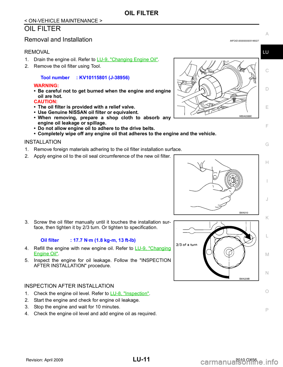
2. Remove the oil filter using Tool.
WARNING:
• Be careful not to get burned when the engine and engine
oil are hot.
CAUTION:
• The oil filter is provided with a relief valve.
• Use Genuine NISSAN oil filter or equivalent.
• When removing, prepare a s hop cloth to absorb any
engine oil leakage or spillage.
• Do not allow engine oil to adhere to the drive belts.
• Completely wipe off any engine oil that adheres to the engine and the vehicle.
INSTALLATION
1. Remove foreign materials adhering to the oil filter installation surface.
2. Apply engine oil to the oil seal circumference of the new oil filter.
3. Screw the oil filter manually until it touches the installation sur-
face, then tighten it by 2/3 turn. Or tighten to specification.
4. Refill the engine with new engine oil. Refer to LU-9, "
Changing
Engine Oil".
5. Inspect the engine for oil leakage. Follow the "INSPECTION AFTER INSTALLATION" procedure.
INSPECTION AFTER INSTALLATION
1. Check the engine oil level. Refer to LU-8, "Inspection".
2. Start the engine and check for engine oil leakage.
3. Stop the engine and wait for 10 minutes.
4. Check the engine oil level and add engine oil as required. Tool number : KV10115801 (J-38956)
WBIA0388E
SMA010
Oil filter : 17.7 N·m (1.8 kg-m, 13 ft-lb)
SMA229B
Revision: April 20092010 QX56
Page 2699 of 4210
OIL COOLERLU-13
< ON-VEHICLE REPAIR >
C
DE
F
G H
I
J
K L
M A
LU
NP
O
Relief Valve
Inspect relief valve for movement, cracks and breaks by
pushing the ball. If replacement is necessary, remove
the valve by prying it out using a suitable tool. Install a new valve in place by tapping it.
INSTALLATION
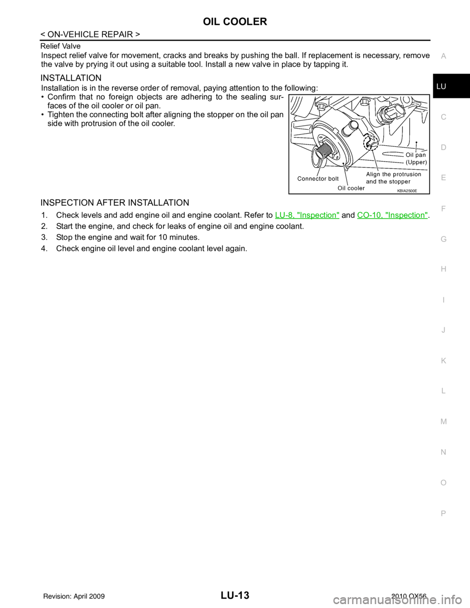
Installation is in the reverse order of removal, paying attention to the following:
• Confirm that no foreign objects are adhering to the sealing sur- faces of the oil cooler or oil pan.
• Tighten the connecting bolt after aligning the stopper on the oil pan side with protrusion of the oil cooler.
INSPECTION AFTER INSTALLATION
1. Check levels and add engine oil and engine coolant. Refer to LU-8, "Inspection" and CO-10, "Inspection".
2. Start the engine, and check for leaks of engine oil and engine coolant.
3. Stop the engine and wait for 10 minutes.
4. Check engine oil level and engine coolant level again.
KBIA2500E
Revision: April 20092010 QX56
Page 2701 of 4210
OIL PUMPLU-15
< ON-VEHICLE REPAIR >
C
DE
F
G H
I
J
K L
M A
LU
NP
O
• Start the engine, and check for leaks of engine oil.
• Stop engine and wait 10 minutes.
• Check level and add engine oil as required. Refer to
LU-8
.
Revision: April 20092010 QX56
Page 2727 of 4210
ENGINE MAINTENANCEMA-23
< ON-VEHICLE MAINTENANCE >
C
DE
F
G H
I
J
K L
M B
MA
N
O A
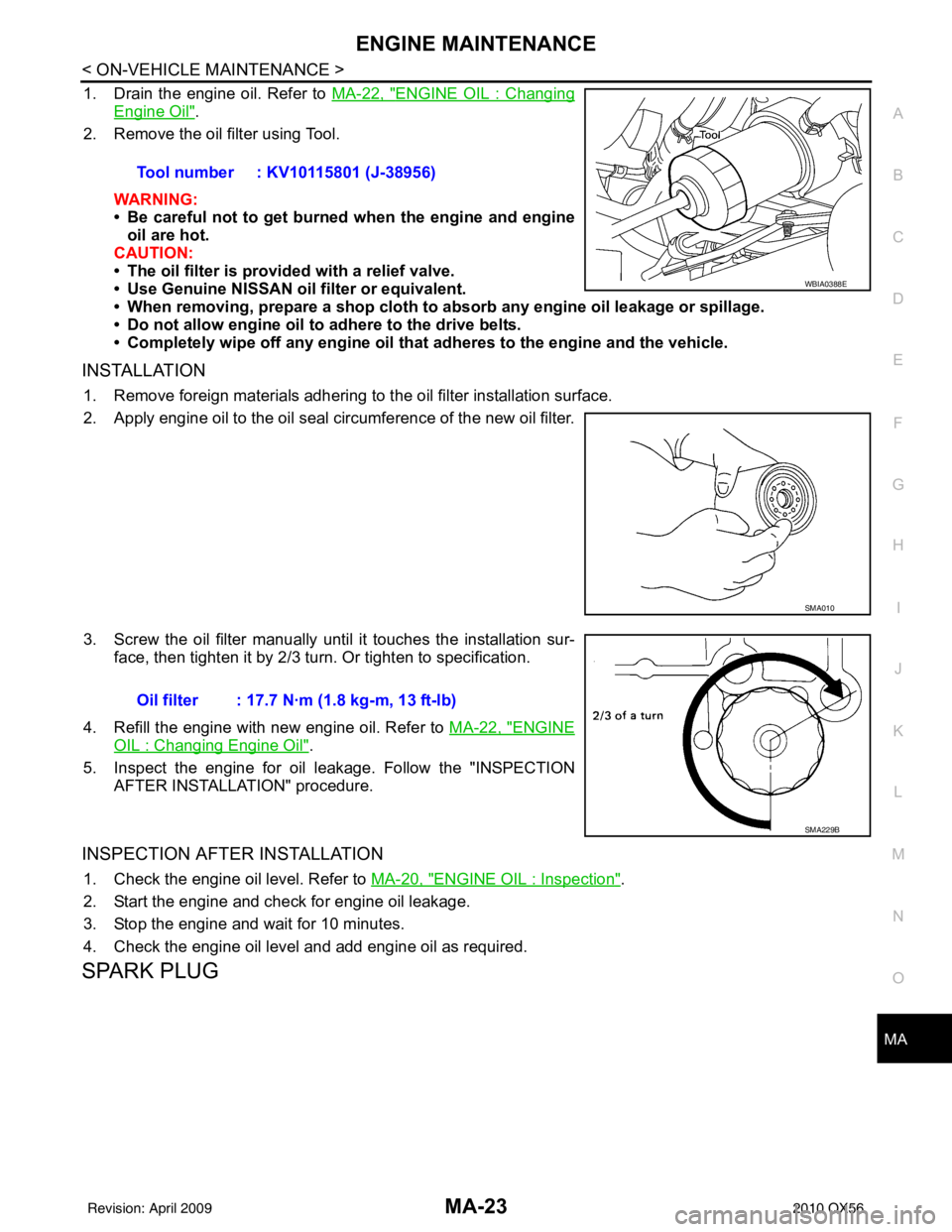
1. Drain the engine oil. Refer to
MA-22, "ENGINE OIL : Changing
Engine Oil".
2. Remove the oil filter using Tool.
WARNING:
• Be careful not to get burned when the engine and engine
oil are hot.
CAUTION:
• The oil filter is provided with a relief valve.
• Use Genuine NISSAN oil filter or equivalent.
• When removing, prepare a shop cloth to ab sorb any engine oil leakage or spillage.
• Do not allow engine oil to adhere to the drive belts.
• Completely wipe off any engine oil that adheres to the engine and the vehicle.
INSTALLATION
1. Remove foreign materials adhering to the oil filter installation surface.
2. Apply engine oil to the oil seal circumference of the new oil filter.
3. Screw the oil filter manually until it touches the installation sur-
face, then tighten it by 2/3 turn. Or tighten to specification.
4. Refill the engine with new engine oil. Refer to MA-22, "
ENGINE
OIL : Changing Engine Oil".
5. Inspect the engine for oil leakage. Follow the "INSPECTION AFTER INSTALLATION" procedure.
INSPECTION AFTER INSTALLATION
1. Check the engine oil level. Refer to MA-20, "ENGINE OIL : Inspection".
2. Start the engine and check for engine oil leakage.
3. Stop the engine and wait for 10 minutes.
4. Check the engine oil level and add engine oil as required.
SPARK PLUG
Tool number : KV10115801 (J-38956)
WBIA0388E
SMA010
Oil filter : 17.7 N·m (1.8 kg-m, 13 ft-lb)
SMA229B
Revision: April 20092010 QX56