Page 4105 of 4210
WT-36
< SYMPTOM DIAGNOSIS >
TPMS
SYMPTOM DIAGNOSIS
TPMS
Symptom TableINFOID:0000000005148234
SymptomReference
Low tire pressure warning lamp does not come on when ignition switch is turned ON. WT-37
Low tire pressure warning lamp stays on when ignition switch is turned ON.WT-38
Low tire pressure warning lamp flashes when ignition switch is turned ON.WT-39
Hazard warning lamps flash when ignition switch is turned ON.WT-40
Tire pressure information in display unit does not exist.WT-42
ID registration cannot be completed.WT-42
Revision: April 20092010 QX56
Page 4106 of 4210

LOW TIRE PRESSURE WARNING LAMP DOES NOT TURN ON
WT-37
< SYMPTOM DIAGNOSIS >
C
D F
G H
I
J
K L
M A
B
WT
N
O P
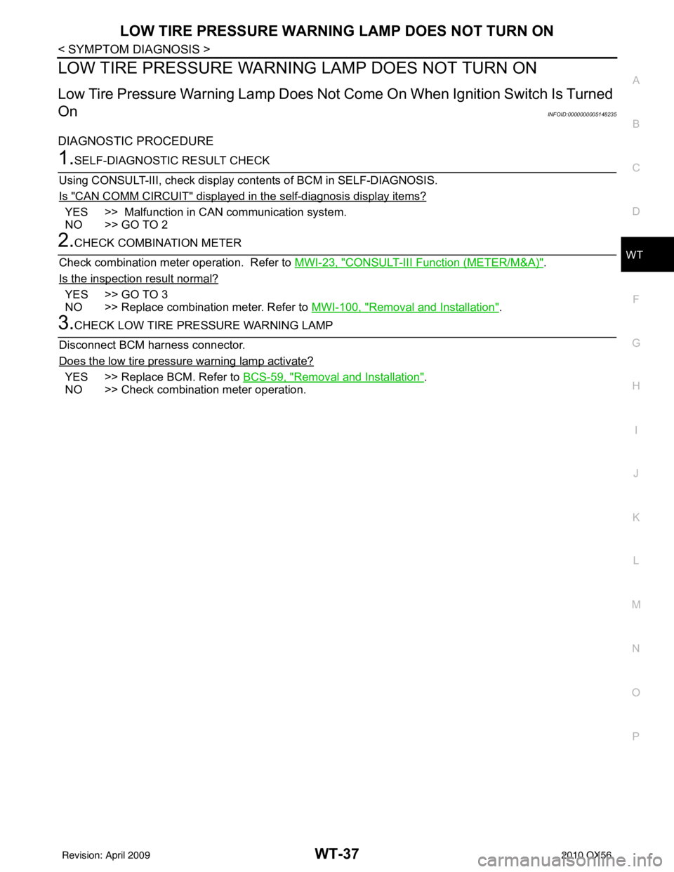
LOW TIRE PRESSURE WARNIN G LAMP DOES NOT TURN ON
Low Tire Pressure Warning Lamp Does Not Come On When Ignition Switch Is Turned
On
INFOID:0000000005148235
DIAGNOSTIC PROCEDURE
1.SELF-DIAGNOSTIC RESULT CHECK
Using CONSULT-III, check display contents of BCM in SELF-DIAGNOSIS.
Is "CAN COMM CIRCUIT" displayed in the self-diagnosis display items?
YES >> Malfunction in CAN communication system.
NO >> GO TO 2
2.CHECK COMBINATION METER
Check combination meter operation. Refer to MWI-23, "
CONSULT-III Function (METER/M&A)".
Is the inspection result normal?
YES >> GO TO 3
NO >> Replace combination meter. Refer to MWI-100, "
Removal and Installation".
3.CHECK LOW TIRE PRE SSURE WARNING LAMP
Disconnect BCM harness connector.
Does the low tire pressure warning lamp activate?
YES >> Replace BCM. Refer to BCS-59, "Removal and Installation".
NO >> Check combination meter operation.
Revision: April 20092010 QX56
Page 4107 of 4210
WT-38
< SYMPTOM DIAGNOSIS >
LOW TIRE PRESSURE WARNING LAMP STAYS ON
LOW TIRE PRESSURE WARNING LAMP STAYS ON
Low Tire Pressure Warning Lamp Stays On When Ignition Switch Is Turned On
INFOID:0000000005148236
DIAGNOSTIC PROCEDURE
1.BCM CONNECTORS
1. Turn ignition switch OFF.
2. Disconnect BCM harness connectors.
3. Check terminals for damage or loose connections.
Is the inspection result normal?
YES >> GO TO 2
NO >> Repair or replace damaged parts.
2.BCM POWER SUPPLY AND GROUND CIRCUITS
Check BCM power supply and ground circuits. Refer to BCS-33, "
Diagnosis Procedure".
Is the inspection result normal?
YES >> Replace BCM. Refer to BCS-59, "Removal and Installation".
NO >> Repair BCM circuits.
Revision: April 20092010 QX56
Page 4108 of 4210

LOW TIRE PRESSURE WARNING LAMP BLINKSWT-39
< SYMPTOM DIAGNOSIS >
C
DF
G H
I
J
K L
M A
B
WT
N
O P
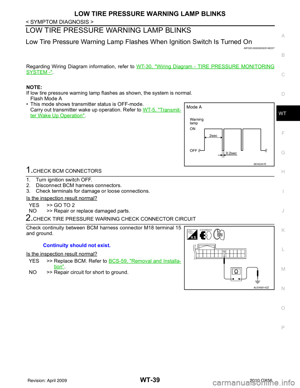
LOW TIRE PRESSURE WA RNING LAMP BLINKS
Low Tire Pressure Warning Lamp Flas hes When Ignition Switch Is Turned On
INFOID:0000000005148237
Regarding Wiring Diagram information, refer to WT-30, "Wiring Diagram - TIRE PRESSURE MONITORING
SYSTEM -".
NOTE:
If low tire pressure warning lamp fl ashes as shown, the system is normal.
Flash Mode A
• This mode shows transmitter status is OFF-mode.
Carry out transmitter wake up operation. Refer to WT-5, "
Transmit-
ter Wake Up Operation".
1.CHECK BCM CONNECTORS
1. Turn ignition switch OFF.
2. Disconnect BCM harness connectors.
3. Check terminals for damage or loose connections.
Is the inspection result normal?
YES >> GO TO 2
NO >> Repair or replace damaged parts.
2.CHECK TIRE PRESSURE WARNING CHECK CONNECTOR CIRCUIT
Check continuity between BCM harness connector M18 terminal 15
and ground.
Is the inspection result normal?
YES >> Replace BCM. Refer to BCS-59, "Removal and Installa-
tion".
NO >> Repair circuit for short to ground.
SEIA0347E
Continuity should not exist.
ALEIA0014ZZ
Revision: April 20092010 QX56
Page 4110 of 4210
"TIRE PRESSURE" INFORMATION IN DISPLAY UNIT DOES NOT EXIST
WT-41
< SYMPTOM DIAGNOSIS >
C
D F
G H
I
J
K L
M A
B
WT
N
O P
"TIRE PRESSURE" INFORMATION IN DISPLAY UNIT DOES NOT EXIST
"TIRE PRESSURE" Information in Display Unit Does Not ExistINFOID:0000000005148239
DIAGNOSTIC PROCEDURE
1.SELF-DIAGNOSTIC RESULT CHECK
Using CONSULT-III, check display contents in self-diagnostic results.
Is "CAN COMM CIRCUIT" displayed in the self-diagnosis display items?
YES >> Malfunction in CAN communication system.
NO >> GO TO 2.
2.CHECK DISPLAY UNIT
Perform display unit self-diagnosis. Refer to AV-38, "
AV CONTROL UNIT : CONSULT-III Function".
Is the inspection result normal?
YES >> Replace BCM. Refer to BCS-59, "Removal and Installation".
NO >> Repair or replace malfunctioning parts.
Revision: April 20092010 QX56
Page 4112 of 4210

NOISE, VIBRATION AND HARSHNESS (NVH) TROUBLESHOOTINGWT-43
< SYMPTOM DIAGNOSIS >
C
DF
G H
I
J
K L
M A
B
WT
N
O P
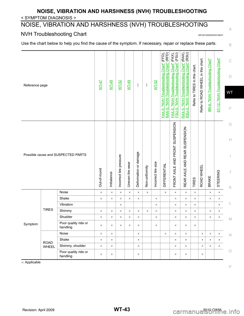
NOISE, VIBRATION AND HARSHN ESS (NVH) TROUBLESHOOTING
NVH Troubleshooting ChartINFOID:0000000005148241
Use the chart below to help you find t he cause of the symptom. If necessary, repair or replace these parts.
×: ApplicableReference page
WT-47WT-48WT-52WT-49—
—
WT-52
FA X - 5 , "
NVH Troubleshooting Chart
" (FFD),
RAX-5, "
NVH Troubleshooting Chart
" (RFD)
FA X - 5 , "
NVH Troubleshooting Chart
" (FAX),
FSU-5, "
NVH Troubleshooting Chart
" (FSU)
RAX-5, "
NVH Troubleshooting Chart
" (RAX),
RSU-5, "
NVH Troubleshooting Chart
" (RSU)
Refer to TIRES in this chart.
Refer to ROAD WHEEL in this chart.
BR-6, "
NVH Troubleshooting Chart
"
ST-12, "
NVH Troubleshooting Chart
"
Possible cause and SUSPECTED PARTS
Out-of-round
Imbalance
Incorrect tire pressure
Uneven tire wear
Deformation or damage
Non-uniformity
Incorrect tire size
DIFFERENTIAL
FRONT AXLE AND FRONT SUSPENSION
REAR AXLE AND REAR SUSPENSION
TIRES
ROAD WHEEL
BRAKE
STEERING
Symptom TIRESNoise
× ××××× × × ×× ××
Shake × ×××× × × ×× ××
Vibration ××× ×××
Shimmy × ×××××× × ×× ××
Shudder × ×××× × × ×× ××
Poor quality ride or
handling × ×××× × × ××
ROAD
WHEEL Noise
×× × ××× ×××
Shake ×× × ×× ×××
Shimmy, shudder ×× × ×× ×××
Poor quality ride or
handling ×× ×
×× ×
Revision: April 20092010 QX56
Page 4118 of 4210

WHEEL AND TIRE ASSEMBLYWT-49
< ON-VEHICLE REPAIR >
C
DF
G H
I
J
K L
M A
B
WT
N
O P
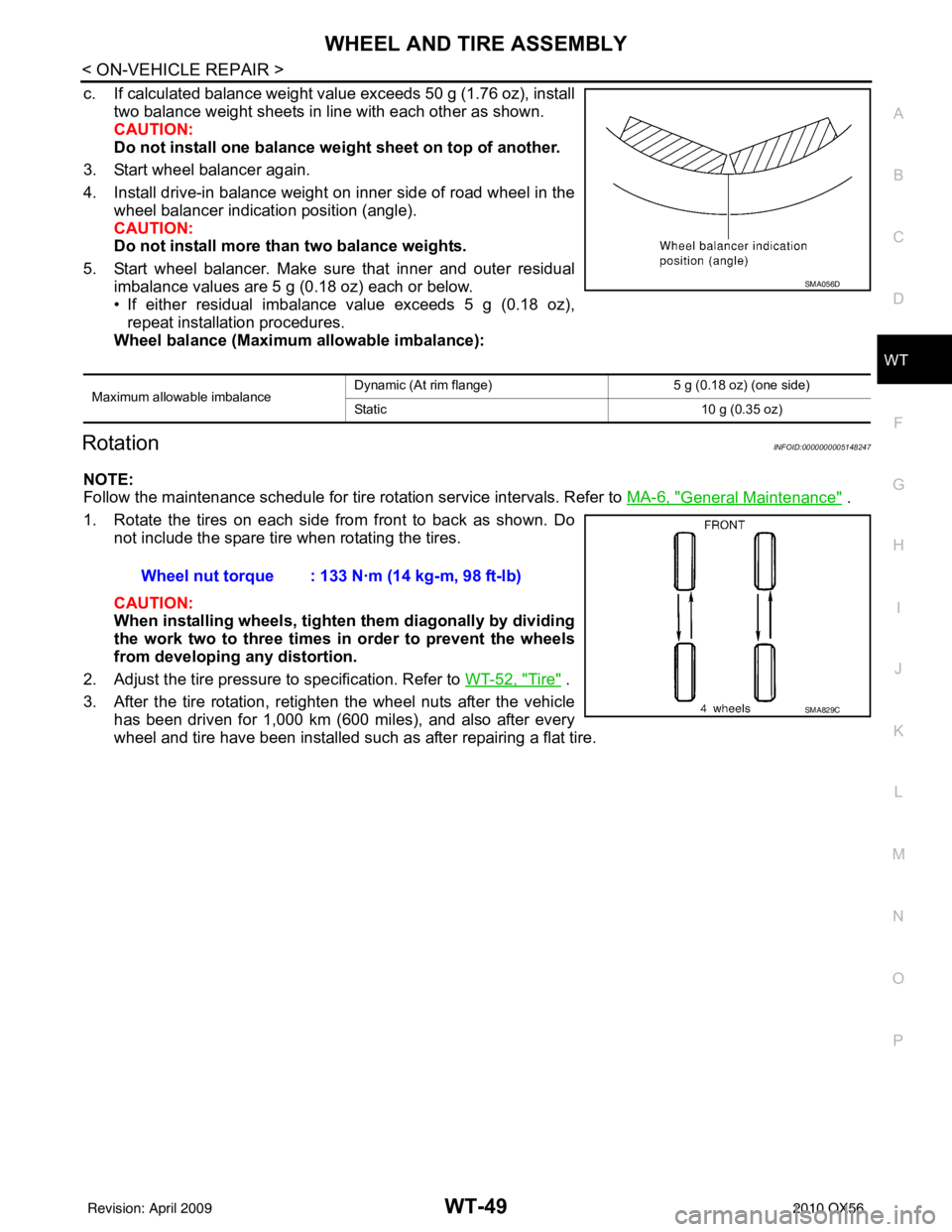
c. If calculated balance weight value exceeds 50 g (1.76 oz), install two balance weight sheets in line with each other as shown.
CAUTION:
Do not install one balance weig ht sheet on top of another.
3. Start wheel balancer again.
4. Install drive-in balance weight on inner side of road wheel in the wheel balancer indication position (angle).
CAUTION:
Do not install more than two balance weights.
5. Start wheel balancer. Make sure that inner and outer residual imbalance values are 5 g (0.18 oz) each or below.
• If either residual imbalance value exceeds 5 g (0.18 oz),repeat installation procedures.
Wheel balance (Maximum allowable imbalance):
RotationINFOID:0000000005148247
NOTE:
Follow the maintenance schedule for tire rotation service intervals. Refer to MA-6, "
General Maintenance" .
1. Rotate the tires on each side from front to back as shown. Do not include the spare tire when rotating the tires.
CAUTION:
When installing wheel s, tighten them diagonally by dividing
the work two to three times in order to prevent the wheels
from developing any distortion.
2. Adjust the tire pressure to specification. Refer to WT-52, "
Tire" .
3. After the tire rotation, retighten the wheel nuts after the vehicle has been driven for 1,000 km (600 miles), and also after every
wheel and tire have been installed such as after repairing a flat tire.
Maximum allowable imbalance Dynamic (At rim flange) 5 g (0.18 oz) (one side)
Static
10 g (0.35 oz)
SMA056D
Wheel nut torque : 133 N·m (14 kg-m, 98 ft-lb)
SMA829C
Revision: April 20092010 QX56
Page 4119 of 4210

WT-50
< REMOVAL AND INSTALLATION >
REMOVAL AND INSTALLATION
REMOVAL AND INSTALLATION
REMOVAL AND INSTALLATION
Transmitter (Pressure Sensor)INFOID:0000000005148248
REMOVAL
1. Deflate tire. Unscrew transmitter retaining nut and allow transmitter to fall into tire.
2. Gently bounce tire so that trans mitter falls to bottom of tire.
Place wheel and tire assembly on tire changing machine and
break both tire beads. Ensure that the transmitter remains at the
bottom of the tire while breaking the bead.
3. Turn tire so that valve hole is at bottom, and gently bounce the tire to ensure transmitter is near valve hole. Carefully lift tire onto
turntable and position valve hole (and transmitter) 270 degrees
from mounting/dismounting head.
4. Lubricate tire well, and remove top side of tire. Reach inside the tire and remove the transmitter.
5. Remove the second side of the tire as normal.
INSTALLATION
1. Place first side of tire onto rim.
2. Mount transmitter on rim and tighten nut to specification.
SEIA0047E
WEIA0046E
SEIA0049E
Transmitter nut : 7.7 N·m (0.79 kg-m, 68 in-lb)
WEIA0137E
Revision: April 20092010 QX56