2010 INFINITI QX56 engine
[x] Cancel search: enginePage 3855 of 4210
TM-160
< ON-VEHICLE MAINTENANCE >
ROAD TEST
YES >> Record the malfunction, GO TO 4.
NO >> GO TO 4.
4.CHECK “N” POSITION FUNCTIONS
1. Start the engine.
2. Move selector lever to “N” position.
3. Release the parking brake.
Does vehicle move forward or backward?
YES >> Record the malfunction, GO TO 5.
NO >> GO TO 5.
5.CHECK SHIFT SHOCK
1. Engage the brake.
2. Move selector lever to “D” position.
When the transmission is shifted from
“N” to “D”, is there an excessive shock?
YES >> Record the malfunction, GO TO 6.
NO >> GO TO 6.
6.CHECK “R” POSITION FUNCTIONS
1. Engage the brake.
2. Move selector lever to “R” position.
3. Release the brake for 4 to 5 seconds.
Does the vehicle creep backward?
YES >> GO TO 7.
NO >> Record the malfunction, GO TO 7.
7.CHECK “D” POSITION FUNCTIONS
Inspect whether the vehicle creeps forward when the transmission is put into the “D” position.
Does the vehicle creep forward in the
“D” positions?
YES >> Go to TM-160, "Cruise Test - Part 1".
NO >> Record the malfunction and go to TM-160, "
Cruise Test - Part 1".
Cruise Test - Part 1INFOID:0000000005148731
1.CHECK STARTING OUT FROM D1
1. Drive the vehicle for about 10 minutes to warm up the engine oil and ATF. Appropriate temperature for the ATF: 50 - 80° C (122 - 176°F)
2. Park the vehicle on a level surface.
3. Move selector lever to “P” position.
4. Start the engine.
5. Move selector lever to “D” position.
6. Press the accelerator pedal about half way down to accelerate the vehicle.
With CONSULT-III
Read off the gear positions.
Starts from D1?
YES >> GO TO 2.
NO >> Record the malfunction, GO TO 2.
2.CHECK SHIFT-UP D1 → D2
Press down the accelerator pedal about half way and inspect if the vehicle shifts up (D1 → D2) at the appropri-
ate speed.
• Refer to TM-265, "
Vehicle Speed at Which Gear Shifting Occurs".
With CONSULT-III
Read the gear position, throttle degree of opening, and vehicle speed.
Does the A/T shift-up D1
→ D2 at the correct speed?
YES >> GO TO 3.
NO >> Record the malfunction, GO TO 3.
Revision: April 20092010 QX56
Page 3857 of 4210
TM-162
< ON-VEHICLE MAINTENANCE >
ROAD TEST
With CONSULT-III
Read the gear position and engine speed.
When the A/T shift-down D5
→ D4, does the engine speed drop smoothly back to idle?
YES >> 1. Stop the vehicle. 2. Go to TM-162, "
Cruise Test - Part 2".
NO >> Record the malfunction and go to TM-162, "
Cruise Test - Part 2".
Cruise Test - Part 2INFOID:0000000005148732
1.CHECK STARTING FROM D1
1. Move selector lever the “D” position.
2. Accelerate at half throttle. With CONSULT-III
Read the gear position.
Does it start from D1?
YES >> GO TO 2.
NO >> Record the malfunction, GO TO 2.
2.CHECK SHIFT-UP D1 → D2
Press the accelerator pedal down all the way and ins pect whether or not the transmission shifts up (D1 → D2)
at the correct speed.
• Refer to TM-265, "
Vehicle Speed at Which Gear Shifting Occurs".
With CONSULT-III
Read the gear position, throttle position and vehicle speed.
Does the A/T shift-up D1
→ D2 at the correct speed?
YES >> GO TO 3.
NO >> Record the malfunction, GO TO 3.
3.CHECK SHIFT-UP D2 → D3
Press the accelerator pedal down all the way and ins pect whether or not the transmission shifts up (D2 → D3)
at the correct speed.
• Refer to TM-265, "
Vehicle Speed at Which Gear Shifting Occurs".
With CONSULT-III
Read the gear position, throttle position and vehicle speed.
Does the A/T shift-up D2
→ D3 at the correct speed?
YES >> GO TO 4.
NO >> Record the malfunction, GO TO 4.
4.CHECK SHIFT-UP D3 → D4 AND ENGINE BRAKE
When the transmission changes speed D3 → D4, return the accelerator pedal.
Does the A/T shift-up D3
→ D4 and apply the engine brake?
YES >> 1. Stop the vehicle. 2. Go to TM-162, "
Cruise Test - Part 3".
NO >> Record the malufunction and go to TM-162, "
Cruise Test - Part 3".
Cruise Test - Part 3INFOID:0000000005148733
1.CHECK SHIFT-DOWN
During D
5 driving, move gear selector from D → 4 → 3 → 2 → 1.
With CONSULT-III
Read the gear position.
Is downshifting correctly performed?
YES >> GO TO 2.
NO >> Record the malfunction, GO TO 2.
2.CHECK ENGINE BRAKE
Revision: April 20092010 QX56
Page 3858 of 4210
ROAD TESTTM-163
< ON-VEHICLE MAINTENANCE >
CEF
G H
I
J
K L
M A
B
TM
N
O P
Check engine brake.
Does engine braking effectively reduce speed in 1
1 position?
YES >> Check malfunction phenomena to repair or replace malfunctioning part. Refer to TM-121, "Symp-
tom Table".
NO >> 1. Record the malfunction. 2. Check malfunction phenomena to repair or replace malfunctioning part. Refer to TM-121,
"Symptom Table".
Vehicle Speed When Shifting GearsINFOID:0000000005148734
Refer to TM-265, "Vehicle Speed at Which Gear Shifting Occurs".
Vehicle Speed When Performing and Releasing Complete Lock-upINFOID:0000000005148735
Refer to TM-266, "Vehicle Speed at Which Lock-up Occurs/Releases".
Revision: April 20092010 QX56
Page 3859 of 4210
TM-164
< ON-VEHICLE MAINTENANCE >
A/T POSITION
A/T POSITION
Adjustment of A/T PositionINFOID:0000000005148736
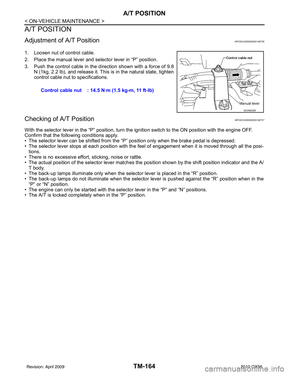
1. Loosen nut of control cable.
2. Place the manual lever and selector lever in “P” position.
3. Push the control cable in the direction shown with a force of 9.8
N (1kg, 2.2 lb), and release it. This is in the natural state, tighten
control cable nut to specifications.
Checking of A/T PositionINFOID:0000000005148737
With the selector lever in the “P” position, turn t he ignition switch to the ON position with the engine OFF.
Confirm that the following conditions apply.
• The selector lever can be shifted from the “P” position only when the brake pedal is depressed.
• The selector lever stops at each position with the f eel of engagement when it is moved through all the posi-
tions.
• There is no excessive effort, sticking, noise or rattle.
• The actual position of the selector lever matches the position shown by the shift position indicator and the A/
T body.
• The back-up lamps illuminate only when the selector lever is placed in the “R” position.
• The back-up lamps do not illuminate when the selector lever is pushed against the “R” position when in the “P” or “N” position.
• The engine can only be started with the select or lever in the “P” and “N” positions.
• The A/T is locked completely when in the “P” position. Control cable nut : 14.5 N·m (1.5 kg-m, 11 ft-lb)
SCIA6532E
Revision: April 20092010 QX56
Page 3881 of 4210
TM-186
< REMOVAL AND INSTALLATION >
TRANSMISSION ASSEMBLY
REMOVAL AND INSTALLATION
TRANSMISSION ASSEMBLY
Removal and Installation (2WD)INFOID:0000000005148743
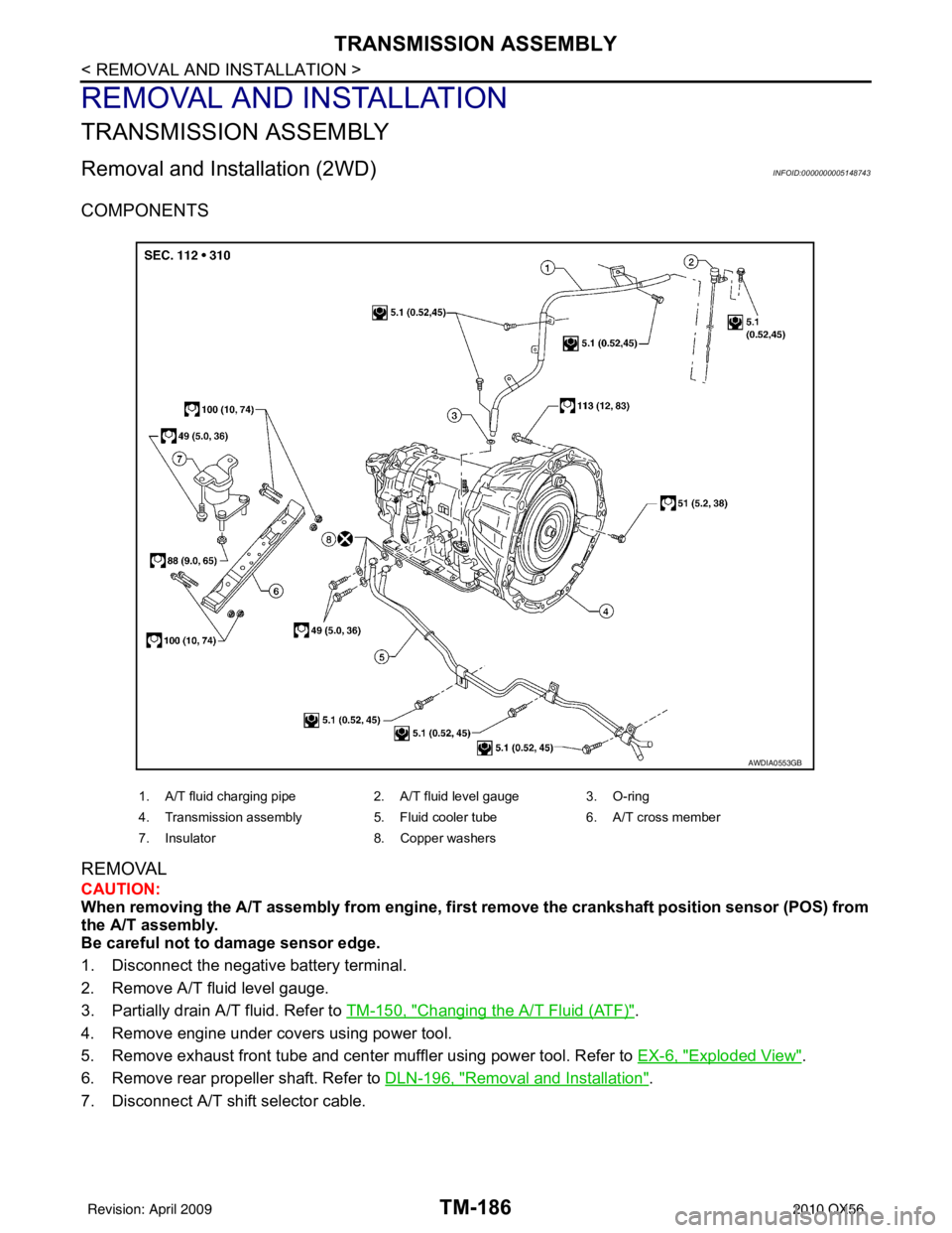
COMPONENTS
REMOVAL
CAUTION:
When removing the A/T assembly from engine, first remove the crankshaft position sensor (POS) from
the A/T assembly.
Be careful not to damage sensor edge.
1. Disconnect the negative battery terminal.
2. Remove A/T fluid level gauge.
3. Partially drain A/T fluid. Refer to TM-150, "
Changing the A/T Fluid (ATF)".
4. Remove engine under covers using power tool.
5. Remove exhaust front tube and center muffler using power tool. Refer to EX-6, "
Exploded View".
6. Remove rear propeller shaft. Refer to DLN-196, "
Removal and Installation".
7. Disconnect A/T shift selector cable.
1. A/T fluid charging pipe 2. A/T fluid level gauge 3. O-ring
4. Transmission assembly 5. Fluid cooler tube6. A/T cross member
7. Insulator 8. Copper washers
AWDIA0553GB
Revision: April 20092010 QX56
Page 3882 of 4210
TRANSMISSION ASSEMBLYTM-187
< REMOVAL AND INSTALLATION >
CEF
G H
I
J
K L
M A
B
TM
N
O P
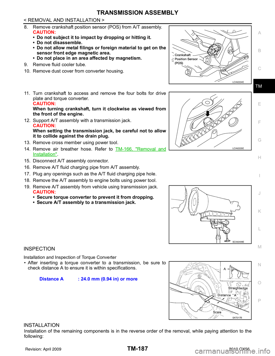
8. Remove crankshaft position sens or (POS) from A/T assembly.
CAUTION:
• Do not subject it to impact by dropping or hitting it.
• Do not disassemble.
• Do not allow metal filings or foreign material to get on the
sensor front edge magnetic area.
• Do not place in an area affected by magnetism.
9. Remove fluid cooler tube.
10. Remove dust cover from converter housing.
11. Turn crankshaft to access and remove the four bolts for drive plate and torque converter.
CAUTION:
When turning crankshaft, turn it clockwise as viewed from
the front of the engine.
12. Support A/T assembly with a transmission jack. CAUTION:
When setting the transmission jack, be careful not to allow
it to collide agai nst the drain plug.
13. Remove cross member using power tool.
14. Remove air breather hose. Refer to TM-166, "
Removal and
Installation".
15. Disconnect A/T assembly connector.
16. Remove A/T fluid charging pipe from A/T assembly.
17. Plug any openings such as the A/T fluid charging pipe hole.
18. Remove the A/T assembly to engine bolts using power tool.
19. Remove A/T assembly from vehicle using transmission jack. CAUTION:
• Secure torque converter to prevent it from dropping.
• Secure A/T assembly to a transmission jack.
INSPECTION
Installation and Inspection of Torque Converter
• After inserting a torque converter to a transmission, be sure to check distance A to ensure it is within specifications.
INSTALLATION
Installation of the remaining components is in the revers e order of the removal, while paying attention to the
following:
LCIA0334E
LCIA0335E
SCIA0499E
Distance A : 24.0 mm (0.94 in) or more
SAT017B
Revision: April 20092010 QX56
Page 3883 of 4210
TM-188
< REMOVAL AND INSTALLATION >
TRANSMISSION ASSEMBLY
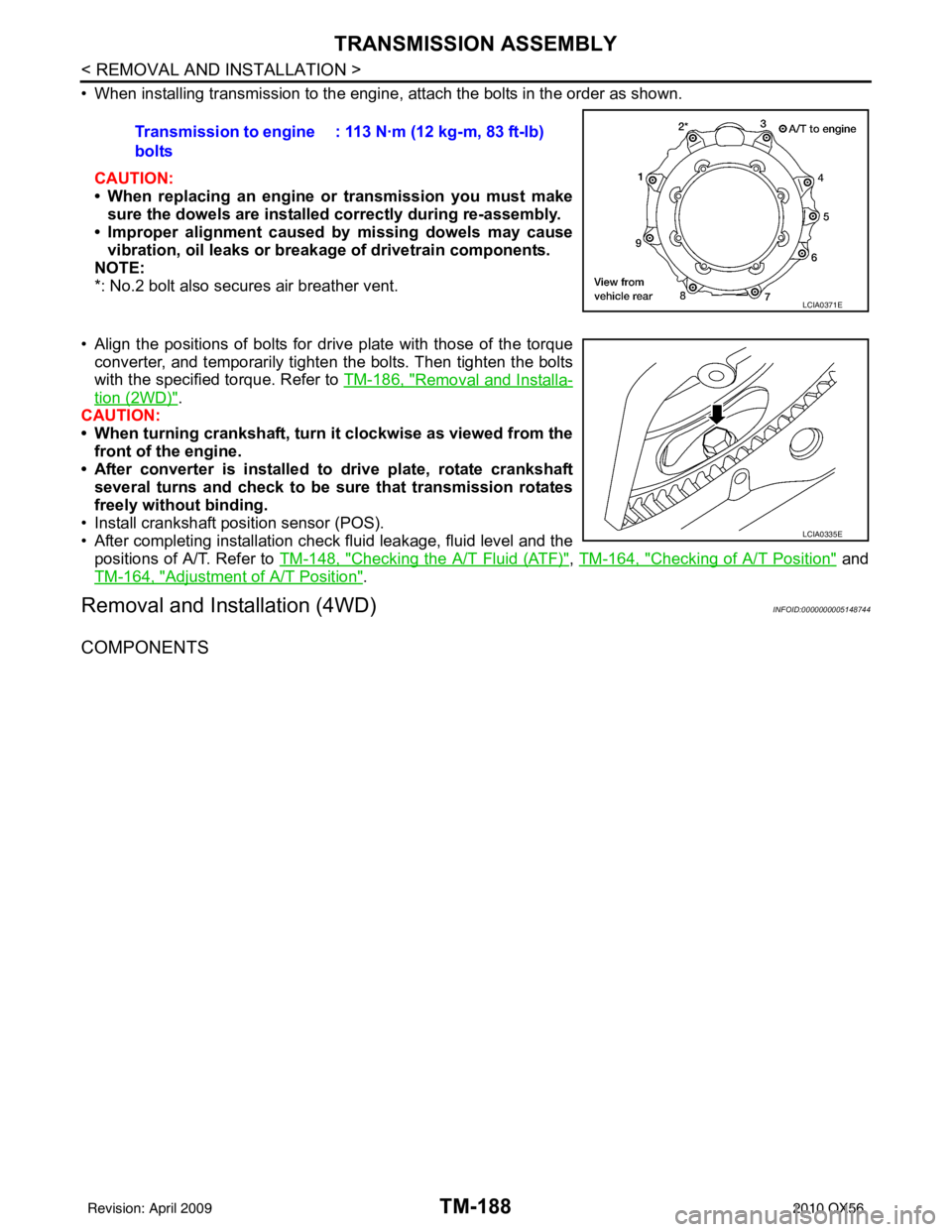
• When installing transmission to the engine, attach the bolts in the order as shown.CAUTION:
• When replacing an engine or transmission you must make
sure the dowels are installe d correctly during re-assembly.
• Improper alignment caused by missing dowels may cause
vibration, oil leaks or breakage of drivetrain components.
NOTE:
*: No.2 bolt also secures air breather vent.
• Align the positions of bolts for drive plate with those of the torque converter, and temporarily tighten the bolts. Then tighten the bolts
with the specified torque. Refer to TM-186, "
Removal and Installa-
tion (2WD)".
CAUTION:
• When turning crankshaft, turn it clockwise as viewed from the front of the engine.
• After converter is installed to drive plate, rotate crankshaft
several turns and check to be sure that transmission rotates
freely without binding.
• Install crankshaft pos ition sensor (POS).
• After completing installation check fluid leakage, fluid level and the
positions of A/T. Refer to TM-148, "
Checking the A/T Fluid (ATF)", TM-164, "Checking of A/T Position" and
TM-164, "
Adjustment of A/T Position".
Removal and Installation (4WD)INFOID:0000000005148744
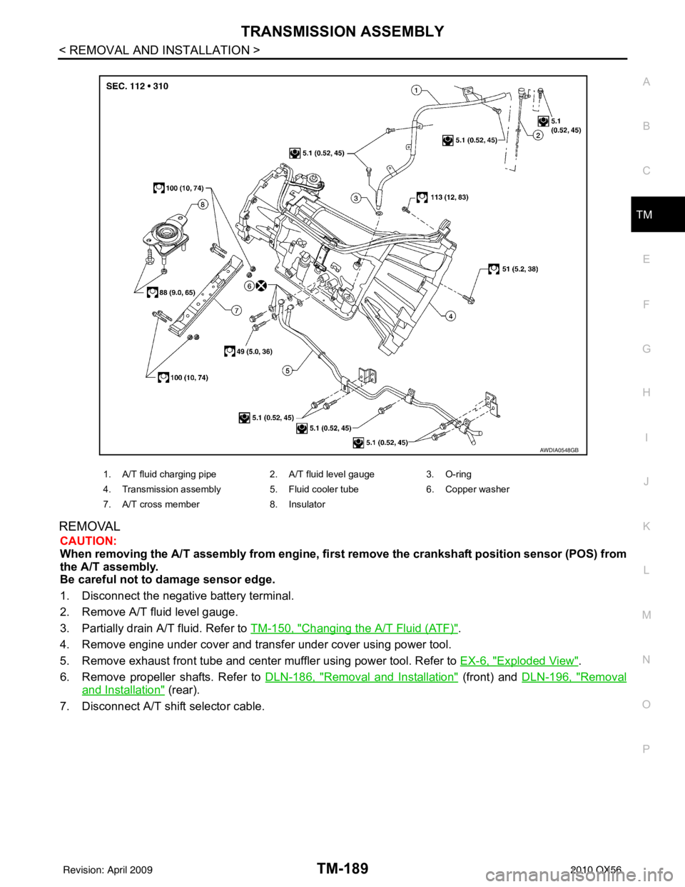
COMPONENTS
Transmission to engine
bolts : 113 N·m (12 kg-m, 83 ft-lb)
LCIA0371E
LCIA0335E
Revision: April 20092010 QX56
Page 3884 of 4210
TRANSMISSION ASSEMBLYTM-189
< REMOVAL AND INSTALLATION >
CEF
G H
I
J
K L
M A
B
TM
N
O P
REMOVAL
CAUTION:
When removing the A/T assembly from engine, firs t remove the crankshaft position sensor (POS) from
the A/T assembly.
Be careful not to damage sensor edge.
1. Disconnect the negative battery terminal.
2. Remove A/T fluid level gauge.
3. Partially drain A/T fluid. Refer to TM-150, "
Changing the A/T Fluid (ATF)".
4. Remove engine under cover and transfer under cover using power tool.
5. Remove exhaust front tube and center muffler using power tool. Refer to EX-6, "
Exploded View".
6. Remove propeller shafts. Refer to DLN-186, "
Removal and Installation" (front) and DLN-196, "Removal
and Installation" (rear).
7. Disconnect A/T shift selector cable.
1. A/T fluid charging pipe 2. A/T fluid level gauge3. O-ring
4. Transmission assembly 5. Fluid cooler tube6. Copper washer
7. A/T cross member 8. Insulator
AWDIA0548GB
Revision: April 20092010 QX56