2010 HYUNDAI TUCSON warning
[x] Cancel search: warningPage 333 of 382
745
Maintenance
5. Maximum permissible inflationpressure
This number is the greatest amount
of air pressure that should be put in
the tire. Do not exceed the maximum
permissible inflation pressure. Refer
to the Tire and Loading Information
label for recommended inflation
pressure.
6. Maximum load rating
This number indicates the maximum
load in kilograms and pounds that
can be carried by the tire. When
replacing the tires on the vehicle,
always use a tire that has the same
load rating as the factory installed
tire.
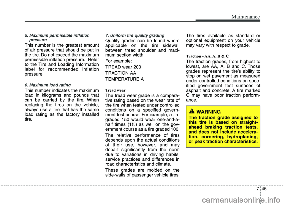
7. Uniform tire quality grading
Quality grades can be found where
applicable on the tire sidewall
between tread shoulder and maxi-
mum section width.
For example:
TREAD wear 200
TRACTION AA
TEMPERATURE A
Tread wear
The tread wear grade is a compara-
tive rating based on the wear rate of
the tire when tested under controlled
conditions on a specified govern-
ment test course. For example, a tire
graded 150 would wear one-and-a-
half times (1½) as well on the gov-
ernment course as a tire graded 100.
The relative performance of tires
depends upon the actual conditions
of their use, however, and may
depart significantly from the norm
due to variations in driving habits,
service practices and differences in
road characteristics and climate.
These grades are molded on the
side-walls of passenger vehicle tires. The tires available as standard or
optional equipment on your vehicle
may vary with respect to grade.
Traction - AA, A, B & C
The traction grades, from highest to
lowest, are AA, A, B and C. Those
grades represent the tire’s ability to
stop on wet pavement as measured
under controlled conditions on spec-
ified government test surfaces of
asphalt and concrete. A tire marked
C may have poor traction perform-
ance.
WARNING
The traction grade assigned to
this tire is based on straight-
ahead braking traction tests,
and does not include accelera-
tion, cornering, hydroplaning,
or peak traction characteristics.
Page 334 of 382
Maintenance
46
7
Temperature -A, B & C
The temperature grades are A (the
highest), B and C representing the
tire’s resistance to the generation of
heat and its ability to dissipate heat
when tested under controlled condi-
tions on a specified indoor laboratory
test wheel.
Sustained high temperature can
cause the material of the tire to
degenerate and reduce tire life, and
excessive temperature can lead to
sudden tire failure. The grade C cor-
responds to a level of performance
which all passenger car tires must
meet under the Federal Motor
Vehicle Safety Standard No. 109.
Grades B and A represent higher
levels of performance on the labora-
tory test wheel than the minimum
required by law. Tire terminology and definitions
Air Pressure
: The amount of air
inside the tire pressing outward on
the tire. Air pressure is expressed in
pounds per square inch (psi) or kilo-
pascal (kPa).
Accessory Weight : This means the
combined weight of optional acces-
sories. Some examples of optional
accessories are, automatic transaxle,
power seats, and air conditioning.
Aspect Ratio : The relationship of a
tire's height to its width.
Belt: A rubber coated layer of cords
that is located between the plies and
the tread. Cords may be made from
steel or other reinforcing materials.
Bead : The tire bead contains steel
wires wrapped by steel cords that
hold the tire onto the rim.
Bias Ply Tire : A pneumatic tire in
which the plies are laid at alternate
angles less than 90 degrees to the
centerline of the tread.WARNING - Tire temperature
The temperature grade for this
tire is established for a tire that
is properly inflated and not
overloaded. Excessive speed,
underinflation, or excessive
loading, either separately or in
combination, can cause heat
build-up and possible sudden
tire failure. This can cause loss
of vehicle control and serious
injury or death.
Page 337 of 382
749
Maintenance
Do not drive faster than 75 mph (120
km/h) when your vehicle is equipped
with snow tires.
Tire chains
Tire chains, if necessary, should be
installed on the drive wheels as fol-
lows.
2WD : Front wheels
AWD : All four wheelsIf a full set of chains is not
available for a AWD vehicle,
chains may be installed on
the front wheels only.
Be sure that the chains are installed
in accordance with the manufactur-
er's instructions.
To minimize tire and chain wear, do
not continue to use tire chains when
they are no longer needed.Radial-ply tires
Radial-ply tires provide improved
tread life, road hazard resistance and
smoother high speed ride. The radi-
al-ply tires used on this vehicle are of
belted construction, and are selected
to complement the ride and handling
characteristics of your vehicle.
Radial-ply tires have the same load
carrying capacity, as bias-ply or bias
belted tires of the same size, and use
the same recommended inflation
pressure. Mixing of radial-ply tires
with bias-ply or bias belted tires is
not recommended. Any combina-
tions of radial-ply and bias-ply or bias
belted tires when used on the same
vehicle will seriously deteriorate
vehicle handling. The best rule to fol-
low is: Identical radial-ply tires should
always be used as a set of four.
Longer wearing tires can be more
susceptible to irregular tread wear. It
is very important to follow the tire
rotation interval shown in this section
to achieve the tread life potential of
these tires. Cuts and punctures in
radial-ply tires are repairable only in
the tread area, because of sidewall
flexing. Consult your tire dealer for
radial-ply tire repairs.WARNING- Snow or ice
When driving on roads cov- ered with snow or ice, drive at
less than 20 mph (30 km/h).
Use the SAE “S” class or wire chains.
If you hear noise caused by chains contacting the body,
retighten the chain to avoid
contact with the vehicle body.
To prevent body damage, retighten the chains after driv-
ing 0.3~0.6 miles (0.5~1.0 km).
Do not use tire chains on vehicles equipped with alu-
minum wheels. In unavoid-
able circumstance, use a wire
type chain.
Use wire chains less than 0.59 inches (15 mm) to prevent
damage to the chain’s con-
nection.
Page 338 of 382
Maintenance
50
7
FUSES
A vehicle’s electrical system is protected
from electrical overload damage by
fuses.
This vehicle has 3 fuse panels, one locat-
ed in the driver’s side panel bolster, the
other in the engine compartment.
If any of your vehicle’s lights, acces-
sories, or controls do not work, check the
appropriate circuit fuse. If a fuse has
blown, the element inside the fuse will
melt.
If the electrical system does not work,
first check the driver’s side fuse panel.
Always replace a blown fuse with one of
the same rating.
If the replacement fuse blows, this indi-
cates an electrical problem. Avoid using
the system involved and immediately
consult an authorized HYUNDAI dealer.
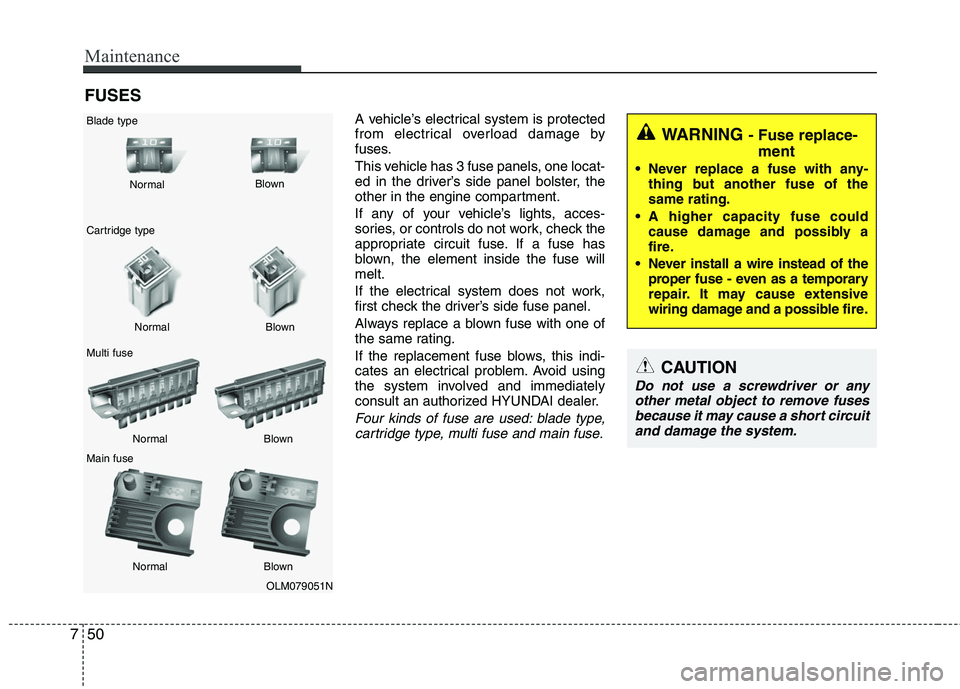
Four kinds of fuse are used: blade type,
cartridge type, multi fuse and main fuse.
WARNING - Fuse replace- ment
Never replace a fuse with any-
thing but another fuse of the
same rating.
A higher capacity fuse could cause damage and possibly a
fire.
Never install a wire instead of the proper fuse - even as a temporary
repair. It may cause extensive
wiring damage and a possible fire.
CAUTION
Do not use a screwdriver or any
other metal object to remove fuses because it may cause a short circuitand damage the system.
OLM079051N
Normal
Normal
Blade type
Cartridge type
Multi fuse
Main fuse Blown
Blown
Normal Blown
Normal Blown
Page 340 of 382
Maintenance
52
7
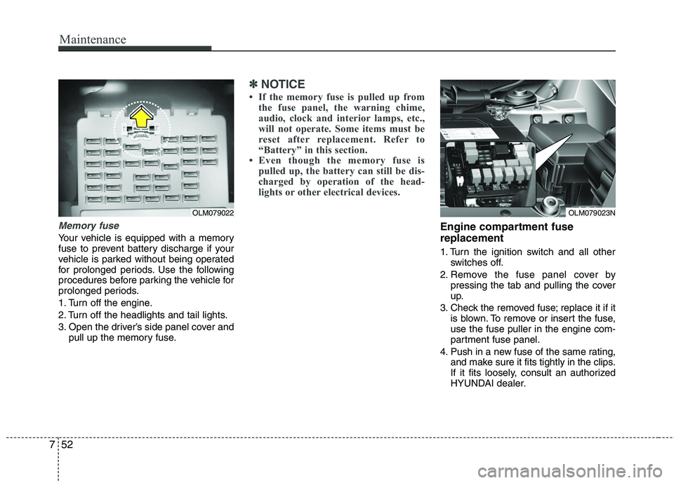
Memory fuse
Your vehicle is equipped with a memory
fuse to prevent battery discharge if your
vehicle is parked without being operated
for prolonged periods. Use the following
procedures before parking the vehicle for
prolonged periods.
1. Turn off the engine.
2. Turn off the headlights and tail lights.
3. Open the driver’s side panel cover and
pull up the memory fuse.
✽ ✽NOTICE
• If the memory fuse is pulled up from
the fuse panel, the warning chime,
audio, clock and interior lamps, etc.,
will not operate. Some items must be
reset after replacement. Refer to
“Battery” in this section.
• Even though the memory fuse is pulled up, the battery can still be dis-
charged by operation of the head-
lights or other electrical devices.
Engine compartment fuse
replacement
1. Turn the ignition switch and all other
switches off.
2. Remove the fuse panel cover by pressing the tab and pulling the cover
up.
3. Check the removed fuse; replace it if it is blown. To remove or insert the fuse,
use the fuse puller in the engine com-
partment fuse panel.
4. Push in a new fuse of the same rating, and make sure it fits tightly in the clips.
If it fits loosely, consult an authorized
HYUNDAI dealer.
OLM079023N
OLM079022
Page 343 of 382
755
Maintenance
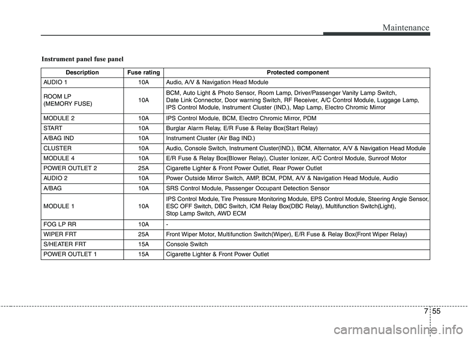
Instrument panel fuse panel
Description Fuse rating Protected component
AUDIO 1 10A Audio, A/V & Navigation Head Module
ROOM LP
(MEMORY FUSE) 10ABCM, Auto Light & Photo Sensor, Room Lamp, Driver/Passenger Vanity Lamp Switch,
Date Link Connector, Door warning Switch, RF Receiver, A/C Control Module, Luggage Lamp,
IPS Control Module, Instrument Cluster (IND.), Map Lamp, Electro Chromic Mirror
MODULE 2 10A IPS Control Module, BCM, Electro Chromic Mirror, PDM
START 10A Burglar Alarm Relay, E/R Fuse & Relay Box(Start Relay)
A/BAG IND 10A Instrument Cluster (Air Bag IND.)
CLUSTER 10A Audio, Console Switch, Instrument Cluster(IND.), BCM, Alternator, A/V & Navigation Head Module
MODULE 4 10A E/R Fuse & Relay Box(Blower Relay), Cluster Ionizer, A/C Control Module, Sunroof Motor
POWER OUTLET 2 25A Cigarette Lighter & Front Power Outlet, Rear Power Outlet
AUDIO 2 10A Power Outside Mirror Switch, AMP, BCM, PDM, A/V & Navigation Head Module, Audio
A/BAG 10A SRS Control Module, Passenger Occupant Detection Sensor
MODULE 1 10A IPS
Control Module, Tire Pressure Monitoring Module, EPS ControlModule, Steering Angle Sensor,
ESC OFF Switch, DBC Switch, ICM Relay Box(DBC Relay), Multifunction Switch(Light),
Stop Lamp Switch, AWD ECM
FOG LP RR 10A -
WIPER FRT 25A Front Wiper Motor, Multifunction Switch(Wiper), E/R Fuse & Relay Box(Front Wiper Relay)
S/HEATER FRT 15A Console Switch
POWER OUTLET 1 15A Cigarette Lighter & Front Power Outlet
Page 347 of 382
759
Maintenance
LIGHT BULBS
Use only the bulbs of the specifiedwattage.
✽
✽ NOTICE
After heavy, driving rain or washing,
headlight and taillight lenses could
appear frosty. This condition is caused by
the temperature difference between the
lamp inside and outside. This is similar
to the condensation on your windows
inside your vehicle during the rain and
doesn’t indicate a problem with your
vehicle. If the water leaks into the lamp
bulb circuitry, have the vehicle checked
by an authorized HYUNDAI dealer.
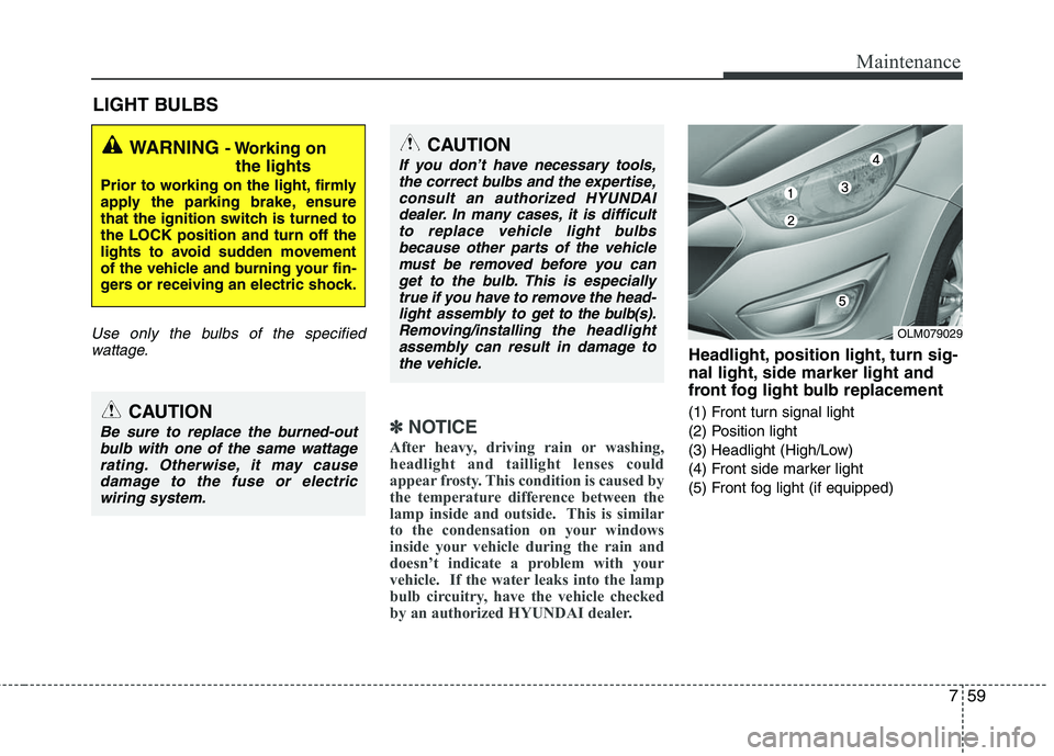
Headlight, position light, turn sig-
nal light, side marker light and
front fog light bulb replacement
(1) Front turn signal light
(2) Position light
(3) Headlight (High/Low)
(4) Front side marker light
(5) Front fog light (if equipped)
WARNING - Working on
the lights
Prior to working on the light, firmly
apply the parking brake, ensure
that the ignition switch is turned to
the LOCK position and turn off the
lights to avoid sudden movement
of the vehicle and burning your fin-
gers or receiving an electric shock.
CAUTION
Be sure to replace the burned-out
bulb with one of the same wattagerating. Otherwise, it may causedamage to the fuse or electric wiring system.
CAUTION
If you don’t have necessary tools,the correct bulbs and the expertise,consult an authorized HYUNDAIdealer. In many cases, it is difficultto replace vehicle light bulbsbecause other parts of the vehicle must be removed before you canget to the bulb. This is especiallytrue if you have to remove the head-light assembly to
get to the bulb(s).
Removing/installingthe headlight
assembly can result in damage to the vehicle.
OLM079029
Page 348 of 382
Maintenance
60
7
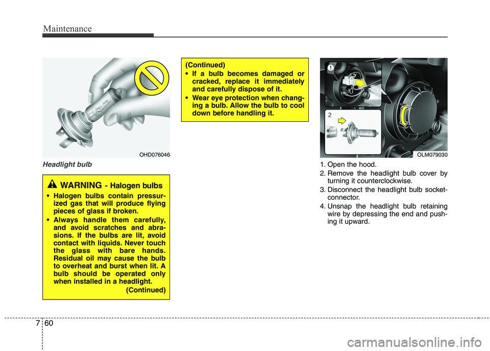
Headlight bulb1. Open the hood.
2. Remove the headlight bulb cover by
turning it counterclockwise.
3. Disconnect the headlight bulb socket- connector.
4. Unsnap the headlight bulb retaining wire by depressing the end and push-
ing it upward.
(Continued)
If a bulb becomes damaged orcracked, replace it immediately
and carefully dispose of it.
Wear eye protection when chang- ing a bulb. Allow the bulb to cool
down before handling it.
OHD076046
WARNING- Halogen bulbs
Halogen bulbs contain pressur-ized gas that will produce flying
pieces of glass if broken.
Always handle them carefully, and avoid scratches and abra-
sions. If the bulbs are lit, avoid
contact with liquids. Never touch
the glass with bare hands.
Residual oil may cause the bulb
to overheat and burst when lit. A
bulb should be operated only
when installed in a headlight.
(Continued)
OLM079030