2010 Hyundai Sonata ignition
[x] Cancel search: ignitionPage 197 of 285
316
WHAT TO DO IN AN EMERGENCY
CAUTION:
o When towing the vehicle, take care
not to cause damage to the bumper or
underbody of the vehicle.
!
NOTE:Before towing, check the level of the
automatic transaxle fluid. If it is below
the "HOT" range on the dipstick, add
fluid. If you cannot add fluid, a towing
dolly must be used.
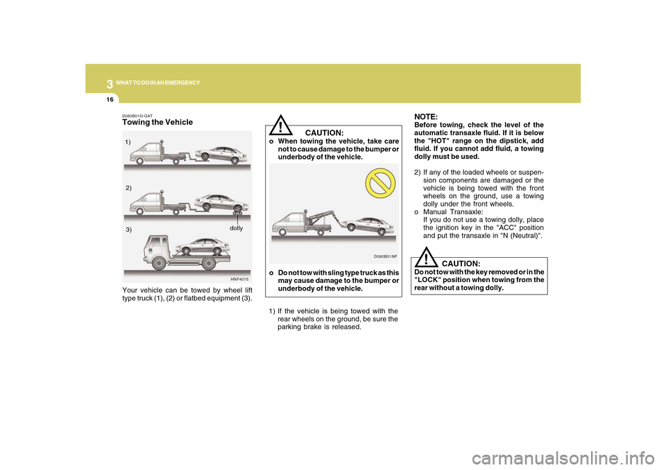
2) If any of the loaded wheels or suspen-
sion components are damaged or the
vehicle is being towed with the front
wheels on the ground, use a towing
dolly under the front wheels.
o Manual Transaxle:
If you do not use a towing dolly, place
the ignition key in the "ACC" position
and put the transaxle in "N (Neutral)".
CAUTION:
Do not tow with the key removed or in the
"LOCK" position when towing from the
rear without a towing dolly.
D080B01NF
!
o Do not tow with sling type truck as this
may cause damage to the bumper or
underbody of the vehicle.
1) If the vehicle is being towed with the
rear wheels on the ground, be sure the
parking brake is released.
D080B01O-GATTowing the Vehicle
HNF4015
Your vehicle can be towed by wheel lift
type truck (1), (2) or flatbed equipment (3).1)
2)
3)
dolly
Page 237 of 285

6
DO-IT-YOURSELF MAINTENANCE
23
!
CAUTION:
When replacing a fusible link, never use
anything but a new fusible link with the
same or lower amperage rating. Never
use a piece of wire or a higher-rated
fusible link. This could result in serious
damage and create a fire hazard.
G200B02NF
4. Replace the blown fuse by pressing a
new fuse of the same rating into place.
The fuse should be a snug fit. If it is not,
have the fuse clip repaired or replaced
by a Hyundai dealer. If you do not have
a spare fuse, you may be able to borrow
a fuse of the same or lower rating from
an accessory you can temporarily get
along without (the radio or cigarette
lighter, for example). Always remember
to replace the borrowed fuse.
G200B01NF-AATReplacing Accessory FuseThe fuse box for the lights and other elec-
trical accessories will be found on the left
side of the instrument panel. Inside the box
you will find a list showing the circuits
protected by each fuse.
If any of your car's lights or other electrical
accessories stop working, a blown fuse
could be the reason. If the fuse has burned
out, you will see that the metal strip inside
the fuse has burned through. If you suspect
a blown fuse, follow this procedure:
1. Turn off the ignition and all other
switches.
2. Open the fuse box and examine each
fuse. Remove each fuse by pulling it
toward you (a small "fuse puller" tool is
contained in the relay and fuse box of
the engine room to simplify this
operation).
ONF078018
3. Be sure to check all other fuses, even if
you find one that appears to have burned
out.
Page 239 of 285
6
DO-IT-YOURSELF MAINTENANCE
25
!
G210B01NF-AATChecking the BatteryKeep the battery clean. Any evidence of
corrosion around the battery posts or
terminals should be removed using a
solution of household baking soda and
warm water. After the battery terminals are
dry, cover them with a light coating of
grease.
PROPOSITION 65 WARNING:
Battery posts, terminals, and related
accessories contain lead and lead com-
pounds, chemicals known to the State of
California to cause cancer, birth defects
and reproductive harm. Batteries also
contain other chemicals known to the
State of California to cause cancer. Wash
hands after handling.
!
!
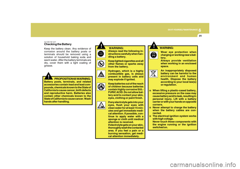
WARNING:Always read the following in-
structions carefully when han-
dling a battery.
Keep lighted cigarettes and all
other flames or sparks away
from the battery.
Hydrogen, which is a highly
combustible gas, is always
present in battery cells and
may explode if ignited.
Keep batteries out of the reach
of children because batteries
contain highly corrosive SUL-
FURIC ACID. Do not allow bat-
tery acid to contact your skin,
eyes, clothing or paint finish.
If any electrolyte gets into your
eyes, flush your eyes with
clean water for at least 15 min-
utes and get immediate medi-
cal attention. If possible, con-
tinue to apply water with a
sponge or cloth until medical
attention is received.
If electrolyte gets on your skin,
thoroughly wash the contacted
area. If you feel a pain or a
burning sensation, get medi-
cal attention immediately.Wear eye protection when
charging or working near a bat-
tery.
Always provide ventilation
when working in an enclosed
space.
An inappropriately disposed
battery can be harmful to the
environment and human
health. Dispose the battery
according to your local law(s)
or regulation.
o When lifting a plastic-cased battery,
excessive pressure on the case may
cause battery acid to leak, resulting in
personal injury. Lift with a battery
carrier or with your hands on opposite
corners.
o Never attempt to charge the battery
when the battery cables are con-
nected.
o The electrical ignition system works
with high voltage.
Never touch these components with
the engine running or the ignition
switched on.
WARNING:
Page 252 of 285
6
DO-IT-YOURSELF MAINTENANCE
38
1
2
3
4
5
6
7
8
9
10
11
12
13
14
15
16
17
18
19
20
21
22
23
24
HORN
TAIL
ECU
IG1
DRL
FR FOG
A/CON
F/PUMP
DIODE
ATM
STOP
H/LP LO RH
S/ROOF
H/LP WASHER
H/LP HI
ECU
SNSR.3
SNSR.1
SNSR.2
B/UP
IGN COIL
ECU (IG1)
H/LP LO
ABS
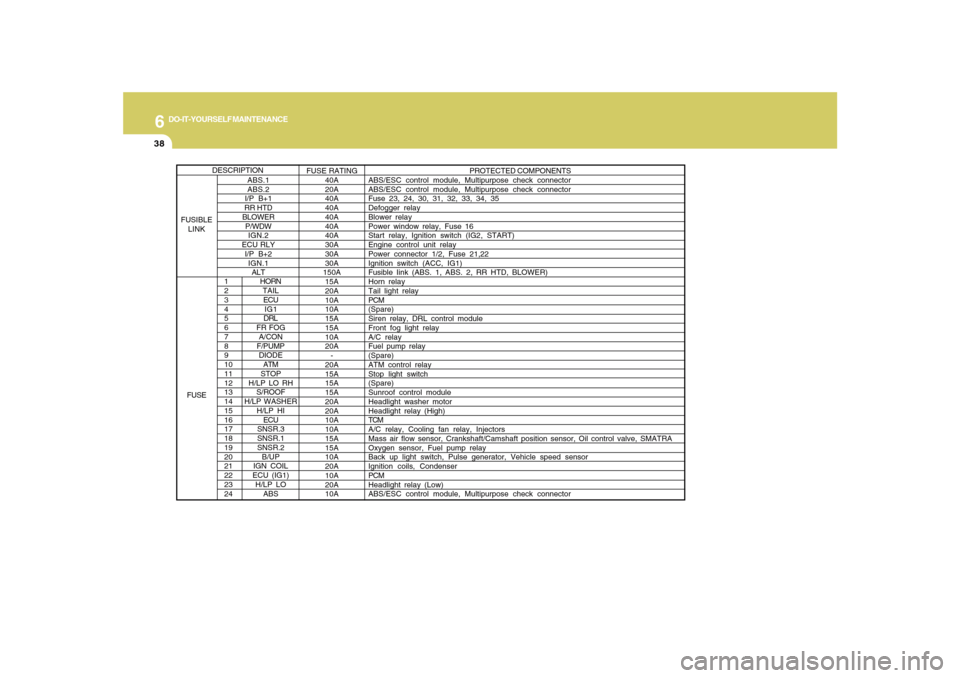
PROTECTED COMPONENTS
ABS/ESC control module, Multipurpose check connector
ABS/ESC control module, Multipurpose check connector
Fuse 23, 24, 30, 31, 32, 33, 34, 35
Defogger relay
Blower relay
Power window relay, Fuse 16
Start relay, Ignition switch (IG2, START)
Engine control unit relay
Power connector 1/2, Fuse 21,22
Ignition switch (ACC, IG1)
Fusible Iink (ABS. 1, ABS. 2, RR HTD, BLOWER)
Horn relay
Tail light relay
PCM
(Spare)
Siren relay, DRL control module
Front fog light relay
A/C relay
Fuel pump relay
(Spare)
ATM control relay
Stop light switch
(Spare)
Sunroof control module
Headlight washer motor
Headlight relay (High)
TCM
A/C relay, Cooling fan relay, Injectors
Mass air flow sensor, Crankshaft/Camshaft position sensor, Oil control valve, SMATRA
Oxygen sensor, Fuel pump relay
Back up light switch, Pulse generator, Vehicle speed sensor
Ignition coils, Condenser
PCM
Headlight relay (Low)
ABS/ESC control module, Multipurpose check connector
ABS.1
ABS.2
I/P B+1
RR HTD
BLOWER
P/WDW
IGN.2
ECU RLY
I/P B+2
IGN.1
ALTFUSE RATING
40A
20A
40A
40A
40A
40A
40A
30A
30A
30A
150A
15A
20A
10A
10A
15A
15A
10A
20A
-
20A
15A
15A
15A
20A
20A
10A
10A
15A
15A
10A
20A
10A
20A
10A
DESCRIPTION
FUSIBLE
LINK
FUSE
Page 258 of 285
7
EMISSION CONTROL SYSTEMS4
!
WARNING:
!
WARNING:
o Your vehicle is designed to operate
with a catalytic converter and remov-
ing it will cause the engine to operate
poorly and fuel economy to drop along
with an increase in the vehicle emis-
sions.
o Remember that your Hyundai dealer
is your best source of assistance.
o Do not park, idle or drive your vehicle
over or near flammable objects such
as grass, paper, leaves or rags. These
materials might contact the hot cata-
lytic converter and a fire might result. o Use unleaded fuel only.
o Maintain the engine in good operating
condition. Extremely high catalytic
converter temperatures can result
from improper operation of the
electrical, ignition or multiport
electronic fuel injection.
o If your engine stalls, pings, knocks, or
is hard to start, have your Hyundai
dealer inspect and repair the problem
as soon as possible.
o Avoid driving with a very low fuel level.
Running out of gasoline may cause
the engine to misfire and result in
damage to the catalytic converter.
o Avoid idling the engine for periods
longer than 10 minutes.
o The vehicle should not be pushed or
pulled to get started. This may cause
the catalytic converter to overheat
and create a fire hazard.
o Do not touch the catalytic converter
or any other part of the exhaust system
while the catalytic converter is hot.
Shut off the engine, wait for at least
one hour before touching the cata-
lytic converter or any other part of the
exhaust system.
Page 278 of 285
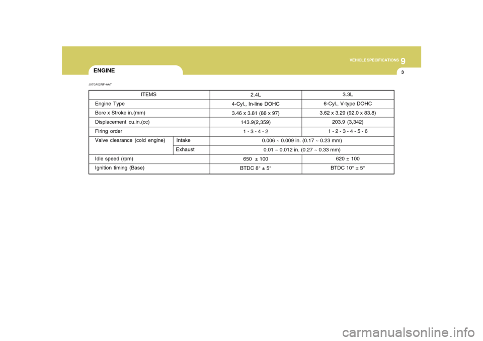
9
VEHICLE SPECIFICATIONS
3
3.3L
6-Cyl., V-type DOHC
3.62 x 3.29 (92.0 x 83.8)
203.9 (3,342)
1 - 2 - 3 - 4 - 5 - 6
620 ± 100
BTDC 10° ± 5° 0.006 ~ 0.009 in. (0.17 ~ 0.23 mm)
0.01 ~ 0.012 in. (0.27 ~ 0.33 mm) 2.4L
4-Cyl., In-line DOHC
3.46 x 3.81 (88 x 97)
143.9(2,359)
1 - 3 - 4 - 2
650 ± 100
BTDC 8° ± 5°
ENGINEJ070A02NF-AAT
ITEMS
Engine Type
Bore x Stroke in.(mm)
Displacement cu.in.(cc)
Firing order
Valve clearance (cold engine) Intake
Exhaust
Idle speed (rpm)
Ignition timing (Base)
Page 283 of 285

10
INDEX
4
Fuel
Capacity............................................................................ 9-2
Gauge..............................................................................1-58
Recommendations............................................................ 1-2
Fuel Filler Lid
Remote release ..............................................................1-87
Fuse Panel Description .....................................................6-37
Fuses..................................................................................6-22
G
General Checks ................................................................... 6-4
Glove Box ...........................................................................1-76
H
Hazard Warning System ....................................................1-68
Headlight
Aiming adjustment ..........................................................6-27
Replacement...................................................................6-28
Switch..............................................................................1-64
Heating and Ventilation
Air flow control ................................................... 1-97, 1-108
Air intake control switch ..................................... 1-99, 1-107
Bi-level heating .............................................................1-100
Defrosting/Defogging....................................................1-103
Fan speed control (Blower Control) .................. 1-97, 1-107
Temperature control .......................................................1-96
High-Mounted Rear Stop Light .........................................1-87
Hood Release ....................................................................1-89
Horn....................................................................................1-91I
Ignition Switch ...................................................................... 2-3
Instrument Cluster and Indicator Lights ............................1-50
Instrument Panel Light Control (Rheostat) .......................1-69
Interior Light .......................................................................1-74
Intermittent Wiper ...............................................................1-67
J
Jump Starting ....................................................................... 3-3
K
Key ........................................................................................ 1-3
If you lose your keys ......................................................3-17
Positions............................................................................ 2-3
L
Light Bulb Watages ............................................................6-36
Light Bulbs Replacement ..................................................6-28
Lubrication Chart .................................................................. 9-4
M
Maintenance Intervals
Explanation of scheduled maintenance items ................ 5-7
Maintenance under severe usage conditions ................. 5-6
Scheduled maintenance.................................................. 5-4
Service requirements ........................................................ 5-2
Manual Heating and Cooling Control System ..................1-96