2010 Hyundai Sonata warning lights
[x] Cancel search: warning lightsPage 81 of 285

1FEATURES OF YOUR HYUNDAI68
ONF048071NONF048072
NOTE:The engine must be running for the rear
window defroster to operate.
CAUTION:
Do not clean the inner side of the rear
window glass with an abrasive type of
glass cleaner or use a scraper to remove
foreign deposits from the inner surface
of the glass as this may cause damage
to the defroster elements.
!
B380A02NF-AATThe rear window defroster switch also
activates the outside rearview mirror
heaters.
The rear window defroster and heated
outside rearview mirrors are turned on by
pushing in the switch. To turn the defroster
off, push the switch a second time. The rear
window defroster automatically turns itself
off after about 20 minutes. To restart the
defroster cycle, push in the switch again
after it has turned itself off.REAR WINDOW DEFROSTER
SWITCHWith Manual A/C
With Automatic A/C
HAZARD WARNING SYSTEMB370A01A-AATThe hazard warning system should be
used whenever you find it necessary to
stop the car in a hazardous location. When
you must make such an emergency stop,
always pull off the road as far as possible.
The hazard warning lights are turned on by
pushing in the hazard switch. This causes
all turn signal lights to blink. The hazard
warning lights will operate even though
the key is not in the ignition.
To turn the hazard warning lights off, push
the switch a second time.
ONF048057
Page 100 of 285
1
FEATURES OF YOUR HYUNDAI
87
HIGH-MOUNTED REAR STOP
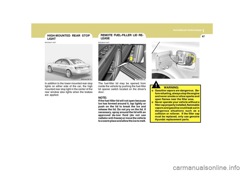
LIGHTB550A02Y-AATIn addition to the lower-mounted rear stop
lights on either side of the car, the high
mounted rear stop light in the center of the
rear window also lights when the brakes
are applied.
B550A01NF-A
REMOTE FUEL-FILLER LID RE-
LEASEB560A04Y-AATThe fuel-filler lid may be opened from
inside the vehicle by pushing the fuel-filler
lid opener switch located on the driver's
door.NOTE:If the fuel-filler lid will not open because
ice has formed around it, tap lightly or
push on the lid to break the ice and
release the lid. Do not pry on the lid. If
necessary, spray around the lid with an
approved de-icer fluid (do not use
radiator anti-freeze) or move the vehicle
to a warm place and allow the ice to melt.
ONF048018L
!
WARNING:
o Gasoline vapors are dangerous. Be-
fore refueling, always stop the engine
and never smoke or allow sparks and
open flames near the filler area.
o Never operate your vehicle without a
filler cap properly installed, flammable
vapors and gasoline could leak out in
dangerous situations such as a
collision or rollover. If the filler cap
must be replaced, only use genuine
Hyundai replacement parts.
HNF2021
Page 156 of 285
2
DRIVING YOUR HYUNDAI
3
!
BEFORE STARTING
THE ENGINEC020A01NF-AATBefore you start the engine, you should
always:
1. Look around the vehicle to be sure
there are no flat tires, puddles of oil,
water or other indications of possible
trouble.
2. After entering the car, check to be sure
the parking brake is engaged.
3. Check that all windows and lights are
clean.
4. Check that the interior and exterior
mirrors are clean and in position.
5. Check your seat, seatback and head-
rest to be sure they are in their proper
positions.
6. Lock all the doors.
7. Fasten your seat belt and be sure that all
other occupants have fastened theirs.
8. Turn off all lights and accessories that
are not needed.
9. When you turn the ignition switch to
"ON", check that all appropriate warning
lights are operating and that you have
sufficient fuel.
10. Check the operation of warning lights
and all bulbs when key is in the "ON"
position.
TO START THE ENGINEC030A01E-AATCOMBINATION IGNITION SWITCHo If your Hyundai is equipped with a
manual transaxle, place the shift lever
in neutral and depress the clutch pedal
fully.
o If your Hyundai has an automatic
transaxle, place the shift lever in "P"
(Park).
o To start the engine, insert the ignition
key and turn it to the "START" position.
Release it as soon as the engine starts.
Do not hold the key in the "START"
position for more than 15 seconds.NOTE:o For safety, the engine will not start if
the clutch pedal is not depressed fully
(Manual Transaxle) or the shift lever
is not in "P" or "N" Position (Automatic
Transaxle).
o The ignition key cannot be turned from
"ACC" position to "LOCK" position
unless the shift lever is in the "P"
(Park) position or the negative battery
terminal is disconnected from the bat-
tery. To remove the key, always
confirm that the shift lever is securely
positioned in "P" (Park) (For Automatic
Transaxle).
o For additional information about start-
ing, see page 2-5.
WARNING:
o All passengers must be properly
belted whenever the vehicle is moving.
Refer to pages: 1-22 through 1-34 for
more information on their proper use.
o Always check the surrounding areas
near your vehicle for people,
especially children, before putting a
car into 'drive'.
!
WARNING:
Always wear appropriate shoes when
operating your vehicle.
Unsuitable shoes (high heels, ski boots,
etc.) may interfere with your ability to
use the brake and accelerator pedal,
and the clutch (if installed).
!
WARNING:
When you intend to park or stop the
vehicle with the engine on, be careful not
to depress the accelerator pedal for a
long period of time. It may overheat the
engine or exhaust system and cause
fire.
Page 158 of 285
2
DRIVING YOUR HYUNDAI
5
!
STARTING!
C050A01A-AAT
WARNING:
Never run the engine in a closed or poorly
ventilated area any longer than is needed
to move your car in or out of the area. The
carbon monoxide gas emitted is odorless
and can cause serious injury or death.
C050A01E
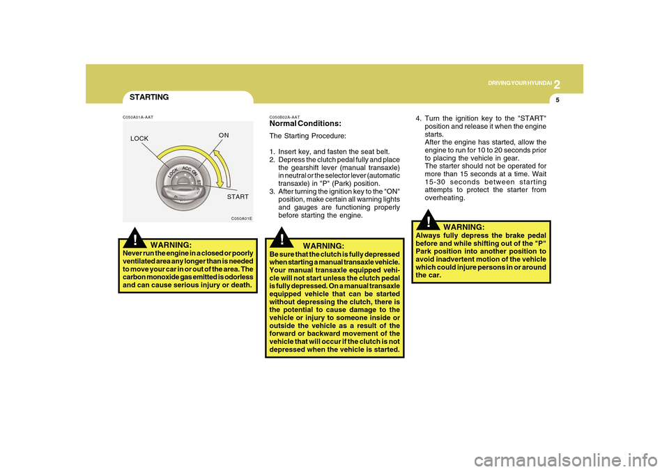
4. Turn the ignition key to the "START"
position and release it when the engine
starts.
After the engine has started, allow the
engine to run for 10 to 20 seconds prior
to placing the vehicle in gear.
The starter should not be operated for
more than 15 seconds at a time. Wait
15-30 seconds between starting
attempts to protect the starter from
overheating.
C050B02A-AATNormal Conditions:The Starting Procedure:
1. Insert key, and fasten the seat belt.
2. Depress the clutch pedal fully and place
the gearshift lever (manual transaxle)
in neutral or the selector lever (automatic
transaxle) in "P" (Park) position.
3. After turning the ignition key to the "ON"
position, make certain all warning lights
and gauges are functioning properly
before starting the engine.
WARNING:
Be sure that the clutch is fully depressed
when starting a manual transaxle vehicle.
Your manual transaxle equipped vehi-
cle will not start unless the clutch pedal
is fully depressed. On a manual transaxle
equipped vehicle that can be started
without depressing the clutch, there is
the potential to cause damage to the
vehicle or injury to someone inside or
outside the vehicle as a result of the
forward or backward movement of the
vehicle that will occur if the clutch is not
depressed when the vehicle is started.
!
WARNING:
Always fully depress the brake pedal
before and while shifting out of the "P"
Park position into another position to
avoid inadvertent motion of the vehicle
which could injure persons in or around
the car.
LOCKON
START
Page 175 of 285
2
DRIVING YOUR HYUNDAI
22
C190F01Y-GATTrailer or Vehicle Towing Tips1. Before towing, check hitch and safety
chain connections as well as proper
operation of the trailer running lights,
brake lights, and turn signals.
2. Always drive your vehicle at a moderate
speed. (Less than 60 mph)
3. Trailer towing requires more fuel than
normal conditions.
4. To maintain engine braking efficiency
and electrical charging performance,
do not tow a trailer with the transaxle in
fifth gear (manual transaxle).
5. Always secure items in the trailer to
prevent load shift while driving.
6. Check the condition and air pressure of
all tires on the trailer and your car. Low
tire pressure can seriously affect the
handling. Also check the spare tire.
7. The vehicle/trailer combination is more
affected by crosswind and buffeting.
When being passed by a large vehicle,
keep a constant speed and steer straight
ahead. If there is too much wind
buffeting, slow down to get out of the
other vehicle's air turbulence.
!
lbs(kg)
!
Tongue
100 (45)
- With3.3L
Brake 2.4L
Without BrakeMaximum Towable Weight
Trailer
1000 (450)
1000 (450)
500 (225)
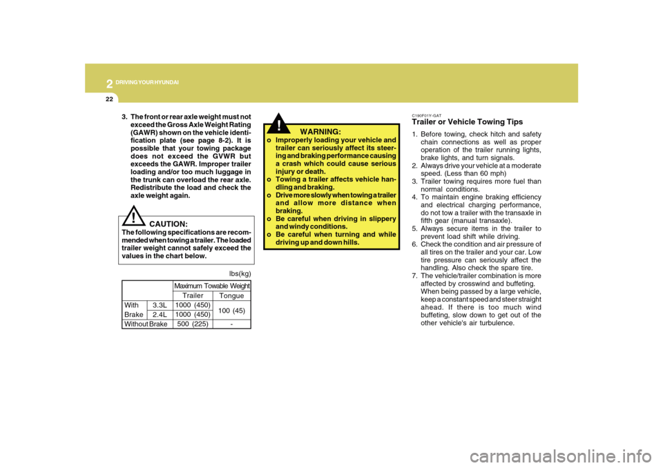
CAUTION:
The following specifications are recom-
mended when towing a trailer. The loaded
trailer weight cannot safely exceed the
values in the chart below.
WARNING:
o Improperly loading your vehicle and
trailer can seriously affect its steer-
ing and braking performance causing
a crash which could cause serious
injury or death.
o Towing a trailer affects vehicle han-
dling and braking.
o Drive more slowly when towing a trailer
and allow more distance when
braking.
o Be careful when driving in slippery
and windy conditions.
o Be careful when turning and while
driving up and down hills. 3. The front or rear axle weight must not
exceed the Gross Axle Weight Rating
(GAWR) shown on the vehicle identi-
fication plate (see page 8-2). It is
possible that your towing package
does not exceed the GVWR but
exceeds the GAWR. Improper trailer
loading and/or too much luggage in
the trunk can overload the rear axle.
Redistribute the load and check the
axle weight again.
Page 184 of 285
3
WHAT TO DO IN AN EMERGENCY
3
JUMP STARTING!
o If you should accidentally get acid on
your skin or in your eyes, immediately
remove any contaminated clothing and
flush the area with clean water for at
least 15 minutes. Then promptly obtain
medical attention. If you must be trans-
ported to an emergency facility, continue
to apply water to the affected area with
a sponge or cloth.
o The gas produced by the battery during
the jump-start operation is highly
explosive. Do not smoke or allow a
spark or an open flame in the vicinity.
o The battery being used to provide the
jump start must be 12-volt. If you cannot
determine that it is a 12-volt battery, do
not attempt to use it for the jump start.
o To jump start a car with a discharged
battery, follow this procedure exactly:
1. If the booster battery is installed in
another vehicle, be sure the two vehicles
are not touching.
2. Turn off all unnecessary lights and
acces-sories in both vehicles.
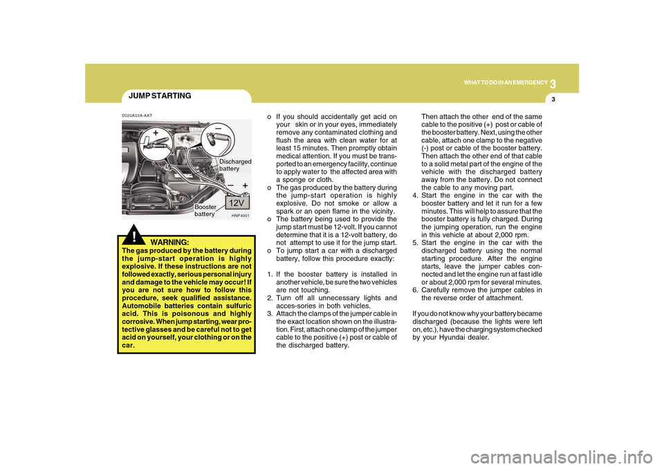
3. Attach the clamps of the jumper cable in
the exact location shown on the illustra-
tion. First, attach one clamp of the jumper
cable to the positive (+) post or cable of
the discharged battery.Then attach the other end of the same
cable to the positive (+) post or cable of
the booster battery. Next, using the other
cable, attach one clamp to the negative
(-) post or cable of the booster battery.
Then attach the other end of that cable
to a solid metal part of the engine of the
vehicle with the discharged battery
away from the battery. Do not connect
the cable to any moving part.
4. Start the engine in the car with the
booster battery and let it run for a few
minutes. This will help to assure that the
booster battery is fully charged. During
the jumping operation, run the engine
in this vehicle at about 2,000 rpm.
5. Start the engine in the car with the
discharged battery using the normal
starting procedure. After the engine
starts, leave the jumper cables con-
nected and let the engine run at fast idle
or about 2,000 rpm for several minutes.
6. Carefully remove the jumper cables in
the reverse order of attachment.
If you do not know why your battery became
discharged (because the lights were left
on, etc.), have the charging system checked
by your Hyundai dealer.
D020A03A-AAT
WARNING:
The gas produced by the battery during
the jump-start operation is highly
explosive. If these instructions are not
followed exactly, serious personal injury
and damage to the vehicle may occur! If
you are not sure how to follow this
procedure, seek qualified assistance.
Automobile batteries contain sulfuric
acid. This is poisonous and highly
corrosive. When jump starting, wear pro-
tective glasses and be careful not to get
acid on yourself, your clothing or on the
car.
HNF4001
Booster
batteryDischarged
battery
Page 241 of 285
6
DO-IT-YOURSELF MAINTENANCE
27
FOR MORE INFORMATION
ABOUT YOUR HYUNDAIG250A01A-AATIf you desire additional information about
maintaining and servicing your Hyundai,
you may purchase a factory Shop Manual
at your Hyundai dealer's parts department.
This is the same manual used by
dealership technicians and while it is highly
technical it can be useful in obtaining a
better understanding of your car and how
it works.
HEADLIGHT AIMING ADJUST-
MENTG290A03O-AATBefore performing aiming adjustment,
make sure of the following.
1. Keep all tires inflated to the correct
pressure.
2. Place the vehicle on level ground and
press the front bumper & rear bumper
down several times.
Place vehicle at a distance of 118 in.
(3m) from the test wall.
3. See that the vehicle is unloaded (except
for full levels of coolant, engine oil and
fuel, and spare tire, jack, and tools).
Have the driver or equivalent weight
placed in driver's seat.
4. Clean the headlight lenses and turn on
the headlights (Low beam).
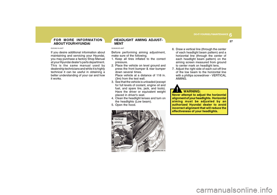
5. Open the hood.
G290A01NF-A
Vertical
aiming
!
6. Draw a vertical line (through the center
of each headlight beam pattern) and a
horizontal line (through the center of
each headlight beam pattern) on the
aiming screen measured from ground
to center mark on headlight lens.
7. Adjust the right side of each cut-off line
of the low beam to the horizontal line
with a phillips screwdriver - VERTICAL
AIMING.
WARNING:
Never attempt to adjust the horizontal
alignment of your headlights. Horizontal
aiming must be adjusted by an
authorized Hyundai dealer to avoid
incorrect alignment that will reduce the
effectiveness of your headlights.
Page 283 of 285

10
INDEX
4
Fuel
Capacity............................................................................ 9-2
Gauge..............................................................................1-58
Recommendations............................................................ 1-2
Fuel Filler Lid
Remote release ..............................................................1-87
Fuse Panel Description .....................................................6-37
Fuses..................................................................................6-22
G
General Checks ................................................................... 6-4
Glove Box ...........................................................................1-76
H
Hazard Warning System ....................................................1-68
Headlight
Aiming adjustment ..........................................................6-27
Replacement...................................................................6-28
Switch..............................................................................1-64
Heating and Ventilation
Air flow control ................................................... 1-97, 1-108
Air intake control switch ..................................... 1-99, 1-107
Bi-level heating .............................................................1-100
Defrosting/Defogging....................................................1-103
Fan speed control (Blower Control) .................. 1-97, 1-107
Temperature control .......................................................1-96
High-Mounted Rear Stop Light .........................................1-87
Hood Release ....................................................................1-89
Horn....................................................................................1-91I
Ignition Switch ...................................................................... 2-3
Instrument Cluster and Indicator Lights ............................1-50
Instrument Panel Light Control (Rheostat) .......................1-69
Interior Light .......................................................................1-74
Intermittent Wiper ...............................................................1-67
J
Jump Starting ....................................................................... 3-3
K
Key ........................................................................................ 1-3
If you lose your keys ......................................................3-17
Positions............................................................................ 2-3
L
Light Bulb Watages ............................................................6-36
Light Bulbs Replacement ..................................................6-28
Lubrication Chart .................................................................. 9-4
M
Maintenance Intervals
Explanation of scheduled maintenance items ................ 5-7
Maintenance under severe usage conditions ................. 5-6
Scheduled maintenance.................................................. 5-4
Service requirements ........................................................ 5-2
Manual Heating and Cooling Control System ..................1-96