Page 97 of 159
Navigation System97
System Setup
4. Rotate the Interface Dial knob so
the vehicle position arrowhead is
pointing in the corr ect direction, and
push in on the Interface Dial. The
display will return to the previous
screen.
NOTE:
If you continually have to do this, there
are either problems in the database or
GPS reception problems. See
Accessories Precautions on page 5.
5. As you drive, the current road will be displayed at the bottom of the screen.Color
From the SETUP screen (Other ), say
or select Color and the following
screen appears:
Map Color
Allows you to choose the map color
from one of four colors for the Day and
Night modes.
Say “Return” or press the CANCEL
button to return to the previous screen.
NOTE:
Choose “White” (factory default is Beige) as the Day color to obtain the
best daytime display contrast.
Choose “Black” (factory default) as the Night color to obtain the best
nighttime display contrast.
2010 Pilot
Page 98 of 159

98Navigation System
System Setup
Menu Color
Allows you to choose the menu color
from one of five colors for the Day and
Night modes.
Say “Return” or press the CANCEL
button to return to the previous screen.
NOTE:
Choose “Silver metal” (factory default) as the Day color to obtain
the best daytime display contrast.
Choose “Black metal” (factory default) as the Night color to obtain
the best nighttime display contrast.
Switching Display Mode
Manually
Pressing the Display Mode button
allows you to toggle through the
screen display modes: Day, Night , or
Off . This button is the overriding
control for the day/night display mode
and is the simplest way to control the
display mode.
NOTE:
Once this button is used, automatic day/
night switching is disabled until the next
key cycle. See item #1 on page 99.
See the chart on page 99 for an
explanation of other day/night display
mode adjustments and how they interact
with each other.
(Example of Day/Night Mode)
Day Mode Night Mode
2010 Pilot
Page 99 of 159

Navigation System99
System Setup
Switching Display Mode AutomaticallyI
Recommended Display Mode Day/Night Settings:
• With the headlights on, select mid-ra nge for the dash illumination (see your Owner’s Manual for location of knob).
• With the headlights off, select mid-range for the dash illumination (see your Owner’s Manual for location of knob).
• On the SETUP Color adjustment screen, choose white for the map Day display and black for the map Night display (see
page 98). Inappropriate adjustment of these colors can cause the Day/Night modes to appear inoperative.
llumination control Prior ity Operation But remember
Display Mode button
(see page 11) 1 Allows selection of
Day, Night, or Off display
mode. This button has the highest priority and
overrides all other displa y control adjustments
listed below. Once you press this button, you assume full
manual control of the display mode until the
ignition key is cycled again.
Sunlight sensor (see your
Owner’s Manual for location) 2 If the sunlight sensor
detects night-sky light
and the headlights are turned on, the system
automatically overrides (cancels) the Day
display and displays the Night display mode. If desired, use the
Display Mode
button
to override this automatic choice.
Dash illumination adjustment
knob (see your Owner’s
Manual for location) 3 When headlights are turned on, and you wish to
have the Day display mode, then adjust the
illumination to the full bright setting (beeps). With the headlights on, adjust the dash
brightness back to mid-range to allow auto
switching by sensing the headlights are on or
off.
Headlights (Auto/On/Off) 4 When turn ed on, the display changes to Night
display mode. The previous three controls
listed above can “cancel” this function. Use the
Display Mode
button , or with
the headlights on, adjust the dash illumination
to full bright to set the display to your desired
choice.
Map Day/Night screen color
choice (see page 98 for the
Day and Night color choices) N/A The user can select the color of the screen that
will be displayed for the Day and Night
display modes described above. For best contrast
, ensure that the map color is
white for Day and black for Night.
2010 Pilot
Page 100 of 159
100Navigation System
System Setup
• To allow the sunlight sensor to function properly, avoid blocking the sensor with loose articles (see your Owner’s Manual for location of sensor).
• Remember that once the Display Mode button is selected, the other display mode controls are overridden until the
vehicle is restarted.
NOTE:
Loose articles in the center dash can block or interfere with the operation of the sunlight sensor. See your Owner’s Manual for
additional information regarding the dash brightness adjustment.
2010 Pilot
Page 101 of 159
, say
or select System Information and the
following screen appears:
Displays the information on the
navigation")
Navigation System101
System Setup
System Information
From the SETUP screen ( Other), say
or select System Information and the
following screen appears:
Displays the information on the
navigation system software. This
information is for de aler use only. For
ordering updates, use the version
number stamped on the label (as Ver.
X.XX) of the navigation DVD. See
Obtaining a Navigation Update DVD on
page 109.
When finished, say or select Return to
return to the previous screen.
Rearview Camera
Your vehicle is equipped with a
rearview camera as shown in the
illustration.
Whenever you shift to R (Reverse) with
the ignition switch in the ON (II)
position, the rear view is shown on the
navigation screen. For the best image,
always keep the rearview camera lens
clean, and be sure it is not covered.
Since the rearview camera display area
is limited, you should always back up
slowly and carefully, and look behind
you for obstacles. NOTE:
The rearview camera has a special
lens that makes distances appear
closer than they actually are.
The rearview camera display has a limited range, and the size and
position of objects around the area
may appear different from reality.
Make sure to check the surrounding
area carefully.
Rearview Camera Brightness
Adjustment
When in reverse, the navigation “hard”
buttons are locked out, except the
rotating portion of the Interface Dial
(knob). Rotate the knob clockwise to
make the camera im age brighter, and
counterclockwise to darken the image.
This brightness adjustment is
independent of the screen brightness
adjustment in SETUP.
NOTE:
The camera brightness cannot be adjusted by voice control.
Slight delays can occur when switching to the ca mera image, or
switching back to the map/menu
screen. This is normal.
Rearview
Camera
2010 Pilot
Page 102 of 159
, the navigation system
will require i")
102Navigation System
System Initialization
System Initialization
If for any reason you lose power to the
navigation system (e.g., the battery was
disconnected), the navigation system
will require initialization. Once
completed, your system will be ready to
use.
This initialization requires the
following:
• Entry of the 4-digit anti-theft security code.
• GPS initialization (may not be needed depending on the length of time the
system was without power).
• Map matching to align the GPS coordinates to a place on the map
(displays current street at the bottom
of the map).
Entering the Security Code
If the battery goes dead or is
disconnected for any reason, you will
have to enter a secur ity code for both the
audio system and the navigation system
before you can use it again.
When you purchased the vehicle, you
should have received two cards
containing the audio and navigation
system’s security codes and serial
numbers. Keep these cards in a safe
place in case you need the codes. If you
lose the cards, you must obtain the
security codes from your dealer. Enter the four-digit s
ecurity code. If you
have entered it corr ectly, the display
changes to the Disclaimer screen. If
you make a mistake, the system will
display “INCORRECT PIN.” Re-enter
your 4-digit security code. You have ten
chances to enter the correct code. If all
ten are incorrect, tu rn the ignition to
OFF, then back to ON (II) to have ten
more chances to enter the correct code.
Follow the instructions in your Owner’s
Manual to enter the 5-digit audio code.
The navigation voice will not operate if
the audio code is not entered.
NOTE:
The anti-theft security code is unrelated
to your optional navigation system PIN
(for Personal or Home Address).
2010 Pilot
Page 103 of 159

Navigation System103
System Initialization
GPS Initialization
Depending on the length of time the
battery was disconnected, your system
may require GPS initialization. If it
does, the following screen appears:
If this procedure is not necessary, the
system proceeds directly to the
Disclaimer screen (see page 17).
During initialization, the system
searches for all available GPS satellites
and obtains their orbital information.
During this procedure, the vehicle
should be out in th e open with a clear
view of the sky. If the navigation system finds the
satellites properly, this box clears and
the
Disclaimer screen is shown. If
within 10 minutes the system fails to
locate a sufficient number of satellites to
locate your position, the following
screen appears:
If the system is still unable to acquire a
signal, follow the instructions on the
screen, or contact you r local dealer for
assistance.
NOTE:
The average acquiring time is less than
10 minutes, but it can take as long as 45
minutes.
Map Matching
This part of the initialization matches
the GPS coordinates found above with a
road on the map screen. To perform this
part of the procedure, ensure that the
navigation system is displaying a map,
and drive the vehicle on a mapped road
(a road shown on the map screen). Do
not enter a destina tion at this time.
When the name of the current road you
are driving on appears at the bottom of
the screen, the entire procedure is
complete. Your system is now ready to
use.
The navigation system lost power and is acquiring its
location from the GPS satellites. This usually takes
less than 10 minutes.
* Start the engine.
* Park the vehicle in an open area away from trees,
power lines, and tall buildings.
* Remove loose articles, cell phones, or electrical
accessories located near the GPS antenna.
* If this screen is displayed repeatedly when starting
the vehicle, see your dealer.
Something is interfering with the system’s ability to
acquire its location. Check the following:
* The vehicle must be in an open area with a clear
view of the sky.
* Remove sources of GPS interference like metallic
window tint above antenna, or electrical items
near antenna (see owner's manual for details).
* Check GPS antenna cable connection.
* Restart the engine and repeat the GPS acquire
procedure. If the problem persists, see your dealer.
2010 Pilot
Page 104 of 159

104Navigation System
System Limitations
Although your navigation system is one
of the most highly sophisticated pieces
of equipment you will find in a modern
automobile, you may find during its use
that it has certain limitations.
The system uses GPS signals to aid in
determining its current location. The
GPS is operated by the U.S.
Department of Defense. For security
reasons, there are certain inaccuracies
built into the GPS that the navigation
system must constantly compensate for.
This can cause occasional positioning
errors of up to several hundred feet.
For example, in urban areas where
streets are close together, this could
cause the system to show that you are
traveling on a street that parallels the
street you are actually on. The system
will, under most circumstances, correct
itself while you drive. Depending on your current view of the
sky and the position of the satellites, the
elevation may be shown incorrectly.
You may also notice some delay of the
vehicle position icon at intersections;
this is normal.
GPS Reception IssuesThe signals received from the GPS
satellites are extremely weak (less than
a millionth of the strength of a local FM
station) and requir
e an unobstructed
view of sky. The signal can easily be
interrupted or interfered with by the
following:
• Aftermarket metallic window tint above or to the sides of the GPS
antenna (located under the
dashboard)
• Cell phones, PDAs, or other electronic devices docked in a cradle
or lying loose on the dashboard
• Radar detectors mounted on the dashboard
• Remote starters, or “hidden” vehicle tracking systems mounted near the
navigation unit • Other aftermarket audio electronic
devices mounted near the navigation
unit
• Trees, tall buildings, freeway overpasses, tunnels, or overhead
electrical power wires
Although the system will direct you to
your desired destination, it may not
always generate what you consider to be
the most direct rout e. Try changing the
method of routing. See Changing
Routing Method on page47. You may
also have Unverified Area Routing set
to OFF. See Unverified Area Routing on
page 86.
Additionally, the mapping database
contains verified and unverified maps.
See Map Overview on page6.
A Disclaimer screen will warn you if
your route includes unverified streets.
Unverified streets may be missing from
the map, in the wrong location, or have
an incorrect name or address range.
Exercise addition al caution when
driving in these unverified areas.
2010 Pilot
 1
1 2
2 3
3 4
4 5
5 6
6 7
7 8
8 9
9 10
10 11
11 12
12 13
13 14
14 15
15 16
16 17
17 18
18 19
19 20
20 21
21 22
22 23
23 24
24 25
25 26
26 27
27 28
28 29
29 30
30 31
31 32
32 33
33 34
34 35
35 36
36 37
37 38
38 39
39 40
40 41
41 42
42 43
43 44
44 45
45 46
46 47
47 48
48 49
49 50
50 51
51 52
52 53
53 54
54 55
55 56
56 57
57 58
58 59
59 60
60 61
61 62
62 63
63 64
64 65
65 66
66 67
67 68
68 69
69 70
70 71
71 72
72 73
73 74
74 75
75 76
76 77
77 78
78 79
79 80
80 81
81 82
82 83
83 84
84 85
85 86
86 87
87 88
88 89
89 90
90 91
91 92
92 93
93 94
94 95
95 96
96 97
97 98
98 99
99 100
100 101
101 102
102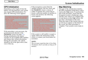 103
103 104
104 105
105 106
106 107
107 108
108 109
109 110
110 111
111 112
112 113
113 114
114 115
115 116
116 117
117 118
118 119
119 120
120 121
121 122
122 123
123 124
124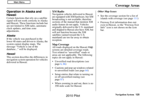 125
125 126
126 127
127 128
128 129
129 130
130 131
131 132
132 133
133 134
134 135
135 136
136 137
137 138
138 139
139 140
140 141
141 142
142 143
143 144
144 145
145 146
146 147
147 148
148 149
149 150
150 151
151 152
152 153
153 154
154 155
155 156
156 157
157 158
158
.
• Remember")