2010 GMC YUKON XL towing
[x] Cancel search: towingPage 407 of 614

Four-Wheel Drive Vehicles with a Two
Speed Automatic Transfer Case
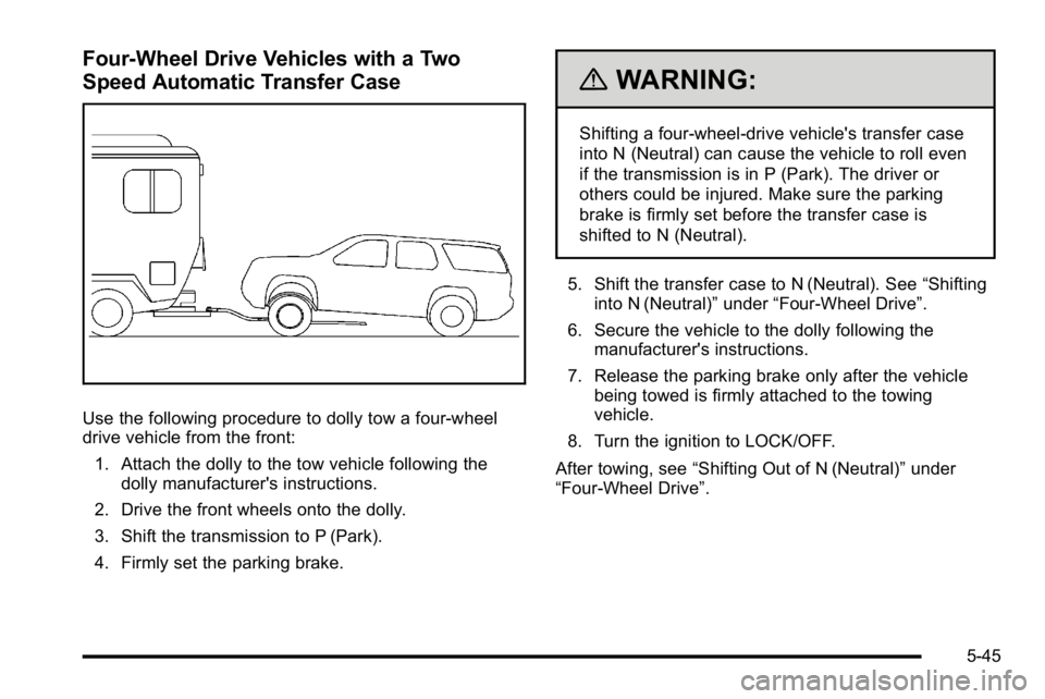
Use the following procedure to dolly tow a four-wheel
drive vehicle from the front:1. Attach the dolly to the tow vehicle following the dolly manufacturer's instructions.
2. Drive the front wheels onto the dolly.
3. Shift the transmission to P (Park).
4. Firmly set the parking brake.
{WARNING:
Shifting a four-wheel-drive vehicle's transfer case
into N (Neutral) can cause the vehicle to roll even
if the transmission is in P (Park). The driver or
others could be injured. Make sure the parking
brake is firmly set before the transfer case is
shifted to N (Neutral).
5. Shift the transfer case to N (Neutral). See “Shifting
into N (Neutral)” under“Four-Wheel Drive”.
6. Secure the vehicle to the dolly following the manufacturer's instructions.
7. Release the parking brake only after the vehicle being towed is firmly attached to the towing
vehicle.
8. Turn the ignition to LOCK/OFF.
After towing, see “Shifting Out of N (Neutral)” under
“Four-Wheel Drive”.
5-45
Page 408 of 614

Rear Towing (Rear Wheels Off the
Ground)Two-Wheel-Drive Vehicles and Four-Wheel
Drive Vehicles with a Single Speed
Automatic Transfer Case
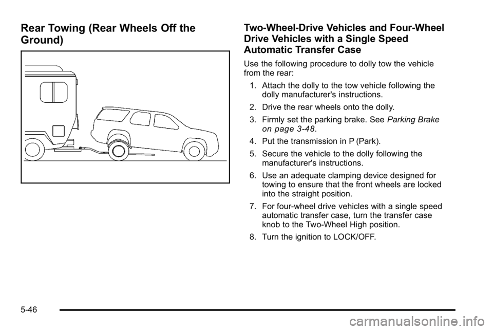
Use the following procedure to dolly tow the vehicle
from the rear:1. Attach the dolly to the tow vehicle following the dolly manufacturer's instructions.
2. Drive the rear wheels onto the dolly.
3. Firmly set the parking brake. See Parking Brake
on page 3‑48.
4. Put the transmission in P (Park).
5. Secure the vehicle to the dolly following the manufacturer's instructions.
6. Use an adequate clamping device designed for towing to ensure that the front wheels are locked
into the straight position.
7. For four-wheel drive vehicles with a single speed automatic transfer case, turn the transfer case
knob to the Two-Wheel High position.
8. Turn the ignition to LOCK/OFF.
5-46
Page 409 of 614

Four-Wheel Drive Vehicles with a
Two Speed Automatic Transfer Case
Use the following procedure to dolly tow a four-wheel
drive vehicle from the rear:1. Attach the dolly to the tow vehicle following the dolly manufacturer's instructions.
2. Drive the rear wheels onto the dolly.
3. Firmly set the parking brake. See Parking Brake
on page 3‑48.
4. Put the transmission in P (Park).
5. Secure the vehicle to the dolly following the manufacturer's instructions.
6. Use an adequate clamping device designed for towing to ensure that the front wheels are locked
into the straight position.
{WARNING:
Shifting a four-wheel-drive vehicle's transfer case
into N (Neutral) can cause the vehicle to roll even
if the transmission is in P (Park). The driver or
others could be injured. Make sure the parking
brake is firmly set before the transfer case is
shifted to N (Neutral).
7. Shift the transfer case to N (Neutral). See “Shifting
into N (Neutral)” under“Four-Wheel Drive”.
8. Turn the ignition to LOCK/OFF.
After towing, see “Shifting Out of N (Neutral)” under
“Four-Wheel Drive”.
5-47
Page 410 of 614

Level Control
Automatic Level Control
The automatic level control rear suspension is available
on light‐duty vehicles and comes as a part of the
Autoride
®suspension, if equipped.
This type of level control is fully automatic and will
provide a better leveled riding position as well as
better handling under a variety of passenger and
loading conditions. An air compressor connected to
the rear shocks will raise or lower the rear of the
vehicle to maintain proper vehicle height. The system
is activated when the ignition key is turned to ON/RUN
and will automatically adjust vehicle height thereafter.
The system may exhaust (lower vehicle height) for up
to ten minutes after the ignition key has been turned off.
You may hear the air compressor operating when the
height is being adjusted.
If a weight‐distributing hitch is being used, it is
recommended to allow the shocks to inflate, thereby
leveling the vehicle prior to adjusting the hitch.
Autoride®
With this feature, improved vehicle ride and handling is
provided under a variety of passenger and loading
conditions.
The system is fully automatic and uses a computer
controller to continuously monitor vehicle speed, wheel
to body position, lift/dive and steering position of the
vehicle. The controller then sends signals to each shock
absorber to independently adjust the damping level to
provide the optimum vehicle ride.
Autoride also interacts with the tow/haul mode that,
when activated, will provide additional control of the
shock absorbers. This additional control results in better
ride and handling characteristics when the vehicle is
loaded or towing a trailer. See “Tow/Haul Mode”under
Towing a Trailer
on page 5‑49for more information.
5-48
Page 411 of 614

Towing a Trailer
If the vehicle has a two–mode hybrid engine, see the
Two–mode Hybrid manual for more information.
Do not tow a trailer during break‐in. SeeNew Vehicle
Break-In
on page 3‑27for more information.
{WARNING:
The driver can lose control when pulling a trailer if
the correct equipment is not used or the vehicle is
not driven properly. For example, if the trailer is
too heavy, the brakes may not work well —or
even at all. The driver and passengers could
be seriously injured. The vehicle may also be
damaged; the resulting repairs would not be
covered by the vehicle warranty. Pull a trailer only
if all the steps in this section have been followed.
Ask your dealer for advice and information about
towing a trailer with the vehicle. Notice:
Pulling a trailer improperly can damage
the vehicle and result in costly repairs not covered
by the vehicle warranty. To pull a trailer correctly,
follow the advice in this section and see your dealer
for important information about towing a trailer with
the vehicle.
To identify the trailering capacity of the vehicle, read the
information in “Weight of the Trailer” that appears later
in this section.
Trailering is different than just driving the vehicle
by itself. Trailering means changes in handling,
acceleration, braking, durability and fuel economy.
Successful, safe trailering takes correct equipment,
and it has to be used properly.
The following information has many time-tested,
important trailering tips and safety rules. Many of
these are important for your safety and that of your
passengers. So please read this section carefully
before pulling a trailer.
5-49
Page 420 of 614

The ITBC system is powered through the vehicle's
electrical system. Turning the ignition off will also turn
off the ITBC system. The ITBC system is fully functional
only when the ignition is in ON or in RUN.
The ITBC system can only be used with trailers with
electric brakes.
{WARNING:
Connecting a trailer that is not compatible with the
ITBC system may result in reduced or complete
loss of trailer braking. There may be an increase
in stopping distance or trailer instability which
could result in personal injury or damage to the
vehicle, trailer, or other property. An aftermarket
controller may be available for use with trailers
with surge, air or electric‐over‐hydraulic trailer
brake systems. To determine the type of brakes
on the trailer and the availability of controllers,
check with your trailer manufacturer or dealer.When trailering, make sure of the following:
.The ITBC system is used only with trailers that are
equipped with electric brakes.
.All applicable local and federal laws and
regulations are followed.
.All electrical and mechanical connections to the
trailer are made correctly.
.The trailer
’s brakes are in proper working
condition.
.The trailer and vehicle are properly loaded for the
towing condition.
The ITBC system is a factory installed item.
Out‐of‐factory installation of this system should
not be attempted. GM is not responsible for warranty or
performance of the system resulting from out‐of‐factory
installation.
5-58
Page 423 of 614

Manual Trailer Brake Apply
The Manual Trailer Brake Apply Lever is located on the
Trailer Brake Control Panel and is used to apply the
trailer’s electric brakes independent of the vehicle’ s
brakes. This lever is used in the Trailer Gain Adjustment
Procedure to properly adjust the power output to the
trailer brakes. Sliding the lever to the left will apply only
the trailer brakes. The power output to the trailer is
indicated in the Trailer Brake Display Page in the DIC.
If the vehicle’s service brakes are applied while using
the Manual Trailer Brake Apply Lever, the trailer output
power will be the greater of the two.
The trailer and the vehicle's brake lamps will come on
when either vehicle braking or manual trailer brakes are
applied.
Trailer Gain Adjustment Procedure
Trailer Gain should be set for a specific trailering
condition and must be adjusted any time vehicle
loading, trailer loading or road surface conditions
change.
Setting the Trailer Gain properly is needed for the
best trailer stopping performance. A trailer that is
over-gained may result in locked trailer brakes. A trailer
that is under-gained may result in not enough trailer
braking. Both of these conditions may result in poorer
stopping and stability of the vehicle and trailer. Use the following procedure to correctly adjust Trailer
Gain for each towing condition:
1. Make sure the trailer brakes are in proper working condition.
2. Connect a properly loaded trailer to the vehicle and make all necessary mechanical and electrical
connections. See Loading the Vehicle
on
page 5‑31for more information.
3. After the electrical connection is made to a trailer equipped with electric brakes:
.A TRAILER CONNECTED message will be
briefly displayed on the DIC display.
.The Trailer Brake Display Page will appear
on the DIC showing TRAILER GAIN and
TRAILER OUTPUT.
.In the Trailer Output display on the DIC,
“- - - - - -“ will disappear if there is no error
present. Connecting a trailer without electric
brakes will not clear the six dashed lines.
4. Adjust the Trailer Gain by using the gain adjustment (+ / -) buttons on the Trailer Brake
Control Panel.
5-61
Page 424 of 614

5. Drive the vehicle with the trailer attached on alevel road surface representative of the towing
condition and free of traffic at about 20 to 25 mph
(32 to 40 km/h) and fully apply the Manual Trailer
Brake Apply lever.
Adjusting trailer gain at speeds lower than
20 to 25 mph (32 to 40 km/h) may result in an
incorrect gain setting.
6. Adjust the Trailer Gain to just below the point of trailer wheel lock-up, indicated by trailer wheel
squeal or tire smoke when a trailer wheel locks.
Trailer wheel lock-up may not occur if towing a
heavily loaded trailer. In this case, adjust the
Trailer Gain to the highest allowable setting for
the towing condition.
7. Re-adjust Trailer Gain any time vehicle loading, trailer loading or road surface conditions change or
if trailer wheel lock-up is noticed at any time while
towingOther ITBC Related DIC Messages
In addition to displaying TRAILER GAIN and TRAILER
OUTPUT through the DIC, trailer connection and ITBC
system status is displayed in the DIC.
TRAILER CONNECTED –This message will be
briefly displayed when a trailer with electric brakes
is first connected to the vehicle. This message will
automatically turn off in about ten seconds. The driver
can also acknowledge this message before it
automatically turns off.
CHECK TRAILER WIRING –This message will be
displayed if:
1. The ITBC system first determines connection to a trailer with electric brakes and then the trailer
harness becomes disconnected from the vehicle.
If the disconnect occurs while the vehicle is
stationary, this message will automatically turn off
in about thirty seconds. This message will also turn
off if the driver acknowledges this message off or if
the trailer harness is re-connected.
If the disconnect occurs while the vehicle is
moving, this message will continue until the ignition
is turned off. This message will also turn off if the
driver acknowledges this message off or if the
trailer harness is re-connected.
5-62