2010 GMC YUKON HYBRID parking brake
[x] Cancel search: parking brakePage 52 of 120
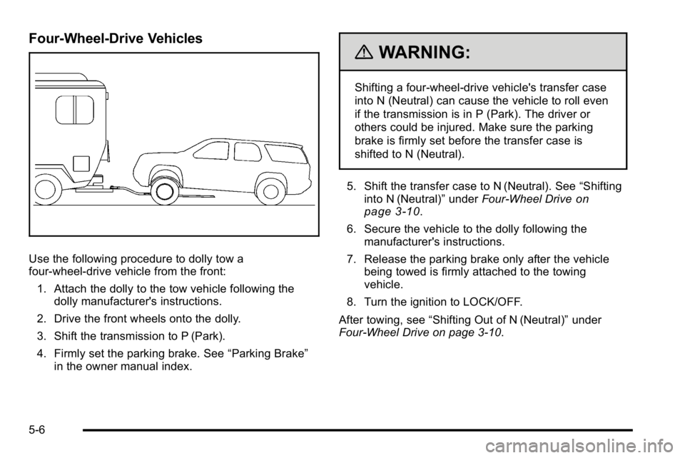
Four-Wheel-Drive Vehicles
Use the following procedure to dolly tow a
four-wheel-drive vehicle from the front:1. Attach the dolly to the tow vehicle following the dolly manufacturer's instructions.
2. Drive the front wheels onto the dolly.
3. Shift the transmission to P (Park).
4. Firmly set the parking brake. See “Parking Brake”
in the owner manual index.
{WARNING:
Shifting a four-wheel-drive vehicle's transfer case
into N (Neutral) can cause the vehicle to roll even
if the transmission is in P (Park). The driver or
others could be injured. Make sure the parking
brake is firmly set before the transfer case is
shifted to N (Neutral).
5. Shift the transfer case to N (Neutral). See “Shifting
into N (Neutral)” underFour-Wheel Drive
on
page 3‑10.
6. Secure the vehicle to the dolly following the manufacturer's instructions.
7. Release the parking brake only after the vehicle being towed is firmly attached to the towing
vehicle.
8. Turn the ignition to LOCK/OFF.
After towing, see “Shifting Out of N (Neutral)” under
Four-Wheel Drive on page 3‑10.
5-6
Page 53 of 120
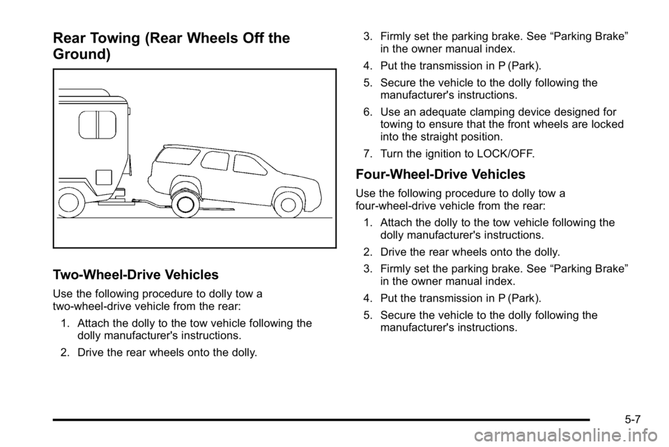
Rear Towing (Rear Wheels Off the
Ground)
Two‐Wheel‐Drive Vehicles
Use the following procedure to dolly tow a
two-wheel-drive vehicle from the rear:
1. Attach the dolly to the tow vehicle following the dolly manufacturer's instructions.
2. Drive the rear wheels onto the dolly. 3. Firmly set the parking brake. See
“Parking Brake”
in the owner manual index.
4. Put the transmission in P (Park).
5. Secure the vehicle to the dolly following the manufacturer's instructions.
6. Use an adequate clamping device designed for towing to ensure that the front wheels are locked
into the straight position.
7. Turn the ignition to LOCK/OFF.
Four‐Wheel‐Drive Vehicles
Use the following procedure to dolly tow a
four-wheel-drive vehicle from the rear: 1. Attach the dolly to the tow vehicle following the dolly manufacturer's instructions.
2. Drive the rear wheels onto the dolly.
3. Firmly set the parking brake. See “Parking Brake”
in the owner manual index.
4. Put the transmission in P (Park).
5. Secure the vehicle to the dolly following the manufacturer's instructions.
5-7
Page 54 of 120

6. Use an adequate clamping device designed fortowing to ensure that the front wheels are locked
into the straight position.
{WARNING:
Shifting a four-wheel-drive vehicle's transfer case
into N (Neutral) can cause the vehicle to roll even
if the transmission is in P (Park). The driver or
others could be injured. Make sure the parking
brake is firmly set before the transfer case is
shifted to N (Neutral).
7. Shift the transfer case to N (Neutral). See “Shifting
into N (Neutral)” underFour-Wheel Drive
on
page 3‑10
8. Turn the ignition to LOCK/OFF.
After towing, see “Shifting Out of N (Neutral)” under
Four-Wheel Drive on page 3‑10.
Towing a Trailer
For more information, see “Towing a Trailer”in the
owner manual Index.
Weight of the Trailer
How heavy can a trailer safely be?
It depends on how the rig is used. For example, speed,
altitude, road grades, outside temperature and how
much the vehicle is used to pull a trailer are all
important. It can depend on any special equipment
on the vehicle, and the amount of tongue weight the
vehicle can carry.
Maximum trailer weight is calculated assuming only the
driver is in the tow vehicle and it has all the required
trailering equipment. The weight of additional optional
equipment, passengers and cargo in the tow vehicle
must be subtracted from the maximum trailer weight.
Use the following charts to determine how much the
vehicle can weigh, based upon the vehicle model and
options.
5-8
Page 62 of 120

How to Check Automatic Transmission
Fluid
Notice:Too much or too little fluid can damage your
transmission. Too much can mean that some of the
fluid could come out and fall on hot engine parts or
exhaust system parts, starting a fire. Too little fluid
could cause the transmission to overheat. Be sure
to get an accurate reading if you check your
transmission fluid.
Before checking the fluid level, prepare the vehicle as
follows:
1. Start the engine and park the vehicle on a level surface. Keep the engine running.
2. Apply the parking brake and place the shift lever in P (Park).
3. With your foot on the brake pedal, move the shift lever through each gear range, pausing for about
three seconds in each range. Then, move the shift
lever back to P (Park).
4. Allow the engine to idle (500 –800 RPM) for at
least one minute. Slowly release the brake pedal.
5. Keep the engine running and press the Trip/Fuel button or trip odometer reset stem until TRANS
TEMP (Transmission Temperature) displays on the
Driver Information Center (DIC). 6. Using the TRANS TEMP reading, determine and
perform the appropriate check procedure. If the
TRANS TEMP reading is not within the required
temperature ranges, allow the vehicle to cool,
or operate the vehicle until the appropriate
transmission fluid temperature is reached.
Cold Check Procedure
Use this procedure only as a reference to determine if
the transmission has enough fluid to be operated safely
until a hot check procedure can be made. The hot
check procedure is the most accurate method to check
the fluid level. Perform the hot check procedure at the
first opportunity. Use this cold check procedure to check
fluid level when the transmission temperature is
between 24°C and 34°C (75°F and 93°F).
1. Locate the
transmission dipstick at
the rear of the engine
compartment, on the
passenger side of the
vehicle.
See Engine Compartment Overview
on page 6‑4for more information.
2. Pull out the dipstick and wipe it with a clean rag or paper towel.
6-6
Page 75 of 120

2. Get the vehicles close enough so the jumpercables can reach, but be sure the vehicles are not
touching each other. It could cause a ground
connection you do not want. You would not be able
to start your vehicle, and the bad grounding could
damage the electrical systems.
To avoid the possibility of the vehicles rolling, set
the parking brake firmly on both vehicles involved
in the jump start procedure. Put the automatic
transmission in P (Park) or a manual transmission
in N (Neutral) before setting the parking brake.
If you have a four-wheel-drive vehicle, be sure the
transfer case is in a drive gear, not in N (Neutral).
Notice: If you leave the radio or other accessories
on during the jump starting procedure, they could
be damaged. The repairs would not be covered by
the warranty. Always turn off the radio and other
accessories when jump starting the vehicle. 3. Turn off the ignition on both vehicles. Unplug
unnecessary accessories plugged into the
cigarette lighter or the accessory power outlets.
Turn off the radio and all the lamps that are not
needed.
This avoids sparks and helps save both batteries.
It could save the radio!
4. Open the hood on the other vehicle and locate the positive (+) and negative (−) terminal locations on
that vehicle.
Your vehicle has a remote positive (+) and a
remote negative (−) jump starting terminal.
You should always use these remote terminals
instead of the terminals on the battery.
6-19
Page 88 of 120

TPMS Sensor Matching Process
Each TPMS sensor has a unique identification code.
Any time you rotate your vehicle's tires or replace one
or more of the TPMS sensors, the identification codes
will need to be matched to the new tire/wheel position.
The sensors are matched to the tire/wheel positions in
the following order: driver side front tire, passenger
side front tire, passenger side rear tire, and driver side
rear tire using a TPMS diagnostic tool. See your
dealer/retailer for service.
The TPMS sensors can also be matched to each
tire/wheel position by increasing or decreasing the
tire's air pressure. If increasing the tire's air pressure,
do not exceed the maximum inflation pressure indicated
on the tire's sidewall.
To decrease air-pressure out of a tire you can use the
pointed end of the valve cap, a pencil-style air pressure
gage, or a key.
You have two minutes to match the first tire/wheel
position, and five minutes overall to match all four
tire/wheel positions. If it takes longer than two minutes,
to match the first tire and wheel, or more than
five minutes to match all four tire and wheel positions
the matching process stops and you need to start over.The TPMS sensor matching process is outlined below:
1. Set the parking brake.
2. Turn the ignition switch to ON/RUN with the engine off.
3. Press
QandKon the Remote Keyless Entry
(RKE) transmitter at the same time for
approximately five seconds. The horn sounds
twice to signal the receiver is in relearn mode and
TIRE LEARNING ACTIVE message displays on
the DIC screen.
4. Start with the driver side front tire.
5. Remove the valve cap from the valve cap stem. Activate the TPMS sensor by increasing or
decreasing the tire's air pressure for five seconds,
or until a horn chirp sounds. The horn chirp, which
may take up to 30 seconds to sound, confirms that
the sensor identification code has been matched to
this tire and wheel position.
6. Proceed to the passenger side front tire, and repeat the procedure in Step 5.
7. Proceed to the passenger side rear tire, and repeat the procedure in Step 5.
6-32
Page 91 of 120
If a tire goes flat, avoid further tire and wheel damage
by driving slowly to a level place and stopping.
Then do this:1. Turn on the hazard warning flashers.
2. Park your vehicle. Set the parking brake firmly and put the shift lever in PARK (P).
3. Turn off the engine.
4. Inspect the flat tire.
If the tire has been separated from the wheel or has
damaged sidewalls or large tears that allow rapid air
loss, call a tire repair facility. See “Roadside Assistance
Program” in the Index of the owner manual.
If the flat tire is due to a slow leak caused by a nail or
other similar road hazard, the tire inflator kit may be
used to repair the damaged tire temporarily. The kit
uses a liquid tire sealant to seal small punctures in the
tread area of the tire.
After repairing a tire with the tire inflator kit, take your
vehicle to an authorized retailer to have the tire
inspected and repaired as soon as possible. The tire
sealant is a temporary repair only. See Tire Sealant
and Compressor Kit (Without Selector Switch)
on
page 6‑35or Tire Sealant and Compressor Kit
(With Selector Switch) on page 6‑45.
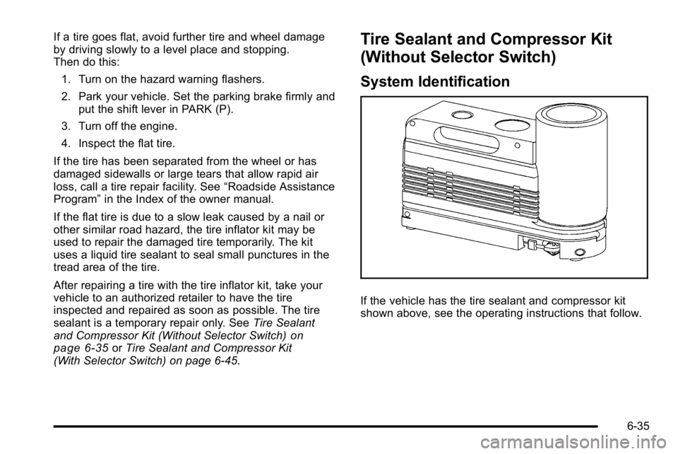
Tire Sealant and Compressor Kit
(Without Selector Switch)
System Identification
If the vehicle has the tire sealant and compressor kit
shown above, see the operating instructions that follow.
6-35