2010 GMC SIERRA Four wheel drive
[x] Cancel search: Four wheel drivePage 415 of 630

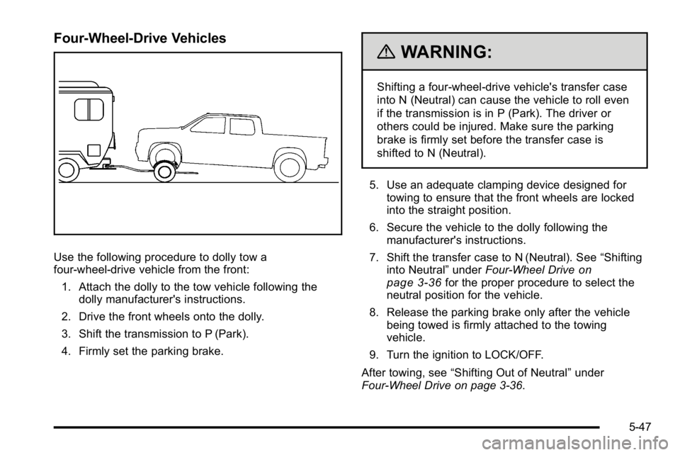
Four-Wheel-Drive Vehicles
Use the following procedure to dolly tow a
four-wheel-drive vehicle from the front:1. Attach the dolly to the tow vehicle following the dolly manufacturer's instructions.
2. Drive the front wheels onto the dolly.
3. Shift the transmission to P (Park).
4. Firmly set the parking brake.
{WARNING:
Shifting a four-wheel-drive vehicle's transfer case
into N (Neutral) can cause the vehicle to roll even
if the transmission is in P (Park). The driver or
others could be injured. Make sure the parking
brake is firmly set before the transfer case is
shifted to N (Neutral).
5. Use an adequate clamping device designed for towing to ensure that the front wheels are locked
into the straight position.
6. Secure the vehicle to the dolly following the manufacturer's instructions.
7. Shift the transfer case to N (Neutral). See “Shifting
into Neutral” underFour-Wheel Drive
on
page 3‑36for the proper procedure to select the
neutral position for the vehicle.
8. Release the parking brake only after the vehicle being towed is firmly attached to the towing
vehicle.
9. Turn the ignition to LOCK/OFF.
After towing, see “Shifting Out of Neutral” under
Four-Wheel Drive on page 3‑36.
5-47
Page 417 of 630

Four‐Wheel‐Drive Vehicles
Use the following procedure to dolly tow a
four-wheel-drive vehicle from the rear:1. Attach the dolly to the tow vehicle following the dolly manufacturer's instructions.
2. Drive the rear wheels onto the dolly.
3. Firmly set the parking brake. See Parking Brake
on page 3‑50.
4. Put the transmission in P (Park).
5. Secure the vehicle to the dolly following the manufacturer's instructions.
6. Use an adequate clamping device designed for towing to ensure that the front wheels are locked
into the straight position.
{WARNING:
Shifting a four-wheel-drive vehicle's transfer case
into N (Neutral) can cause the vehicle to roll even
if the transmission is in P (Park). The driver or
others could be injured. Make sure the parking
brake is firmly set before the transfer case is
shifted to N (Neutral).
7. Shift the transfer case to N (Neutral). See “Shifting
into Neutral” underFour-Wheel Drive
on
page 3‑36for the proper procedure to select the
neutral position for the vehicle.
8. Turn the ignition to LOCK/OFF.
After towing, see “Shifting Out of Neutral” under
Four-Wheel Drive on page 3‑36.
5-49
Page 441 of 630

2. Have someone place chocks under the trailerwheels.
3. When the wheel chocks are in place, release the regular brakes until the chocks absorb the load.
4. Reapply the brake pedal. Then apply the parking brake and shift into P (Park).
5. If the vehicle is four-wheel-drive, be sure the transfer case is in a drive gear and not in
N (Neutral).
6. Release the brake pedal.
{WARNING:
It can be dangerous to get out of the vehicle if the
shift lever is not fully in P (Park) with the parking
brake firmly set. The vehicle can roll.
If the engine has been left running, the vehicle
can move suddenly. You or others could be
injured. To be sure the vehicle will not move, even
when on fairly level ground, use the steps that
follow. (Continued)
WARNING: (Continued)
Always put the shift lever fully in P (Park) with the
parking brake firmly set.
If the transfer case on a four-wheel-drive vehicle
is in N (Neutral), the vehicle will be free to roll,
even if the shift lever is in P (Park). Be sure the
transfer case is in a drive gear—not in
N (Neutral).
Leaving After Parking on a Hill
1. Apply and hold the brake pedal.
2. Start the engine
3. Shift into a gear
4. Release the parking brake
5. Let up on the brake pedal.
6. Drive slowly until the trailer is clear of the chocks.
7. Stop and have someone pick up and store the chocks.
5-73
Page 448 of 630

Section 6 Service and Appearance Care
Rear Axle. . . . . . . . . . . . . . . . . . . . . . . . . . . . . . . . . . . . . . . . . 6-48
Four-Wheel Drive . . . . . . . . . . . . . . . . . . . . . . . . . . . . . . . . . 6-50
Front Axle . . . . . . . . . . . . . . . . . . . . . . . . . . . . . . . . . . . . . . . . . 6-52
Noise Control System . . . . . . . . . . . . . . . . . . . . . . . . . . . . 6-53
Tampering with Noise Control
System Prohibited . . . . . . . . . . . . . . . . . . . . . . . . . . 6-53
Headlamp Aiming . . . . . . . . . . . . . . . . . . . . . . . . . . . . . . . . 6-54
Bulb Replacement . . . . . . . . . . . . . . . . . . . . . . . . . . . . . . . . 6-57
Halogen Bulbs . . . . . . . . . . . . . . . . . . . . . . . . . . . . . . . . . 6-57
Headlamps . . . . . . . . . . . . . . . . . . . . . . . . . . . . . . . . . . . . 6-57
Center High-Mounted Stoplamp (CHMSL) and Cargo Lamp . . . . . . . . . . . . . . . . . . . . . . . . . . . . . 6-58
Pickup Box Identification and Fender Marker Lamps . . . . . . . . . . . . . . . . . . 6-59
Taillamps, Turn Signal, Stoplamps and Back-up Lamps . . . . . . . . . . . . . . . . . . . . . . . . 6-60
License Plate Lamp . . . . . . . . . . . . . . . . . . . . . . . . . . . . 6-62
Replacement Bulbs . . . . . . . . . . . . . . . . . . . . . . . . . . . . 6-62
Windshield Wiper Blade Replacement . . . . . . . . . . .6-63Tires
. . . . . . . . . . . . . . . . . . . . . . . . . . . . . . . . . . . . . . . . . . . . . . . 6-64
Tire Sidewall Labeling . . . . . . . . . . . . . . . . . . . . . . . . . 6-65
Tire Terminology and Definitions . . . . . . . . . . . . . . . 6-70
Inflation - Tire Pressure . . . . . . . . . . . . . . . . . . . . . . . . 6-72
High-Speed Operation . . . . . . . . . . . . . . . . . . . . . . . . . 6-74
Dual Tire Operation . . . . . . . . . . . . . . . . . . . . . . . . . . . . 6-74
Tire Pressure Monitor System . . . . . . . . . . . . . . . . . 6-75
Tire Pressure Monitor Operation . . . . . . . . . . . . . . . 6-76
Tire Inspection and Rotation . . . . . . . . . . . . . . . . . . . 6-80
When It Is Time for New Tires . . . . . . . . . . . . . . . . . 6-82
Buying New Tires . . . . . . . . . . . . . . . . . . . . . . . . . . . . . . 6-83
Different Size Tires and Wheels . . . . . . . . . . . . . . . 6-85
Uniform Tire Quality Grading . . . . . . . . . . . . . . . . . . . 6-85
Wheel Alignment and Tire Balance . . . . . . . . . . . . 6-87
Wheel Replacement . . . . . . . . . . . . . . . . . . . . . . . . . . . 6-87
Tire Chains . . . . . . . . . . . . . . . . . . . . . . . . . . . . . . . . . . . . 6-89
If a Tire Goes Flat . . . . . . . . . . . . . . . . . . . . . . . . . . . . . 6-89
Changing a Flat Tire . . . . . . . . . . . . . . . . . . . . . . . . . . . 6-90
Removing the Spare Tire and Tools . . . . . . . . . . . . 6-92
Removing the Flat Tire and Installing the Spare Tire . . . . . . . . . . . . . . . . . . . . . . . . . . . . . . . . . . . 6-97
Secondary Latch System . . . . . . . . . . . . . . . . . . . . . 6-103
Storing a Flat or Spare Tire and Tools . . . . . . . . 6-106
Spare Tire . . . . . . . . . . . . . . . . . . . . . . . . . . . . . . . . . . . . 6-109
6-2
Page 491 of 630

To avoid the possibility of the vehicles rolling, set
the parking brake firmly on both vehicles involved
in the jump start procedure. Put the automatic
transmission in P (Park) or a manual transmission
in Neutral before setting the parking brake. If you
have a four-wheel-drive vehicle, be sure the
transfer case is in a drive gear, not in Neutral.
Notice: If you leave the radio or other accessories
on during the jump starting procedure, they could
be damaged. The repairs would not be covered by
the warranty. Always turn off the radio and other
accessories when jump starting the vehicle.
4. Turn off the ignition on both vehicles. Unplug unnecessary accessories plugged into the
cigarette lighter or the accessory power outlets.
Turn off the radio and all the lamps that are not
needed. This will avoid sparks and help save
both batteries. And it could save the radio!
5. Open the hood on the other vehicle and locate the positive (+) and negative (−) terminal locations on
that vehicle.
The positive (+) terminal, is located under a
red plastic cover at the positive battery post.
To uncover the positive (+) terminal, open the
red plastic cover.
The remote negative (−) terminal is a stud located
on the right front passenger side of the engine,
where the negative battery cable attaches. See
Engine Compartment Overview on page 6‑16.
6-45
Page 496 of 630

.For all 6.0L and 6.2L 2500HD Series applications,
the proper level is from 0 to 0.5 inches (0 mm to
13 mm) below the bottom of the filler plug hole,
located on the rear axle. Add only enough fluid to
reach the proper level.
.For all 6.6L DURAMAX DIESEL 2500HD Series
applications and all 3500 Series applications, the
proper level is from 0.6 inches to 0.8 inches
(17 mm to 21 mm) below the bottom of the filler
plug hole, located on the rear axle. Add only
enough fluid to reach the proper level.
What to Use
Refer to the Maintenance Schedule to determine what
kind of lubricant to use. SeeRecommended Fluids and
Lubricants on page 7‑12.
Four-Wheel Drive
Lubricant checks in this section also apply to these
vehicles.
Transfer Case
When to Check Lubricant
It is not necessary to regularly check transfer case fluid
unless you suspect there is a leak, or you hear an
unusual noise. A fluid loss could indicate a problem.
Have it inspected and repaired.
How to Check Lubricant
Electric Shift Transfer Case
A. Fill Plug
B. Drain Plug
6-50
Page 524 of 630

.One or more TPMS sensors are missing or
damaged. The DIC message and the TPMS
malfunction light should go off when the TPMS
sensors are installed and the sensor matching
process is performed successfully. See your
dealer/retailer for service.
.Replacement tires or wheels do not match your
vehicle's original equipment tires or wheels. Tires
and wheels other than those recommended for
your vehicle could prevent the TPMS from
functioning properly. SeeBuying New Tires
on
page 6‑83.
.Operating electronic devices or being near facilities
using radio wave frequencies similar to the TPMS
could cause the TPMS sensors to malfunction.
If the TPMS is not functioning it cannot detect or signal
a low tire condition. See your dealer/retailer for service
if the TPMS malfunction light and DIC message comes
on and stays on.
TPMS Sensor Matching Process
Each TPMS sensor has a unique identification code.
Any time you rotate your vehicle's tires or replace one
or more of the TPMS sensors, the identification codes
will need to be matched to the new tire/wheel position.
The sensors are matched to the tire/wheel positions in
the following order: driver side front tire, passenger side
front tire, passenger side rear tire, and driver side rear
tire using a TPMS diagnostic tool. See your dealer/
retailer for service.
The TPMS sensors can also be matched to each
tire/wheel position by increasing or decreasing the tire's
air pressure. If increasing the tire's air pressure, do not
exceed the maximum inflation pressure indicated on the
tire's sidewall.
To decrease air-pressure out of a tire you can use the
pointed end of the valve cap, a pencil-style air pressure
gage, or a key.
You have two minutes to match the first tire/wheel
position, and five minutes overall to match all four tire/
wheel positions. If it takes longer than two minutes, to
match the first tire and wheel, or more than five minutes
to match all four tire and wheel positions the matching
process stops and you need to start over.
6-78
Page 525 of 630

The TPMS sensor matching process is outlined below:1. Set the parking brake.
2. Turn the ignition switch to ON/RUN with the engine off.
3. Press the Remote Keyless Entry (RKE) transmitter's LOCK and UNLOCK buttons at the
same time for approximately five seconds. The
horn sounds twice to signal the receiver is in
relearn mode and TIRE LEARNING ACTIVE
message displays on the DIC screen.
If your vehicle does not have RKE, press the
Driver Information Center (DIC) vehicle information
button until the PRESS
VTO RELEARN TIRE
POSITIONS message displays. The horn sounds
twice to signal the receiver is in relearn mode and
TIRE LEARNING ACTIVE message displays on
the DIC screen.
If your vehicle does not have RKE or DIC buttons,
press the trip odometer reset stem located on the
instrument panel cluster until the PRESS
VTO
RELEARN TIRE POSITIONS message displays.
The horn sounds twice to signal the receiver is in
relearn mode and TIRE LEARNING ACTIVE
message displays on the DIC screen.
4. Start with the driver side front tire. 5. Remove the valve cap from the valve cap stem.
Activate the TPMS sensor by increasing or
decreasing the tire's air pressure for five seconds,
or until a horn chirp sounds. The horn chirp, which
may take up to 30 seconds to sound, confirms that
the sensor identification code has been matched to
this tire and wheel position.
6. Proceed to the passenger side front tire, and repeat the procedure in Step 5.
7. Proceed to the passenger side rear tire, and repeat the procedure in Step 5.
8. Proceed to the driver side rear tire, and repeat the procedure in Step 5. The horn sounds two times to
indicate the sensor identification code has been
matched to the driver side rear tire, and that the
TPMS sensor matching process is no longer
active. The TIRE LEARNING ACTIVE message on
the DIC display screen goes off.
9. Turn the ignition switch to LOCK/OFF.
10. Set all four tires to the recommended air pressure level as indicated on the Tire and Loading
Information label.
11. Put the valve caps back on the valve stems.
6-79