Page 313 of 407
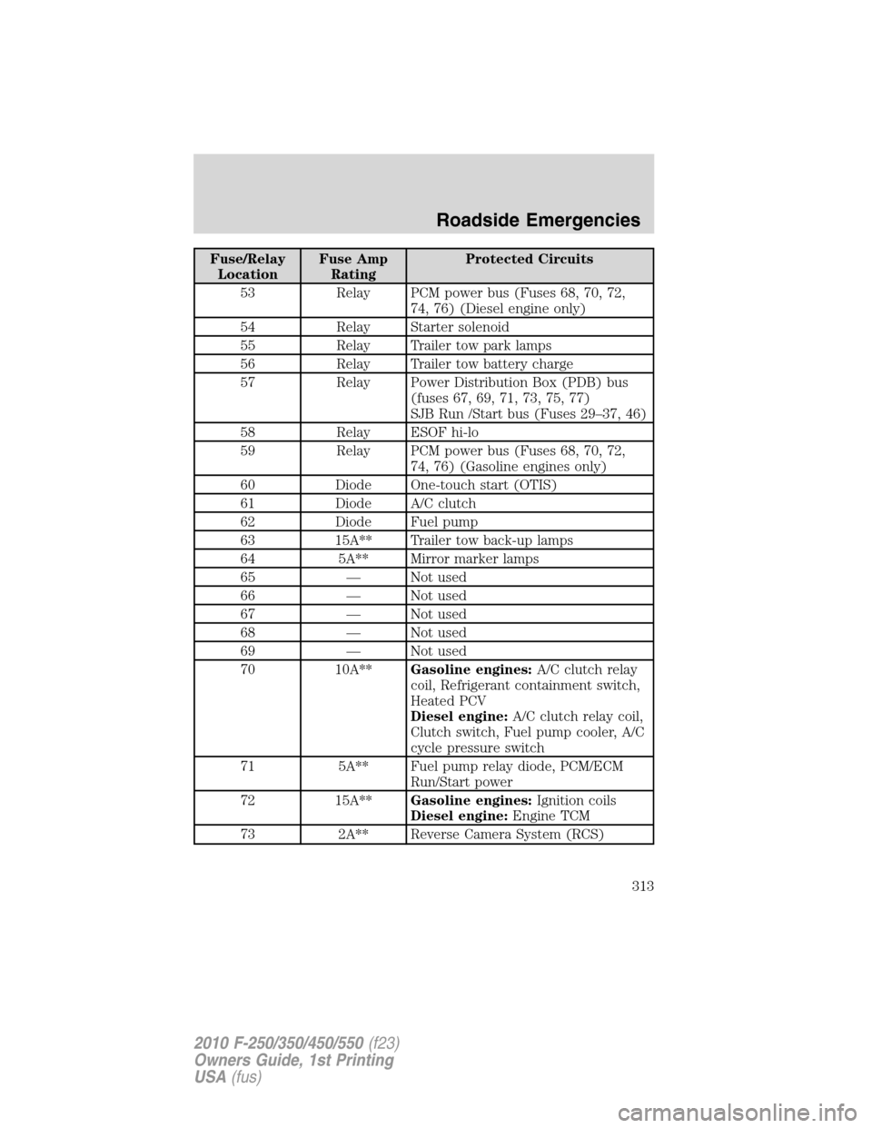
Fuse/Relay
LocationFuse Amp
RatingProtected Circuits
53 Relay PCM power bus (Fuses 68, 70, 72,
74, 76) (Diesel engine only)
54 Relay Starter solenoid
55 Relay Trailer tow park lamps
56 Relay Trailer tow battery charge
57 Relay Power Distribution Box (PDB) bus
(fuses 67, 69, 71, 73, 75, 77)
SJB Run /Start bus (Fuses 29–37, 46)
58 Relay ESOF hi-lo
59 Relay PCM power bus (Fuses 68, 70, 72,
74, 76) (Gasoline engines only)
60 Diode One-touch start (OTIS)
61 Diode A/C clutch
62 Diode Fuel pump
63 15A** Trailer tow back-up lamps
64 5A** Mirror marker lamps
65 — Not used
66 — Not used
67 — Not used
68 — Not used
69 — Not used
70 10A**Gasoline engines:A/C clutch relay
coil, Refrigerant containment switch,
Heated PCV
Diesel engine:A/C clutch relay coil,
Clutch switch, Fuel pump cooler, A/C
cycle pressure switch
71 5A** Fuel pump relay diode, PCM/ECM
Run/Start power
72 15A**Gasoline engines:Ignition coils
Diesel engine:Engine TCM
73 2A** Reverse Camera System (RCS)
Roadside Emergencies
313
2010 F-250/350/450/550(f23)
Owners Guide, 1st Printing
USA(fus)
Page 316 of 407
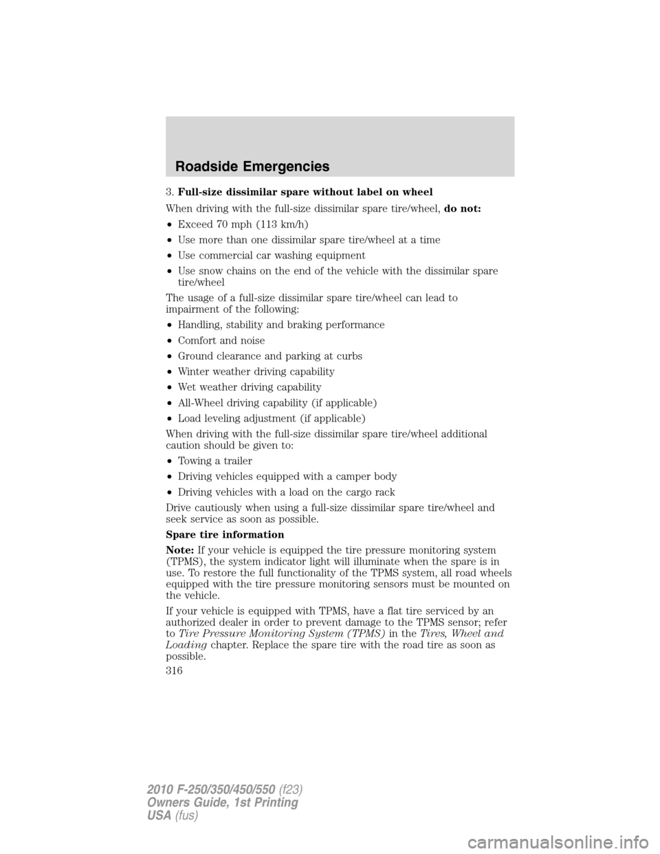
3.Full-size dissimilar spare without label on wheel
When driving with the full-size dissimilar spare tire/wheel,do not:
•Exceed 70 mph (113 km/h)
•Use more than one dissimilar spare tire/wheel at a time
•Use commercial car washing equipment
•Use snow chains on the end of the vehicle with the dissimilar spare
tire/wheel
The usage of a full-size dissimilar spare tire/wheel can lead to
impairment of the following:
•Handling, stability and braking performance
•Comfort and noise
•Ground clearance and parking at curbs
•Winter weather driving capability
•Wet weather driving capability
•All-Wheel driving capability (if applicable)
•Load leveling adjustment (if applicable)
When driving with the full-size dissimilar spare tire/wheel additional
caution should be given to:
•Towing a trailer
•Driving vehicles equipped with a camper body
•Driving vehicles with a load on the cargo rack
Drive cautiously when using a full-size dissimilar spare tire/wheel and
seek service as soon as possible.
Spare tire information
Note:If your vehicle is equipped the tire pressure monitoring system
(TPMS), the system indicator light will illuminate when the spare is in
use. To restore the full functionality of the TPMS system, all road wheels
equipped with the tire pressure monitoring sensors must be mounted on
the vehicle.
If your vehicle is equipped with TPMS, have a flat tire serviced by an
authorized dealer in order to prevent damage to the TPMS sensor; refer
toTire Pressure Monitoring System (TPMS)in theTires, Wheel and
Loadingchapter. Replace the spare tire with the road tire as soon as
possible.
Roadside Emergencies
316
2010 F-250/350/450/550(f23)
Owners Guide, 1st Printing
USA(fus)
Page 320 of 407
WARNING:Do not attempt to change a tire on the side of the
vehicle close to moving traffic. Pull far enough off the road to
avoid the danger of being hit when operating the jack or changing the
wheel.
Note:Passengers should not remain in the vehicle when the vehicle is
being jacked.
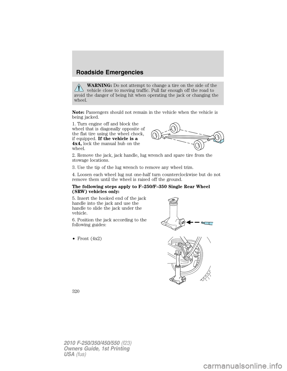
1. Turn engine off and block the
wheel that is diagonally opposite of
the flat tire using the wheel chock,
if equipped.If the vehicle is a
4x4,lock the manual hub on the
wheel.
2. Remove the jack, jack handle, lug wrench and spare tire from the
stowage locations.
3. Use the tip of the lug wrench to remove any wheel trim.
4. Loosen each wheel lug nut one-half turn counterclockwise but do not
remove them until the wheel is raised off the ground.
The following steps apply to F–250/F–350 Single Rear Wheel
(SRW) vehicles only:
5. Insert the hooked end of the jack
handle into the jack and use the
handle to slide the jack under the
vehicle.
6. Position the jack according to the
following guides:
•Front (4x2)
Roadside Emergencies
320
2010 F-250/350/450/550(f23)
Owners Guide, 1st Printing
USA(fus)
Page 325 of 407
15. Remove the lug nuts with the lug wrench.
16. Replace the flat tire with the spare tire, making sure the valve stem
is facing outward on all front an inboard rear wheels. If replacing the
outboard wheel, the valve stem must be facing inward. Reinstall the lug
nuts until the wheel is snug against the hub. Do not fully tighten the lug
nuts until the wheel has been lowered.
17. Lower the wheel by slowly turning the release valve
counterclockwise. Opening the release valve slowly will provide a more
controlled rate of descent.
The following steps apply to all vehicles:
18. Remove the jack and fully
tighten the lug nuts in the order
shown. Refer toWheel lug nut
torque specificationslater in this
chapter for the proper lug nut
torque specification.
8–lug nut torque sequence
Roadside Emergencies
325
2010 F-250/350/450/550(f23)
Owners Guide, 1st Printing
USA(fus)
Page 326 of 407
10–lug nut torque sequence
19. Stow the flat tire. Refer toStowing the flat/spare tireif the vehicle
is equipped with a spare tire carrier.
Note:Do not stow the Harley-Davidson flat tire and wheel using the
spare tire winch mechanism; store the flat in the bed of the truck.
20. Stow the jack, jack handle and lug wrench. Make sure the jack is
securely fastened so it does not rattle when driving.
21. Unblock the wheels.
The following step applies to F–250/F–350 Single Rear Wheel
(SRW) vehicles only:
22. When installing the wheel center
ornaments, ensure that the
ornament retention towers on the
back side of the ornament are
aligned with the studs/lug nuts. The
retention towers are designed to be
installed over the studs/nuts and
retain to the flange on the lug nut.
Roadside Emergencies
326
2010 F-250/350/450/550(f23)
Owners Guide, 1st Printing
USA(fus)
Page 327 of 407
If the ornament retention towers are
aligned between the studs/lug nuts,
the ornament is improperly
installed. This improper installation
may appear and sound correct, but
will not keep the ornament on the
vehicle. Ornaments improperly
installed in this manner will fall off
or become loose with minimal force
or impact.
Installing dual rear wheel ornaments
1. Align the ornament with the lug
nuts.
•(1) is the clip and (2) is the
flange.
2. Hold the ornament so that all of
the retention clips are sitting on the
flange of the lug nuts.
3. Use your hand or rubber mallet to
tap the ornament in a star pattern.
There should be an even gap
between the ornament and the
wheel.
12
Roadside Emergencies
327
2010 F-250/350/450/550(f23)
Owners Guide, 1st Printing
USA(fus)
Page 328 of 407
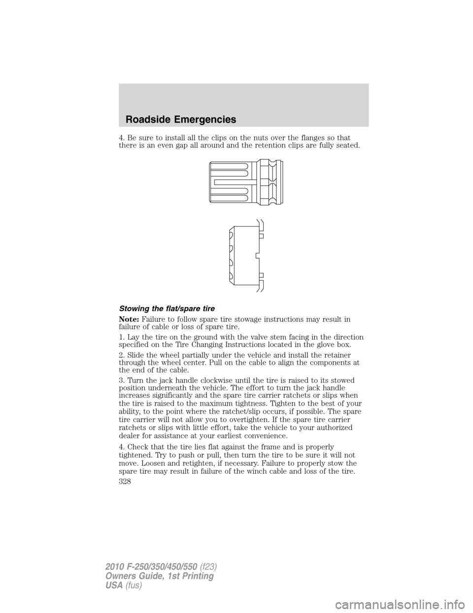
4. Be sure to install all the clips on the nuts over the flanges so that
there is an even gap all around and the retention clips are fully seated.
Stowing the flat/spare tire
Note:Failure to follow spare tire stowage instructions may result in
failure of cable or loss of spare tire.
1. Lay the tire on the ground with the valve stem facing in the direction
specified on the Tire Changing Instructions located in the glove box.
2. Slide the wheel partially under the vehicle and install the retainer
through the wheel center. Pull on the cable to align the components at
the end of the cable.
3. Turn the jack handle clockwise until the tire is raised to its stowed
position underneath the vehicle. The effort to turn the jack handle
increases significantly and the spare tire carrier ratchets or slips when
the tire is raised to the maximum tightness. Tighten to the best of your
ability, to the point where the ratchet/slip occurs, if possible. The spare
tire carrier will not allow you to overtighten. If the spare tire carrier
ratchets or slips with little effort, take the vehicle to your authorized
dealer for assistance at your earliest convenience.
4. Check that the tire lies flat against the frame and is properly
tightened. Try to push or pull, then turn the tire to be sure it will not
move. Loosen and retighten, if necessary. Failure to properly stow the
spare tire may result in failure of the winch cable and loss of the tire.
Roadside Emergencies
328
2010 F-250/350/450/550(f23)
Owners Guide, 1st Printing
USA(fus)
Page 335 of 407
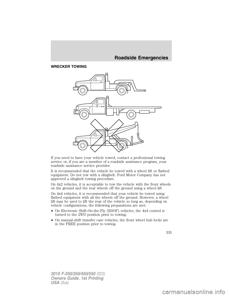
WRECKER TOWING
If you need to have your vehicle towed, contact a professional towing
service or, if you are a member of a roadside assistance program, your
roadside assistance service provider.
It is recommended that the vehicle be towed with a wheel lift or flatbed
equipment. Do not tow with a slingbelt. Ford Motor Company has not
approved a slingbelt towing procedure.
On 4x2 vehicles, it is acceptable to tow the vehicle with the front wheels
on the ground and the rear wheels off the ground using a wheel lift
On 4x4 vehicles, it is recommended that your vehicle be towed using
flatbed equipment with all the wheels off the ground. However, a wheel
lift may be used to lift the rear of the vehicle so long as, depending on
vehicle configurations, the following preparations are met:
•On Electronic Shift-On-the-Fly (ESOF) vehicles, the 4x4 control is
turned to the 2WD position prior to towing.
•On manual-shift transfer case vehicles, the front wheel hub locks are
in the FREE position prior to towing.
Roadside Emergencies
335
2010 F-250/350/450/550(f23)
Owners Guide, 1st Printing
USA(fus)