2010 FORD F750 light
[x] Cancel search: lightPage 186 of 274

Drivingchapter. Diesel fuel containing no more than 5% biodiesel may
be used. Biodiesel fuel is a product that has been converted from
renewable fuel sources, including vegetable oil, animal fat and cooking
oil. Raw or refined vegetable oil, animal fat, cooking oil or recycled
greases should not be used.
Since it is normal for a small amount of unburned fuel to enter the
crankcase and mix with the engine oil, the use of biodiesel requires that
the engine oil and filter be changed more often. Refer to theExceptions
section of theScheduled Maintenance Guidechapter for more
information.
Do not use home heating oil or any diesel fuel not intended for
highway use. Red dye is used to identify fuels intended for
agricultural and non-highway use. Damage to the fuel injection
system, engine and exhaust catalyst can occur if an improper fuel
is used. Do not add gasoline, gasohol or alcohol to diesel fuel.
This practice creates a serious fire hazard and engine
performance problems.
NOTE:Use of any fuel other than those recommended may cause
powertrain damage, a loss of vehicle performance, and repairs may not
be covered under warranty.
WARNING:Using low sulfur (16-500 ppm) or high sulfur
(greater than 500 ppm) diesel fuel in a diesel engine designed to
use only Ultra Low Sulfur Diesel fuel increases the likelihood of engine
oil dilution with fuel which may lead to major engine damage.
WARNING:Using low sulfur (16-500 ppm) or high sulfur
(greater than 500 ppm) diesel fuel in a diesel engine designed to
use only Ultra Low Sulfur Diesel fuel will cause certain emission
components to malfunction which may also cause the Service Engine
Soon (
SERVICE
ENGINE
SOON) light to illuminate indicating an emissions-related
concern.
WARNING:Do not mix diesel fuel with gasoline, gasohol or
alcohol. This could cause an explosion resulting in personal
injury.
Maintenance and Specifications
186
2010 F-650/750(f67)
Supplement(supplement), 1st Printing
USA(fus)
Page 189 of 274

Filling the tank
For consistent results:
•Use the same fill rate setting (low - medium - high) each time during
filling.
•Allow three automatic click-offs when filling.
•Always use fuel of a known quality, preferably a national brand.
•Have the vehicle loading and distribution the same every time.
•When refueling a vehicle equipped with dual fuel tanks, if the two
tanks are not filled equally, the fuel gauge reading may fluctuate
slightly until the fuel level between the two tanks balance out and
become equal.
Your results will be most accurate if your filling method is consistent.
Note:For vehicles equipped with dual fuel tanks, engine performance
may degrade if fuel is not added to both tanks when refueling.
Calculating fuel economy
1. Fill the fuel tank(s) completely and record the initial odometer
reading (in miles or kilometers).
2. Each time you fill the tank(s), record the amount of fuel added (in
gallons or liters).
3. After at least three to five tank fill-ups, fill the fuel tank(s) and record
the current odometer reading.
4. Subtract your initial odometer reading from the current odometer
reading.
5. Follow one of the simple calculations in order to determine fuel
economy:
•Divide total miles traveled by total gallons used.
•Multiply liters used by 100, then divide by total kilometers traveled.
Keep a record for at least one month and record the type of driving (city
or highway). This will provide an accurate estimate of the vehicle’s fuel
economy under current driving conditions. Additionally, keeping records
during summer and winter will show how temperature impacts fuel
economy. In general, lower temperatures give lower fuel economy.
Driving style - good driving and fuel economy habits
Give consideration to the lists that follow and you may be able to change
a number of variables and improve your fuel economy.
Maintenance and Specifications
189
2010 F-650/750(f67)
Supplement(supplement), 1st Printing
USA(fus)
Page 191 of 274

Diesel particulate filter regeneration (Caterpillar engine only)
DPF regeneration requires no operator interaction and may occur at any
time. A small increase in engine sound-level during filter regeneration is
normal and should be no reason for concern.
A separate fuel injector/nozzle, which requires periodic cleaning, is used
in the regeneration process. Refer to Caterpillar’sOperation and
Maintenance Manualfor details regarding cleaning requirements.
Diesel particulate filter regeneration (Cummins engine only)
Under most operating conditions, DPF regeneration will be transparent
to the operator. A small increase in engine/turbo sound-level is normal
during filter regeneration. If, however, your engine is operated for
extended periods of time under one of the following conditions, operator
assistance may be required to facilitate the filter regeneration process:
•Vehicle is operated in stop-and-go traffic and/or maintains low speeds
as in a city/delivery driving
•Engine is started and shut-off frequently
•Vehicle payload is relatively light
•Vehicle is regularly operated in cold ambient temperatures (i.e. below
0°F [-18°C])
Diesel Particulate Filter Four–Level Loading Chart
Level/Lamp status Filter status Requested action
Level 1
DPF lamp solidRegeneration required. Drive on highway at
highway speedsOR
start “parked
regeneration” to
prevent loss of engine
performance. Level 2
DPF lamp flashing
(once per second)Nearly full. Engine
performance is limited.
Level 3
DPF lamp flashing +
Service Engine Soon
lamp solidFull. Engine is
increasingly limited.Perform “parked
regeneration” to
prevent loss of engine
performance.
Level 4
Stop Engine lamp
solidOver full. Engine
performance is highly
limited. Continued
operation may result
in irreparable damage
to the filter.Pull vehicle safely off
roadway, turn on
hazard flashers and
shut down engine as
soon as possible. Seek
service immediately.
Maintenance and Specifications
191
2010 F-650/750(f67)
Supplement(supplement), 1st Printing
USA(fus)
Page 193 of 274

The engine speed may increase slightly. To allow parked regeneration to
continue uninterrupted:
1. The vehicle must remain parked
2. The transmission must remain in P (Park) or N (Neutral) (as
previously described in Step 2).
3. The accelerator pedal, service brake pedal, and clutch pedal (if
equipped) must not be pressed
4. The parking brake must remain set
On average (depending on filter level and other factors), the process will
take 20–30 minutes to complete. The DPF lamp will turn off when the
process is complete. Repeat Steps 1–5, if parked regeneration is interrupted.
To discontinue parked regeneration (Cummins engine only)
Press any of the floor pedals to discontinue parked regeneration.
Diesel particulate filter maintenance and service
The DPF is designed to retain a relatively large amount of residual ash
and provide many miles and hours of maintenance-free operation. At
some point, generally beyond 150,000 miles (240,000 km) or 5,000 hours
of operation (whichever comes first), the DPF will require professional
cleaning to remove the accumulated ash
The exact number of miles or hours of operation will vary greatly
depending upon vehicle/engine loading and operating conditions, ash
content of the engine oil, and quality of the diesel fuel used in your
truck. Adhering to your engine manufacturer’s recommended oil and fuel
specifications will maximize the miles and hours of operation before a
DPF professional cleaning is required. Refer to your engine
manufacturer’s owner’s manual for more details regarding recommended
maintenance and service of your DPF.
Exhaust outlet assembly
WARNING:The normal operating temperature of the exhaust
system is very high. Never work around or attempt to repair any
part of the exhaust system until it has cooled. Failure to follow these
instructions may result in serious personal injury.
The exhaust outlet assembly on your vehicle is a uniquely functioning
device that accompanies the DPF assembly. It is designed to help control
the temperature of the exhaust during the DPF regeneration process.Do
Maintenance and Specifications
193
2010 F-650/750(f67)
Supplement(supplement), 1st Printing
USA(fus)
Page 202 of 274

manufacturer, to ensure that any additional body lights and accessories
are connected to circuits that are both appropriate and not overloaded.
No modification should be made to any vehicle control system without
first contacting your dealer.
SUSPENSION INSPECTION
Note:Do not adjust air suspension height to any setting other than the
specified setting. Altering the height setting will change the driveline
angle and may result in unwarrantable component damage, such as
transmission component damage.
Verify drive axle air suspension height and height control valve
performance at engine lube oil change intervals.
Periodically:
•Check condition of spring leaves for evidence of fatigue, bending or
breakage.
•Check condition of suspension mounting brackets and bushings.
•Check that torque rod mounting fasteners are tight.
•Check to be sure the suspension alignment is maintained at all times.
•Check U-bolts after the chassis has been operating under load for
1,000 miles (1,600 km) or six months, whichever comes first, the
U-Bolt nuts must be re-torqued. The U-Bolt nuts thereafter must be
re-torqued every 36,000 miles (58,000 km). The U-Bolt and nut
threads and seats should be cleaned and lubricated to ensure a “like
new” condition when re-torquing.
Note:See theU-Bolt Nut Torquechart later in this section.
Supporting your vehicle for service
When performing service repairs on your vehicle, first prepare the
vehicle by doing the following:
1. Park the vehicle on a level concrete floor.
2. Set the parking brake and block the wheels to prevent the vehicle
from moving.
3. Select a jack with a rated capacity sufficient to lift and hold up the
vehicle.
4. Raise the vehicle with the jack applied to the axle(s). DO NOT use the
bumper as a lifting point.
5. Support the vehicle with floor stands under the axle(s). If the axle or
the suspension are being serviced, support the vehicle with floor stands
under the frame side-members, preferably between the axles.
Maintenance and Specifications
202
2010 F-650/750(f67)
Supplement(supplement), 1st Printing
USA(fus)
Page 206 of 274

Oil lubricated front wheel bearings
During normal vehicle duty cycle, the lube and air inside the hub/wheel
cavity expands and if not vented, causes pressure build-up that could
cause accelerated seal wear.
There are two venting methods:
•a slit or small hole in the rubber check vent or
•the window
You can use either of these methods to prevent pressure build-up.
Normal maintenance
Over a period of time, if not routinely cleaned, a slight film of oil can
collect dirt around the rubber fill plug and face, which could appear to
be a leak. Routine cleaning ensures that the lube level can be easily
observed through the clear window as intended. In situations where the
window is clean on the outside but discolored on the inside, the lube
level may be checked by inserting a finger through the rubber check
vent hole.
The specified lube level for a clear window type hubcaps is from the
minimum line to + 5/16 inch above the minimum line.
If the lube level should suddenly drop dramatically below the minimum
level, see theWorkshop Manualfor diagnostic procedure.
Installation, tightening and alignment
When installing wheels, be certain that the threads on studs and nuts are
clean to permit correct torque. The mounting surfaces of rims, wheels,
spacer rings and clamps must be free of dirt, rust, lubricants or damage.
Use a wire brush to clean the mounting contact surfaces. Do not use
lubricant on threads.
After the rim or wheel has been properly tightened, it should be checked
for alignment. Rotate the wheel with a piece of chalk attached to a steady,
firm surface, and placed to just barely clear the outside surface of the tire
bead seat. This procedure will point out the high spot. A high spot does
not necessarily mean that the lug nuts have been unevenly tightened. This
condition or misalignment could be caused by a bent wheel.
Use the following installation procedure:
1. Slide inner rear or front tire and wheel in position over studs and push
it back as far as possible. Use care so that the threads on studs are not
damaged.
Maintenance and Specifications
206
2010 F-650/750(f67)
Supplement(supplement), 1st Printing
USA(fus)
Page 208 of 274

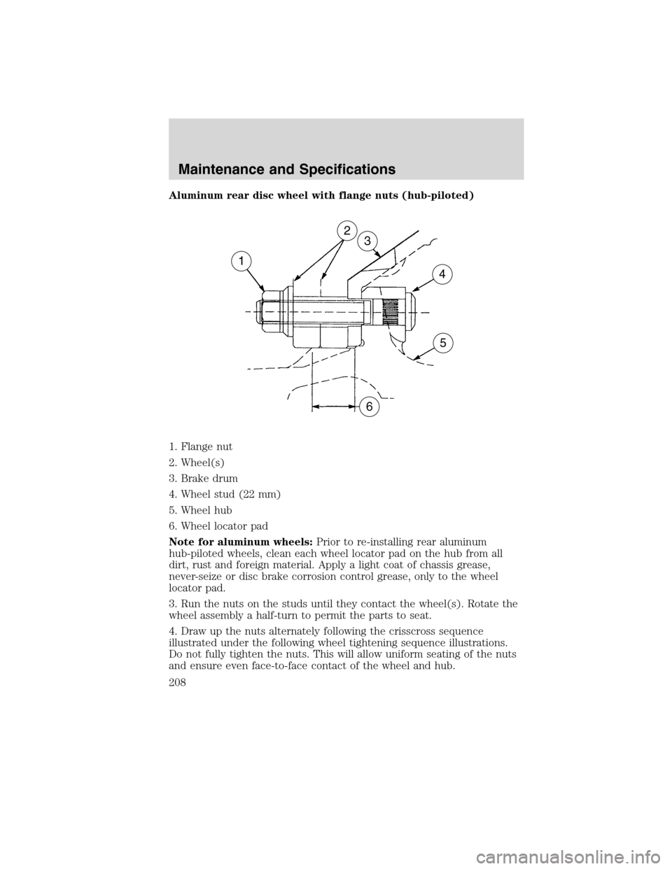
Aluminum rear disc wheel with flange nuts (hub-piloted)
1. Flange nut
2. Wheel(s)
3. Brake drum
4. Wheel stud (22 mm)
5. Wheel hub
6. Wheel locator pad
Note for aluminum wheels:Prior to re-installing rear aluminum
hub-piloted wheels, clean each wheel locator pad on the hub from all
dirt, rust and foreign material. Apply a light coat of chassis grease,
never-seize or disc brake corrosion control grease, only to the wheel
locator pad.
3. Run the nuts on the studs until they contact the wheel(s). Rotate the
wheel assembly a half-turn to permit the parts to seat.
4. Draw up the nuts alternately following the crisscross sequence
illustrated under the following wheel tightening sequence illustrations.
Do not fully tighten the nuts. This will allow uniform seating of the nuts
and ensure even face-to-face contact of the wheel and hub.
1
6
5
4
32
Maintenance and Specifications
208
2010 F-650/750(f67)
Supplement(supplement), 1st Printing
USA(fus)
Page 210 of 274

Changing wheel types
Consult your dealer or wheel/rim distributor before attempting any wheel
or fastener changes.
WARNING:Use only the same type and style wheels and
mounting hardware to replace original parts. Failure to do so
may result in an assembly that looks fine, but does not fit together
properly. This could possibly cause wheel or fastener failures which
could result in property damage, personal injury or death.
Note:Do not attempt to mix stud-piloted wheels or fasteners with
hub-piloted wheels or fasteners.
Note:Do not change from aluminum wheels to steel wheels or
vice-versa without changing the mounting hardware required or, with
flange-nut mounting systems, changing the hub and stud assembly.
WHEEL NUT TORQUE
Size Nut mountingTorque
Ft. lb. N•m
22 mm Flange 450–500 610–678
Note:Do not use lubrication on dry threads. Where excessive corrosion
exists, a light coat of lubricant on the first three threads of the stud bolt
is permitted. Keep lubricant away from:
•Hex nut and rim clamp contact surfaces.
•Cap nut ball face and ball seat on the disc wheel.
•Flange nut washer surface and flat on the disc wheel.
TIRE INFORMATION
Inflation
WARNING:Always maintain your tires in good condition.
Frequently check and maintain correct inflation pressures as
specified by tire manufacturers. Inspect periodically for abnormal wear
patterns and repair/replace cut or broken tire casing. Always use
experienced, trained personnel with proper equipment and correct
procedures to mount or remove tires and wheels. Failure to adhere to
these warnings could result in wheel or tire malfunction, damage to
your vehicle, personal injury, or death.
Maintenance and Specifications
210
2010 F-650/750(f67)
Supplement(supplement), 1st Printing
USA(fus)